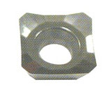
Indexable bits info needed

Home Model Engine Machinist Forum

Help Support Home Model Engine Machinist Forum:

This site may earn a commission from merchant affiliate links, including eBay, Amazon, and others.
hi Kevin, sorry, i have to disagree on that one in the sense that more rake creates smaller shear plane area and therefore requires less cutting force....one of the reasons hss is a better choice imo.
 
Mcgyver said:
hi Kevin, sorry, i have to disagree on that one in the sense that more rake creates smaller shear plane area and therefore requires less cutting force....one of the reasons hss is a better choice imo.

McGyver is absolutely correct. The rake wouldn't matter given a machine of sufficient rigidity, i.e. full scale industrial, but for home machines it matters a lot. Always buy positive rake tooling if you find it. The difference is amazing. Try those inserts too. You'll see.

Even the full on industrial stuff can benefit in a lot of situations from positive rake. One disadvantage is it can make for more wear on the inserts. The latter just doesn't come into play for home shops.

Best,

BW
 
I don't mind the link at all Kevin.

In my own experience positive rake inserts are best for soft metals.
They cut much more freely and eliminate the problem of material building up
on the insert.

On steel, especially 4140 I use inserts with practically no rake.

There is a physical reason for that working better.
Now to see if I'm intelligent enough to explain that. LOL

Cutting metal with carbide inserts involves creating enough heat in a
zone just ahead of the tool to weaken the metal to the point that the pressure
of the tool can separate it from base the material.
The proper term for that area is the "plasticized zone".

A positive rake insert is designed for cutting soft metals. There is very little heat
required for those metals to reach their yield point.
It will not work for tougher alloys. The pressure required to generate enough heat
to cut it would quickly turn the insert INTO a zero rake tool. ;)

And now the next issue will be, "I flood my tools with coolant. How can it develop heat?"
Coolant will keep the part and chips cool. It does not effect the actual cutting zone.
That is happening inside the metal it's self.

HSS works very differently.
It actually comes closer to cutting metal.
It is in fact scraping and tearing the material away, where carbide heats it up and pushes
it off.

My point is, there is no perfect, fits every application answer here.


Rick


Rick, there are a number of articles on positive rake inserts you might find interesting. These are just a few that popped up in Google for me:

http://www.cncmagazine.com/archive01/v1i03/v1i03f-stainlss.htm (Cutting stainless steel with positive rake inserts on the lathe)

http://findarticles.com/p/articles/mi_m3101/is_n5_v63/ai_9000686 (Advantages of high positive rake for milling)

http://www.manufacturingcenter.com/tooling/archives/0201/0201bk_2.asp (Good overview of positive vs negative rake advantages and disadvantages)

http://www.kennametal.com/images/pd...f;jsessionid=FSMX15OUHSKVFLAUBIOSFEVMCQFBYIV0

Machine Shop Trade Secrets also recommends positive rake tooling.

That Kennametal link is particularly interesting. They recommend positive rake for all applications on small to medium sized lathes. Negative geometry only for medium and large lathes. That tells the story for home shop folks right away. The negatives will hog better, but you need to have a machine that can take advantage of it. It is also noteworthy that they recommend positive rake for finishing even on bigger lathes.

What it boils down to is that positive rake requires less cutting force. As I mention before, negative rake inserts last longer in high horsepower deep hogging applications, but for lower horsepower applications and especially lighter weight machines, positive rake generates less cutting force and often a better surface finish. As the 2nd article linked points out, lower horsepower is less than 25 HP, so that's everything we're doing here for sure. The other negative rake advantage is more cutting edges: you can flip a square insert upside down for 4 more edges and that won't work with positive rake. But again, not really a factor for a lot of applications that don't need that economy.

You should check out some high positive rake tooling. It really makes a noticeable difference, particularly on less rigid machines even when cutting something as tough as stainless steel. Those little crown inserts are night and day compared to regular CCMT inserts.

Best,

BW
 
this is a subject where it's easy to have accurate yet seemingly conflicted statements. The reason imo, is that the best rake angle will vary a lot depending on the paradigm; whether you're the lathe or tool bit or material - to resolve you need a sense of how rake effects each.

i respectfully disagree that hss is closer to cutting than carbide, for hss or carbide its a shearing action. along the shear plane, what happens is plastic deformation, however its not unique to carbide. the best analogy i can come up with is its like pushing your finger nail across a bar of soap. As you change the rake you're changing the shear plane angle relative to the surface - as the angle becomes more acute, the area being sheared goes up and so does cutting force. you can take a hss tool with 15 deg or zero and both will cut, but the zero generates a larger shear plane hence higher forces - the lathe wants more rake than less.

the main reason so many carbide cutters are zero or negative rake (even the positive ones aren't that positive) is that a large cutting angle makes for a stronger cutting edge and carbides are weak compared to hss. (they're hard, but brittle) They do not lend themselves as well positive rake. negative rake for example allows a 90 degree tool edge which is a lot stronger than say a 65 degree you might put on hss. hogging off material and getting a long tool life means you want zero or negative rake, but the lathe groans under the increased cutting force.

material hardness affects rake as tougher materials take more force and require a tougher cutting edge. if carbide were magically 10x as strong as hss, the defacto would be positive rake carbide cutters for most materials.

Rick you make a very good point re temp - many use heat and temp interchangeably however no matter how much heat you remove at the surface of the cut, the temp is mostly a result of cutting speed - breaking the speed limit will accelerate tool wear no matter how much coolant you dump on it!

so if that doesn't convince (or bore ) everyone but macona (he's got a monarch) to use hss then we need to discuss the economics in a home shop context :D anyway, longwinded, but that was the essence of why hss tools with their greater positive rake will work better in a light lathe.


This is becoming very interesting.

I've been a "geek" at everything I've ever been involved with.

You know the type.
Show me how it works, then make me understand
WHY it works.


I've been chasing the true understanding of metallurgy as related
to machining since about 1978. In that field of interest 30 years is a
relatively short period of time.

While some may not agree, it IS relative to our hobby.
If we can understand what is happening at the cutting point of a tool it
is easier to select a tool, rake and nose radius to fit the application.

Great information showing up here!

Rick
 
rake60 said:
This is becoming very interesting.

I've been a "geek" at everything I've ever been involved with.

You know the type.
Show me how it works, then make me understand
WHY it works.


I've been chasing the true understanding of metallurgy as related
to machining since about 1978. In that field of interest 30 years is a
relatively short period of time.

While some may not agree, it IS relative to our hobby.
If we can understand what is happening at the cutting point of a tool it
is easier to select a tool, rake and nose radius to fit the application.

Great information showing up here!

Rick

I agree. Materials Science and Metallurgy is very cool stuff. For a long time it was a total black art. There's a lot more science now, but there are still a lot of phenomena that are not completely understood. I am particularly interested in metal finishing treatments and heat treatments. These are somewhat off the beaten track, but fascinating stuff. As I may have mentioned, I hope to make some Damascus steel for a knife at some point.

Cheers!

BW
 
BobWarfield said:
Now here are the "good" inserts:

ccgt.jpg


See how they look like a "little crown"? It's that shape that is the key. They have a lot of positive rake, which is good for small lathes. For a time they were called "CCGT" on eBay, but that's a misnomer. These days I insist on seeing a picture of the insert before I'll buy. The little crowns cut way better and leave a finer finish to boot. It is amazing how much the different insert styles matter on these things.

Bob, that crowned insert looks exactly like the insert that came with a LoveJoy face mill that I have. The geometry of that insert is outstanding. I was shocked at how nice a finish it leaves behind, not only in aluminum but in ferrous metals as well. Here is the LoveJoy at work on a piece of structural aluminum...

p3_07.jpg


I liked it so well, I re-engineered a small lathe tool to accept the insert, and it is now one of my favorite lathe tools. I do agree on the desireability of positive rake tools in general for aluminum and steel. I tend to go zero rake with the copper alloys, though.
 
Swede, I've got a Lovejoy face mill, but its a different one. Still a positive rake design. It cuts well, but I am jealous of the finish I see there!

RE copper alloys, you just can't beat brass except that its so expensive.

Inserts and tooling are one of those things that is regretably not "out in the open." The big co's are used to sending around sales reps who have a wealth of great knowledge, but you have to dig hard to get access. Also, their mindset tends to be focused on commercial realities and not home shop needs (understandably!).

Can you tell us the model # of your Lovejoy face mill?

Cheers,

BW
 
The cutter head is 2" in daimeter, 5 flutes, and has these two printed lines on it...

205F0200ASP2-075R

L-002851-96-00

It is mounted on an R8 shank, also Lovejoy. I bought these as sales samples on eBay, on a whim, because I was very tired of the poor performance of my standard and ubiquitous Bison face mills that use TPG-32X triangular inserts.

The square, positive rake inserts it uses, just like your picture: SPEX-221

As my experience level grows with this particular tool, and milling cutters in general, I find myself really jacking up the speed, far more than the feed, to get a fine finish. My "epiphany" came after watching a 10 HP VMC mount the same 3/8" carbide end mill I have and plunge into a block of aluminum at some ungodly RPM, and the chips came flying off of it like a garden hose, streaming in an arc and landing several feet away. I thought "that cutter is a lot stronger than I thought it was" and ever since then I have been experimenting with very high RPM's and feedrates, with good results.

Anyway, I too am a believer in quality inserts with superior geometry. There is a reason that they are as expensive as they are; they simply work well. Years ago, I took every cheap brazed carbide lathe tool I owned and threw them in the trash, and I machine now with either hand-ground HSS or a better quality indexible tool.
 
Swede, where do you purchase the SPEX-221 inserts? Do they have to come from Lovejoy? Are they expensive?

As for running at ungodly rpm's, that seems to be the trend. Interestingly, you can reach a point where the chips fly off so fast that they carry a lot of the heat away in the chip. That's better for the tooling and the workpiece.

But, it's a real problem for HSM machines. When you look at the range of rpms needed for aluminum versus steel, it's a big gulf. Most of the HSM stuff is set up well for steel's lower rpms, but not so much for aluminum. Eventually I want to build a belt drive head for my mill that uses a 2 speed transmission to go from steel speeds up to at least 8,000 rpm for aluminum.

Best,

BW
 
nterestingly, you can reach a point where the chips fly off so fast that they carry a lot of the heat away in the chip.

not really, the tool and the work and the chip sink heat. the faster you are cutting the more heat goes into the chip but also into the tool and work. Besides, in the context of the tool wear its not heat thats the problem its temperature and that's a function of cutting speed. start running things past theoretical cutting speeds and you're increasing the tool temp at the cut, increase heat = faster wear. better of to run under theoretical speed and feed faster or increase depth of cut

Eventually I want to build a belt drive head for my mill that uses a 2 speed transmission to go from steel speeds up to at least 8,000 rpm for aluminum

too what advantage? the constraint isn't' so much rpm as removal rate. if i wanted to i can stall out my 2500 lb 2 hp excello at 1000 rpm in AL. you're just dulling cutters if you're taking a .005 depth of cut and .0001 chip per tooth. worry more about maximizing removal rates in cubic inches to the machine's constraint (horsepower, rigidity) then worry about rpm. many many machines will be constrained by removal rates long before they will on speed, hence one of the main advantage of carbide is lost and spinning the cutter faster doesn't do much.

otoh if you're spinning engraving cutters or 1/16 end mills, speed is advantageous. Then the issue may be the bearings and spindle - the existing may not last or work well at a big bump in speed. as you go faster you may encounter balance issues....why might have been ok with static balancing at 2000 rpm maybe needs dynamic balancing at 8k; that sort of thing. if you do need a high speed for light jobs like engraving or circuit board milling it might be better to make a separate light duty fast spindle.
 
Hi
There are a lot of misconceptions regarding spindle speed. I see this from time to time at club events. The assumption is the higher the speed the better the finish. Well in some cases this is true but not always. I machine a few parts on a regular basis for a company from 2011 aluminum and the spindle speed never goes past about 600rpm and the finish is good enough to not want any work.
In the past I have also had jobs in EN1a steel that called for 3000 plus RPM with very very lite cuts.

Another point thyats worth remembering is the harder you work the metal the hotter it gets and the more it grows. Dont believe me put a 12 inch long 2 inch diameter bar up in the lathe with a fixed center. Take a few heavy cuts with out coolant measure the bar with a mic. Let the bar cool and measure it again. Also release the tailstoc and reset it whilst the bars hot. Again check it once teh bar has cooled down, itl be loose.
The net effect of heating is to make it harder to hit the size you want. Cutting tools must fit the job your doing as should speed nad feed, but learning what tool does what is trial and error unless your in an apprenticeship. Or you have a good list of books to refer too.

Cheers Kevin
 
Mcgyver said:
not really, the tool and the work and the chip sink heat. the faster you are cutting the more heat goes into the chip but also into the tool and work. Besides, in the context of the tool wear its not heat thats the problem its temperature and that's a function of cutting speed. start running things past theoretical cutting speeds and you're increasing the tool temp at the cut, increase heat = faster wear. better of to run under theoretical speed and feed faster or increase depth of cut

too what advantage? the constraint isn't' so much rpm as removal rate. if i wanted to i can stall out my 2500 lb 2 hp excello at 1000 rpm in AL. you're just dulling cutters if you're taking a .005 depth of cut and .0001 chip per tooth. worry more about maximizing removal rates in cubic inches to the machine's constraint (horsepower, rigidity) then worry about rpm. many many machines will be constrained by removal rates long before they will on speed, hence one of the main advantage of carbide is lost and spinning the cutter faster doesn't do much.

otoh if you're spinning engraving cutters or 1/16 end mills, speed is advantageous. Then the issue may be the bearings and spindle - the existing may not last or work well at a big bump in speed. as you go faster you may encounter balance issues....why might have been ok with static balancing at 2000 rpm maybe needs dynamic balancing at 8k; that sort of thing. if you do need a high speed for light jobs like engraving or circuit board milling it might be better to make a separate light duty fast spindle.

Mcgyver, let me see if I can vector you on to some information to change your mind on these two points.

Let's start off with spindle speed and aluminum versus steel. What's the "correct" speed for a 1/2" end mill in aluminum?

For aluminum, ME Pro gives 3568 rpm with an HSS cutter or 5352 rpm with a solid carbide end mill. Already we're well past my mill's limit of 1600 rpm and we're even past the Bridgeport's 4000 rpm limit. Now what about a 3/8" end mill? I'm getting ready to use one as we speak to make the slot in my disc sander table. The slot will be 1/2" wide, but it'll be nicer if I machine with a smaller mill than if I try to get the slot in one pass. For aluminum, a 3/8" end mill wants 6458 rpm. BTW, you talk about maxing out for the machine's HP. ME Pro has a nifty feature that tells you the required HP for these operations. The 3/8" carbide example wants just 0.179 HP. The 0.5" carbide wants 0.219 HP. So we're nowhere near maxing out the 2HP motor on my mill, let alone a 3 or 4 HP mill. 3/8" is still not that small of an end mill to be playing with here, especially if you're making models. 1/4" carbide wants 7655 rpm. Are you starting to see why I want the belt drive? Look at the mills that came after the Bridgeport. For example, the Tree CNC knee mills. 8K rpm is their design target. That's what you need for best work in aluminum.

Here's another issue to consider: I'm into CNC and 3D profiling. That means ball mills. Guess what? As you profile on the end of the ball, the actual speed varies by how far off the center of the ball you are. The cutter is hardly moving in the middle. So you want more speed on these profiling ops.

Most people are nowhere near the "theoretical" cutting speeds you mention. It's an eye opener to use one of these programs to see what those speeds ought to be. Even more interesting is to run at the recommended parameters versus what you had been doing.

Now as for the issue of whether faster speeds can remove the heat. It's a matter of how long the tool and work have to sink the heat. Faster speeds will generate more heat, but there is very little time for the chip to transfer the heat to either the workpiece (ruining your accuracy as compound driver points out) or the tool. It turns out that if chip formation is working well (another touchy thing to tune up), you can come out ahead going faster. One of the many available articles had this to say about the topic:

Using the appropriate cutting parameters can also help to keep heat generation to a minimum. The most obvious way that higher speeds and feeds can do this is to reduce the chip load while getting through the material faster. Spending less time in the cut reduces the time available for generating heat and for letting it soak into the workpiece.

(http://www.mmsonline.com/articles/100302.html)

For those who don't want a coolant mess, that's a fascinating article on dry cutting, BTW. But there are many of these articles advocating higher spindle speeds. You can read about speed taking the heat out in the chips on places like the PM boards too. The truth is that cutter geomety (lots more talk of positive rake in these same articles) and metallurgies have gotten dramatically better, so the tactics for how to get the most from these cutters have changed.

It's surprising just how fast you ought to be running or how much feed is optimal. That's why software like ME Pro is so helpful. Incidentally, his software is table configurable if you need to "tune" it to your machine's capabilities or your preferences. I find on the conservative to radical scale he is a 7 where 1 is conservative and 10 is radical. The best (too expensive for home use!) cutters can run as a 10. For comparison, my CAM program also recommends feeds and speeds and is slightly more conservative, perhaps a 6. Without software like this you can spend hours puzzling over manufacturer's recommendations.

FWIW, I only run "name brand" cutters. They can be bought cheaply on eBay for not much more than the cheap imports if you shop carefully. These cutters run great with ME Pro's recommendations. Cheaper cutters won't hack it, and it's possible a lighter mill wouldn't either. If you own a mill whose rigidity is in doubt, ME Pro's horsepower calculator may give you a way to play with the parameters to minimize cutting forces so your mill flexes less. Just an idea.

Can we run slower? Absolutely! Folks do it all the time. You can get good results too, but it would be a mistake to assume there's nothing to be gained by running the cutters where they're design to be run. OTOH, it's a hobby. Have fun and be safe. My particular "fun" involves learning as much as I can about some of these finer points. Hence I spend a lot of time experimenting and reading trade articles. The best thing is to experiment for yourself. One of the neatest tool improvement I made was variable speed on the lathe. It's amazing how much you can learn playing with it during actual cutting about things like chatter. One of the admonitions I hear from pros about parting off is "lean on it harder if it chatters." I was terrified to do so on my puny lathe (no Mori Seiki that!), but it turned out to really help. More so leaning on feedrate than spindle rpm, but it was a learning experience.

Cheers!

BW
 
roger Roger whats your vector Victor

with more time in it you won't need the software, speed is 4*CS/dia , doesn't matter whether you're turning drilling milling etc. i do a quick mental check, but after a while it becomes almost automatic. Anyway, my point wasnt' that you shouldn't or can’t cut at the theoretical max speed, only that its very often the removal rate of the machine that is the real constraint and therefore cutting at that speed only accomplishes faster tool wear.

Deciding what speed feed and DOC is a balance around the removal rate constraint - and that’s determined not just by horsepower but by machine rigidity, set up, tooling etc. You can’t get the machine constraint from a program, its experience and learning the particular machine, levels of wear, different qualities of bearings, different rigidities etc etc.
you can get to X removal rate with a high speed, small DOC and slow feed or you can get there with more DOC, more feed and slower speed - the latter is preferred.

consider the example you gave - as I implied, if the cutter gets so small the machine constraint isn't there, speed can be advantageous - 3/8 is small enough that removal rates are less an issue; say than using a 1” cutter. Still, lets work through it. You didn't state depth of cut but lets say .1875. To push things to make the point, a 3/8 carbide endmill could spin at 1100 fpm or about 11,000 rpm. However to get a decent chip load you'd need a 35 ipm feed rate! - is the mill or cutter going to stand that at .1875 DOC? btw at those specs, hp is more like 1 so its not a free for all quite yet and the removal rate constraint isn't just determined just by horsepower , its machine rigidity, tooling, set up etc. There is nothing inherent in cutting AL that makes it better faster…..stay with the machine constraint by lowering speed….when the machine constraint doesn’t apply step it up but keep the surface speed below theoretical to maximize tool life.

Now as for the issue of whether faster speeds can remove the heat. It's a matter of how long the tool and work have to sink the heat. Faster speeds will generate more heat, but there is very little time for the chip to transfer the heat to either the work piece

The article you pointed to is referring to dry machining and using the chips to remove heat. Interesting but irrelevant to tool wear and speed which was the jist of my post – when you increase the speed you increase wear. Wear rates result from the localized temperature just back of the cutting edge – this is the area exposed to abrasive friction and the hotter it is, the more rapid it wears. the heat is created by the friction of the chip. To understand wear its needs to be appreciated how this works….the heat in the tool is generated by friction with the chip not by transfer. Heat in the work and chip by plastic deformation are not the source of heat in the tool. Heat build up in the tool needs to be considered but that’s a function of coolant and tool itself – how fast or slow the chip comes off can’t remove this heat. The only effect speed has, so far as the tool is concern, is to create more or less friction. Now, you can have a flood coolant leading to almost no heat build up, however it would not change what I said; that tool wear goes up with speed. This flood would arrest heat buildup but the temp in the first few layers of molecules on the rake face experiencing abrasive friction determined by speed and will be at the same temperature regardless

Using the appropriate cutting parameters can also help to keep heat generation to a minimum. The most obvious way that higher speeds and feeds can do this is to reduce the chip load while getting through the material faster. Spending less time in the cut reduces the time available for generating heat and for letting it soak into the work piece

This just isn’t so in context of tool wear. (Since I’m being vectored I’ll assume the context is as my original comment; tool wear as a function of speed.) If you decrease the chip load and swipe the cutter through it more times you increase tool wear. If you run a tool faster your increase tool wear. You’ve made factural statements about heat, but you can do so until the cows come home and it doesn’t change the fact that the determinant for tool wear is temperature, not heat, and temperature is determined by cutting speed.

all in the spirit of making chips and learning. :D


Okay... and just how many angels have we now determined can dance on the head of a pin? Sounds once again like old fashioned cat skinning and the fact that you can correctly do it more than one way.

I like the insert Face Mill idea and have been watching for a good buy. My intent is to use it much like a flycutter, working with light cuts to get a fine flat surface finish. In this context, would a small belt driven asian mill/drill be capable of safely swinging a 3, 4 or 5 inch face mill?

Steve
 
Okay... and just how many angels have we now determined can dance on the head of a pin?

Steve, can you explain what you mean by that....i feel like its a bit of shot when I'm trying to explain what is going on when cutting metal...there's not much subjective about it, we're not talking different ways of skinning cats, nor is it so esoteric that it doesn't belong - maybe it's boring but it's the foundation to understanding feed, speed, wear etc. Anyway, Bob's smart and we've conversed on many boards, I don't thinks he's going to be put off by a good discussion or someone disagreeing.
 
Cedge said:
Okay... and just how many angels have we now determined can dance on the head of a pin? Sounds once again like old fashioned cat skinning and the fact that you can correctly do it more than one way.

Aha! A wise man has cut to the heart of the issue. You can indeed do it more than one way, that's my point and Steve's not taking a shot at you at all, Mcgyver. I'm not sure why this discussion has set you on edge, but rest assured, I do see your point and I'm also not taking any shots. Nor am I taking any offense, but you should relax a bit.

You can match lower rpms and slower feedrates and still get the correct chiploads or you can run higher rpms and faster feedrates. We simply differ on which makes sense to do. Lest ye think it's impossible to run the faster scenario I propose on my mill, here is a movie of a Tormach (very similar to my IH Mill) running the scenario under discussion of a 3/8" endmill, 3500-4500 rpm, and 30 IPM feedrate:

[link]https://www.tormach.com/MfgDatabase/MFG_20108_LR.wmv[/link]

I think that's pretty cool, and it sure shows the operation is within the machine constraints I'm dealing with. My IH mill is very similar to the Tormach.

But here is the real gist of why there are two ways, and why Mcgyver and I differ (I think):

The equations (of which Mcgyver thoughtfully provided one example) allow tradeoffs. For the cutter and material, we want a particular SFM. We also want a particular chipload. How big a chip is the cutter trying to peel off at a time? These operations have tradeoffs involving the rate at which we can remove material, the machine and tool's rigidity to resist cutting force without flexing or chattering, the spindle's horsepower (which is most of the cutting force) so it doesn't bog down, and the cutter life. We can balance the equations in various ways.

Mcgyver (I believe) advocates balancing the equations to lower spindle speeds. He'll slow down feedrate to keep the chipload right for a decent finish, and he doesn't see why this isn't the best way to go. For a given set of tradeoffs, it probably is, but they're not necessarily my preferred tradeoffs. Mcgyver's method will emphasize:

- Stressing the machine less (potentially, but we'll see more on this shortly)
- Not having to mess with increasing the spindle's speed limitations (granted, this is hard, but its a hobby and I'm interested in building a spindle)
- Maximizing the tool life. He's really derating those tools running them well under the recommended numbers. That's cool, but small endmills just don't cost that much for me to care.
- Maybe not having to crank the feed so fast you'd go crazy (but remember, I'm running CNC as I said from the beginning).

At the lower rpm's, Mcgyver's primary mechanism to cut as fast will be more depth of cut. Personally, cranking depth of cut has been more of a machine capability issue than running the spindle too fast. We can also just live with slow metal removal rates by keeping DOC low.

That's all fine and well, but my goals are different. As I mention, I'm into CNC. This gives me a few more options. For example, I can rebalance the equations around high spindle speed, high feedrates (same chipload as Mcgyver), less depth of cut (which is how I lower cutting force enough not to stress the machine) and more passes (no problem, its CNC). My belief, and I think the Tormach video shows an example clearly, is that I can make parts faster that way. You may not care how fast the parts are being made, particularly if you're turning handwheels. My certainty is that what I'm proposing is completely within the parameters of how these things work and of what Mcgyver is saying. There is not just one way to skin the cat, and it is subjective in the sense that you have to choose your tradeoffs.

Ironically, the trade off I propose--going faster spindle less DOC--is precisely what the trend has been on modern CNC tools. They're lighter and less rigid than mills of old. But their spindles run way faster. They figured out that you can deal with a less rigid machine by lowering the DOC and making more passes with a faster spindle and high feedrates. It's a sound principle and well documented. It's ultimate conclusion (so far) is the High Speed Machining trend, but it works at much lower rpms too. To my way of thinking, that's applicable to "home scale" tools, which are lighter still, if only we can get spindle speeds up.

So yes, there really are more ways to skin the cats.

Cedge, I wouldn't get too carried away on the face mill. I've got a 3 inch. Turns out its similar to Swede's, just a little larger. Unfortuantely, mine is 225 and Swede's is a 205 series. His has even more positive rake and is even better suited to smaller machines. Check out Lovejoy on eBay. They sell samples as Sweede suggested. I'd go for a 2 or 3 inch. They're awesome for surfacing. Make a light cut with a flycutter as your final pass if you want a nicer finish and you're done.

Best,

BW

PS I won't even get started on the chips removing heat issue, but that's also well documented in the trade pubs if you want to go read up. I do think dry machining is relevant since most home shop folks run pretty dry. Hence I like to research that topic. Rather than further burden this discussion, I may do a writeup on this one with references on my cnccookbook web site.
 
Bob, I'm very relaxed.

Mcgyver (I believe) advocates balancing the equations to lower spindle speeds. He'll slow down feedrate to keep the chipload right for a decent finish, and he doesn't see why this isn't the best way to go.

Sort of. depends on the job. you have to factor in how much is being removed. the context of my remarks was maximizing tool wear to removal rate. i don't have a problem cranking the speed & feed up when there's .010 to come off...but when there's .500 to come off, if you take 50 passes, you won't maximize tool life with such a small DOC - you'll just be will wearing out the end of the tool. Also, as i said, this approach is less applicable when there isn't a removal rate constraint. I'm not saying there is a a right/wrong way to do it...I don't have a method, I machine to the situation at hand and was trying explain what goes on so that others would know how to judge each situation and decide on what needs to be done.

i said up front that there are instances when speed is advantageous, but to stay within the envelope of removal rates before you worry about speed is a sensible strategy. its not federal law, you can run any speed you like, as you say you'll just buy more endmills....but in understanding the theory of tool wear and to understand how its life and removal rates are affected by speed feed doc etc, the cost of the endmill shouldn't matter. I'm not telling you what speed you should run at, only what happens and what the challenges are.

if I'm testy about it its because I have been trying to explain in this thread the mechanics of what is going between work and tool, where and how heat is created, how speed comes into it, how it effects tool wear, etc etc etc. It is not subjective, nothing you or i are going to do is going to change the dynamics of how the chip forms, how the abrasive friction heats the tool or how the elevated temp on rake face determines wear. what you do with that knowledge is of course completely up to the individual, but that doesn't change what's going with respect to speed, wear, temperature etc.

re the multiple references to heat, you keep offering this like you're going to set me straight, which is fine, I'm always prepared to be wrong and learn, but I've never said there isn't heat dissipation from chips.....what I've been trying to explain is that it doesn't have much to do with tool wear. read again how heat is created on the tool and how regardless of dissipation its the localized temp on the rake surface that determines tool wear and that temp is determined by speed and that temp determines tool wear.

your statement about a lighter DOC and more passes = less rigidity is interesting. From what I've read there is proportionality between removal rate and force. forgetting for a moment any shock load (like running a cutter a 50 rpm) a removal rate of X cubic inches per minute will generate a force of Y against the clamping set up - regardless of how its removed. interesting point though, I'll have to learn more about it.


Latest posts

Back
Top