I.C. Piston Rings

Home Model Engine Machinist Forum

Help Support Home Model Engine Machinist Forum:

This site may earn a commission from merchant affiliate links, including eBay, Amazon, and others.
Pat I make my rings in adifferent way to what you are describing.

They are turned to finish size eg 1" bore cyl then the OD of the ring is machined to 1". They are then split open, spread over a piece of metal to give the required uncompressed opening and then heated. This results in them retaining that uncompressed gap so that they have the tension when inserted into the cly and are then gapped with a feeler gauge.

You seem to be making oversize rings which are then compressed without any heat treatment.

Jason
 
Hi Brian.

Brian Rupnow said:
I didn't think you could do that on an i.c. engine!!!

Most model air plane engines are ring-less, mainly due to the way they are ported. WarEagles' Crusader .60 is a good example. Rings are also an easily replaceable wear item, and allow for greater piston/cylinder tolerances.

Cheers

Jeff
 
Hello Brian,
Very timely post. I am currently making an Upshur engine, and last night I made the two cast iron rings for the aluminum piston. The cylinder is .750 DOM steel tubing. I have made several of these engines, and used various methods for rings including Viton. I used to go through all the calculations for expanding the rings and calculating clearances, but a few years ago I settled on something simpler. I finish the cylinder including honing to a mirror finish first. Then I turn the OD of a piece of grey cast iron to the exact ID of the cylinder bore. I lap this with oiled 400 wet/ dry paper to get a smooth finish, and this removes a few thousands to give me a smooth slip fit in the bore. I bore the ID of the cast iron to give me about .o32 thickness, and part off several rings about .045 wide. I lap these on the oiled 400 WD paper to deburr. I then recheck the fit by sliding them into the bore, and looking at a light to see if I see any light around the edges. Hopefully none in visible. I clamp the ring in a small mill vise, and use a small pair of pliers to very gently twist the ring next to the vise which cleanly breaks it. I re-chuck the ring, and with a folded piece of the 400WD paper I clean up the break and open it up about .002. I then make the piston .005 undersize of the bore, and use a HHS tool bit which I have ground into a stubby .047 wide parting tool to turn the two ring grooves to a depth of .035. I do not heat treat the rings or spread them to produce any gap. I deburr the piston, and use three small pieces of .005 brass shim stock to assist sliding the rings over the piston, and into their grooves. The rear of the cylinder has a slight champher so I apply some light oil to the piston, and install it for a test fit. If the fit is OK that is having a smooth slip fit and no binding then I go on to other parts of the engine. If there is a problem then I fix it. but so far all is well. after the engine is finished and running the rings seat themselves, and increase the compression. All of the other methods have merit, but this is how I do it, and it has worked well . Good luck. Art
 
Has anyone made Dykes ( L shaped ) rings? Are they any more difficult to make?

Greg
 
I aslo saw some model engines that have about 5 small holes on the piston head leading to the piston ring. Does anybody ever dont it or have an idea if it works on these moedl engies or it will ruin the compression. I was thinking of drilling 3 or 5 holes with a diameter of 0.8mm.

Thanks
Drei
 
These holes are for oil control Drei, excess oil is scraped from the bore by the scraper and oil-control ring, and returns to the sump via these holes. Well it does on full-size engines! :)
Stew
 
Jason, that is the method I have seen described for model locos too. Makes more sense to me as the radius will match that of the bore.

Nick
 
Alright!!!--A decision has been made. I am determined to have this engine as friction free as possible. I am going to buy a length of grey cast iron to make a new cylinder liner and a ringless piston. If I have to tear the engine down anyways, its actually less work to make a new cylinder liner and piston than it is to make rings. This doesn't mean I will never make rings----just not on this engine. Anybody on this forum who has experience building one of Bob Shores ringless engines please chime in and tell me as much as I need to know re piston design and fit--PLEASE-PLEASE.---Brian :-* :-*
The following is an exerpt from Bob shores tips on building i.c. engines

"If you are building a slow running (less that 1000 RPM) and a cool running (less than 170 degrees F) engine, a cast iron cylinder and piston is the best choice due to it's coefficient of expansion and natural (carbon) lubricating characteristics. With this setup and a little WD-40 in the fuel to suspend carbon particles, rings are not required for good compression during the first 1000 hours of running time."


Drei said:
I aslo saw some model engines that have about 5 small holes on the piston head leading to the piston ring. Does anybody ever dont it or have an idea if it works on these moedl engies or it will ruin the compression. I was thinking of drilling 3 or 5 holes with a diameter of 0.8mm.

Those are called gas ports. They are drilled in the top of the piston to the back of ring groove. They are effective, but only needed in very high performance applications. OS uses them in some heli two stroke engines. http://www3.towerhobbies.com/cgi-bin/wti0001p?&I=LXVHG9&P=Z

For cams, the hardest part is the design of a good cam. Making it, once you have the profile, is a math exercise best done with a spreadsheet. Intricate cam design is somewhat a secretive thing. There are no free programs for complex engine cam design, plenty of money is to be made by those that know what they're doing. Basic cam design software is readily available including this http://modelenginenews.org/design/index.html

Greg
 
Thanks Greg for the info, and yes thats where i saw the piston head holes which i think im going to drill some in my next engine.
As for the cam design, i used and tried the cam programm that you ave me on modelenginenews site. To have a high rpm engine does the accelertaion make any difference. I mean that the accleration is calculated by the programm so what does it mean if it come a high value or low what difference does it make more rpm or just high rate of accleration????

Thanks
Drei
 
Brian, with regards to fit I would say the same as what is done on a flame gulper. As close as you can get but with the lowest friction you can get. If one end of the liner is sealed up, you should be able to push on the piston and it spring back then if that seal is taken away, the piston should fall through the liner under its own weight.

Many people lap the bore and liner but I couldn't keep it parallel and round doing that so I bored it then used an adjustable reamer with plenty of oil just gradually increasing the size to give a good, round, parallel finish. Then for the piston I just turned down to a good fit - again, I tried to avoid polishing with emery and the like as i wanted to keep the piston as straight and round as possible, my lathe gave pretty much a good enough finish, if anything (can't remember) I only gave it a couple of seconds with some emery on a flat piece of metal. This was good enough for mine and flame gulpers are very susceptible to excess friction and leakage.

Nick
 
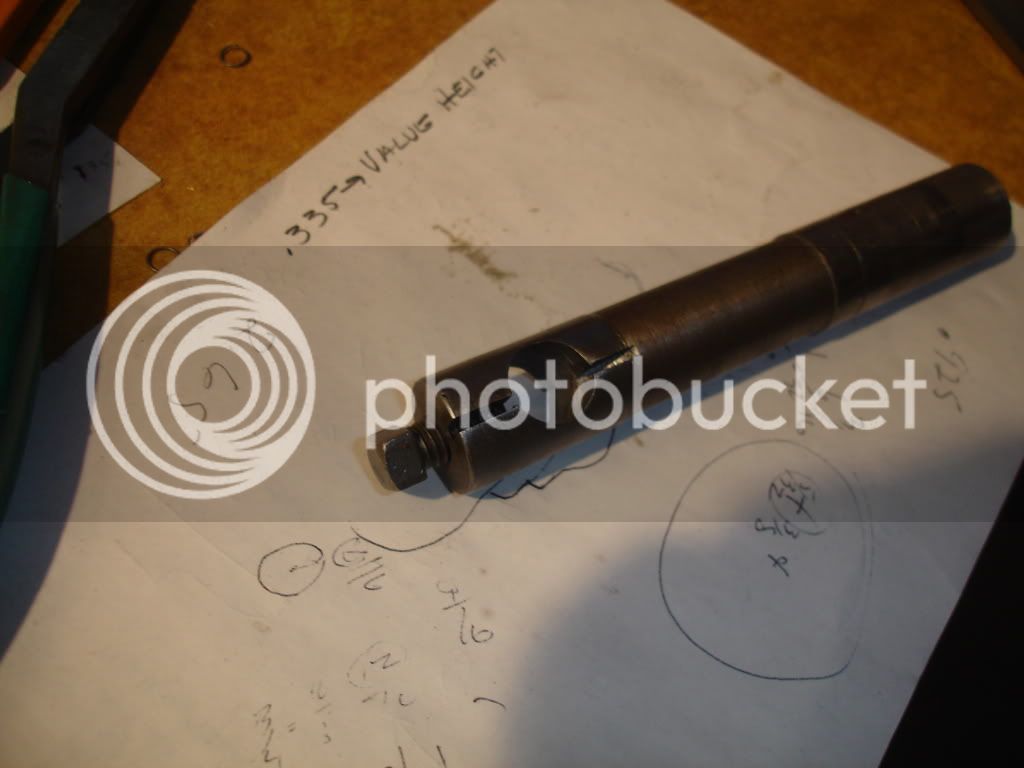
I suggest you lap your cylinders with 120 or there abouts clover compound using a home made lap. Every pass adds only about .0001 to the diameter. Then you add more goop and do it again. After lapping test the cylinder using the tool in the picture. If its not yet straight add more compound and lap it some more. The tool is designed like a small hole gage only bigger. Its diameter needs to be quite close, within a few thou, to the diameter at which you want your cylinder to end up. The screw in the end will expand the gage slightly with a small amount of turn. You'll be amazed with what you can learn sliding this gage in and out. Also, after you're satisfied your cylinder is straight you can mic the gage to determine the diameter for making the piston. I never found the standard telescoping gage to be of much value on a cylinder requiring this level of accuracy. When you lap it so you can't feel any highs or lows in the tube you'll have stepped your skills up another lever and be jumping for joy. Or take it to a shop and get it Sunnen honed. They'll have a bore gage that'll tell you how accurate it is. To work well it needs to be better than within a half a thou. Thats my two cents.
DSC02133.jpg


Sounds a good method but I honestly think people go over the top with lapping. In some cases you don't need to do anything, it can be left straight from the lathe, as long as it's not a blind bore and a few passes are taken with no cut to account for the spring in the boring bar it should be straight, round and parallel. The diameter of the cylinder rarely matters as in the majority of cases you make the piston to suit.
 
I also learned which i think you know it already :), that the piston doesnt have to be a smooth finish. When i machien a piston i sharpen the tool with a sharp point and increase the automatic feed a bit. This leaves like small groves in the cylinder which reduces surface area thus less friction and heat and also helps for oil to stick in the groove.

Drei
 
Back
Top