How to drill off-center holes using mini lathe

Home Model Engine Machinist Forum

Help Support Home Model Engine Machinist Forum:

This site may earn a commission from merchant affiliate links, including eBay, Amazon, and others.
A little closer pic
100_0966.jpg

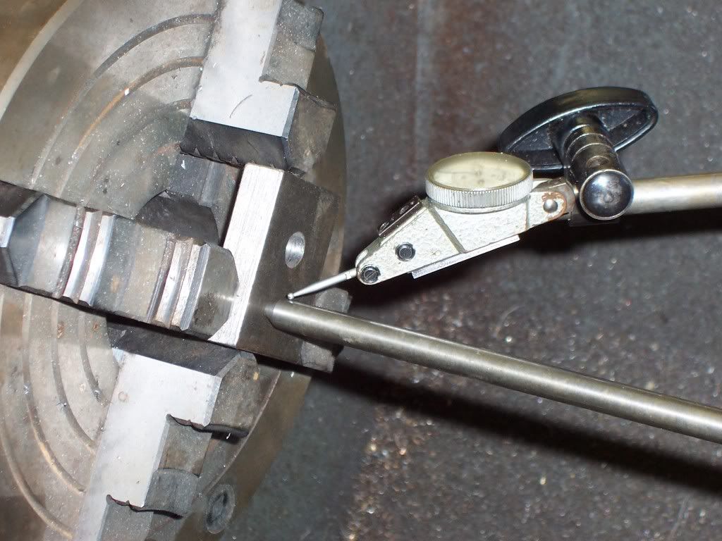
After indicating the part true radially I will go back and reindicate the face to make sure it is still running true. If an adjustment is made to the face the indicator rod is used once again to verify if the center is still running true. It may take a couple of times back and forth between the face and the indicator rod but I can get very good accuracy using this method.
I like to bore holes with this setup if I have to have the bottom of a blind hole square or flat bottomed. It's much easier to do this with a boring bar in the lathe than boring on the mill. If you don't have a boring head for the mill, this is a also good alternative. The accuracy of the location of the hole will be as good as your edgefinder and indicator skills. I hope this helps, Dave
 
Thanks a ton Dave G for taking time and explaining me with pictures :bow: I am reading it again and again to absorb the method :)

ShopShoe: Luckily when I bought my lathe, it came with a 4" 3-jaw chuck. I unnecessarily bought an adapter plate with my 4-jaw chuck and later realized that the 4-jaw chuck mounts directly to the spindle with out requiring an adapter place. As you mentioned, I will double check the chuck for being concentric with the lathe spindle.
 
as long as the 4 jaw ind. chuck is mounted so the face ( the bit that faces the tail stock ) is true ,any slight eccentricity will not matter a jot , its you that set the parts held in it true not the chuck.

with a 3 jaw then yes it has to true in both planes ,the same with a self centring 4 jaw

note turn by hand before power to check for fouling , and check for a out of balance situation ( may need packing the help out )


Stuart
 
Dave G, Looks like you went to all that trouble to explain it to Coolgoose - that's the spirit of HMEM - applause.

Excellent tutorial.

You can of course use the same method clamping the part to a faceplate - adjustment by the judicous application of a hammer.

Ken
 
Thanks a ton everyone for taking time and explaining it to me. I have copied this thread to a word file and kept it in my tutorials folder :)

I have finally managed to drill the two holes for cylinder and valve. I have used trail and error attempts to get the punch mark centered by my dead center for time being. Now, my next immediate task is to make an 60 deg indicator rod and a dial test indicator and wiggler too. It is a very good learning experience for me. I will keep practicing this until I become good at it. So I can take on more complex projects going forward. There is a lot of learning for me to do and I am enjoy every bit of it thanks to you guys here in the forum :bow:

Sorry for poor quality pictures but here is the end result. I have over drilled the hole for valve accidentally, So I made it a through hole. I did not have any reamers, so enlarged the diameters than what the planned called for and then bored them. Boring a blind hole was a quite a bit of experience for me :D Please don't mind the facing I did on the job in the pictures. It is smooth but still there are some gramophone grooves on it. I am still not consistent in getting a smooth finish.


Photo_1EE672D6-5AE2-F440-CC44-B847B7072BBB.jpg
 
Back
Top