Lakc
Well-Known Member
I fired him off an e-mail looking for some dimensions, so I can finalize the drawings and get back to cutting while waiting for them to arrive. Thanks again Steve! :bow:


")


 Everything was done with the X-Y manual handwheels, but I laid the parts out conventionally for a double check.


Yes I am, but trying to keep my eye on the prize here, it has to make noise.stevehuckss396 said:It's starting to look like something now. You must be getting a bit stoked.


 The goal here is to make noise, so even if it does self destruct I will consider it a success.


 A fair amount of drag with piston rings installed but felt good enough to motor on the lathe for some break in, and break in it did, quite a bit of very fine metal particles came out of the oil return port, mostly ferrous in nature. Even without head gaskets, the intake ports sucked and the exhaust ports blew, leading to a very happy home model engine machinist, if I can call myself that yet. ;D

Lakc said:leading to a very happy home model engine machinist, if I can call myself that yet. ;D

 :bow:
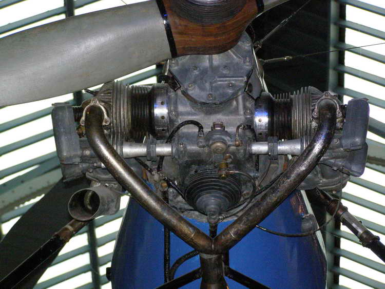
:bow:Lakc said:I did get the prop drive done, as well as the intake tube adaptors.
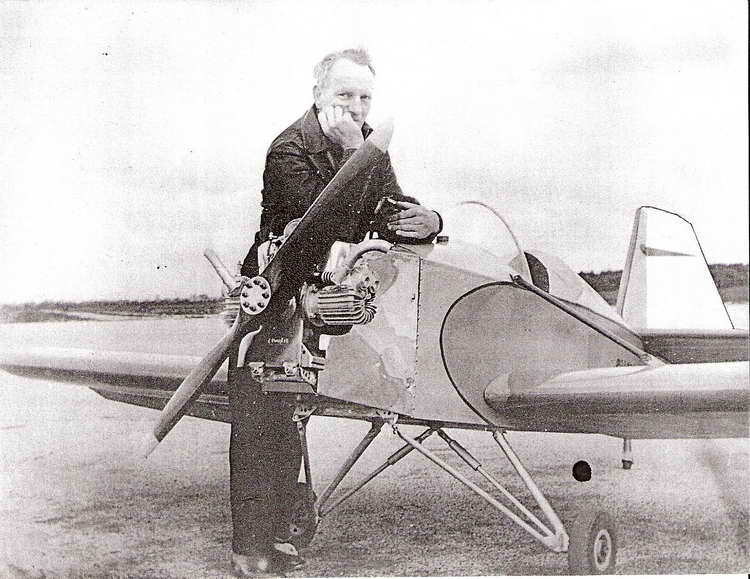
Not necessarily, but its the easiest way to start out imho. No need for a complicated starter system, and the formulas for determining horsepower via rpm and propeller combinations have already been worked out. Keeping a weight budget in the back of your mind sorta forces you think things through a bit more as well. I have been doing R/C stuff for many years, the usages for any small powerplant are only limited by your imagination.stevehuckss396 said:I had no idea that it was going to be an aero engine!!
Very nice job on the prop drive. Love the long nosed prop nut!
Enter your email address to join: