Holt camshaft build tutorial

Home Model Engine Machinist Forum

Help Support Home Model Engine Machinist Forum:

This site may earn a commission from merchant affiliate links, including eBay, Amazon, and others.

gbritnell

Project of the Month Winner!!!
Project of the Month Winner
Joined
Jul 16, 2007
Messages
2,985
Reaction score
1,052
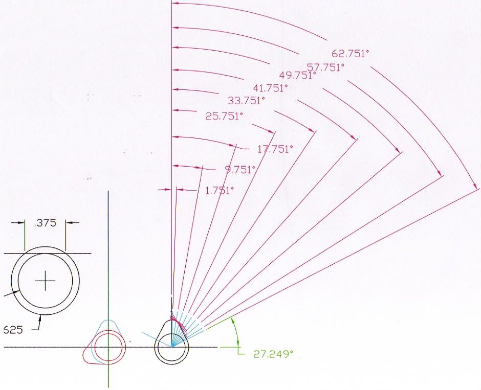
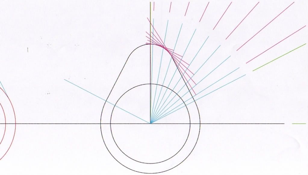
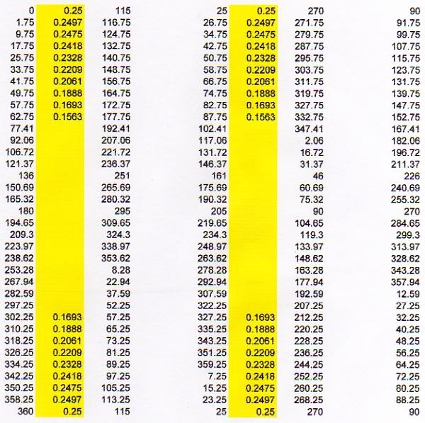
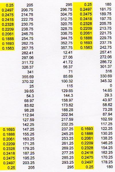
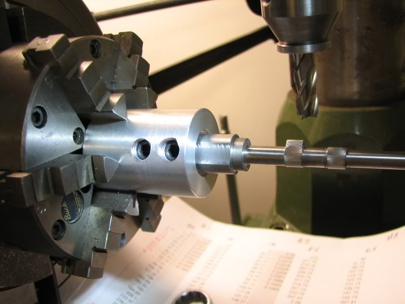
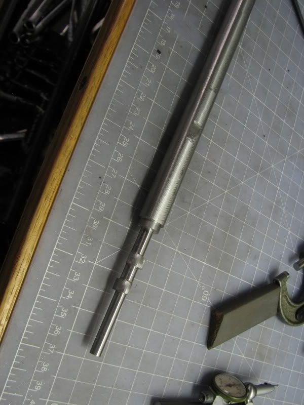
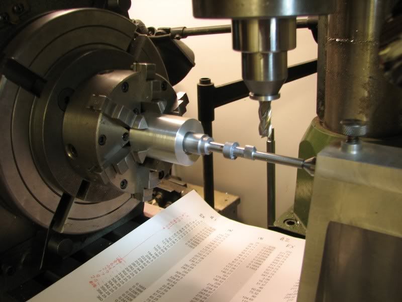
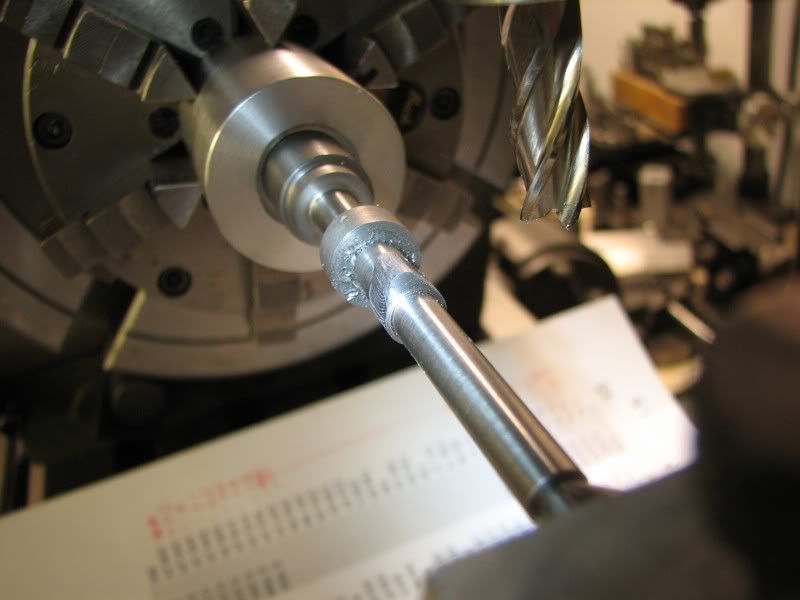
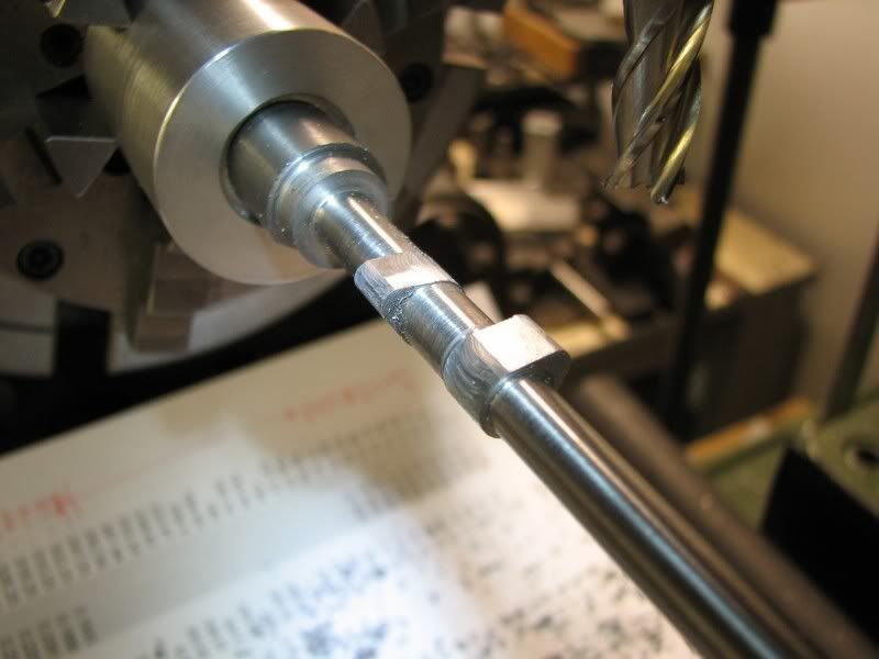
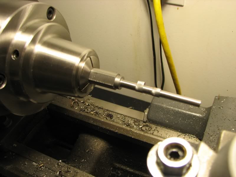
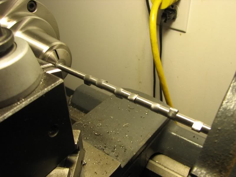
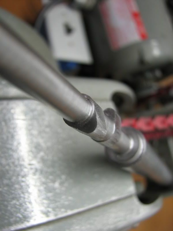
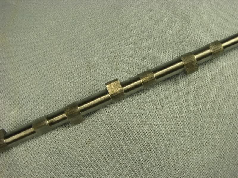
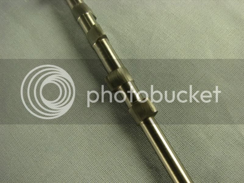
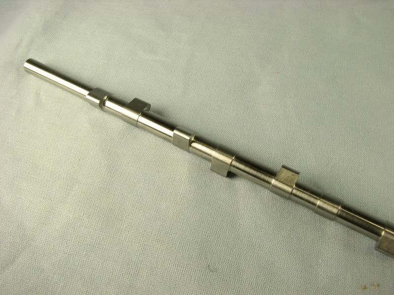
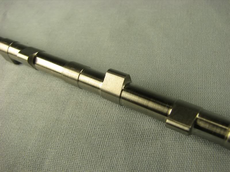
This time we'll do the camshaft. Although this is for the Holt the machining techniques I use can be applied to any camshaft. Eveyone who has made a camshaft has their construction preferences. The earliest way that I read about was the separate lob and shaft type. The shaft is just a piece of steel of choice. The lobes are made from a hardenable steel, O-1, W-1. This piece of stock is drilled and reamed for whatever shaft diameter you are using. The profile is then machined onto it long enough to get the required number of lobes plus cutoff widths. The lobes are then located onto the shaft both lengthwise and radially relative to the timing of that particular valve. This involves some type of fixture to hold the shaft, a degree wheel for indexing and a dial indicator to find the peak lift of the lobe. After locating the lobes are cross drilled through the lobe and shaft for a pin. The lobe is then removed, hardened, replaced, pinned and then the pin is dressed off. It sounds somewhat complicated but at the time home hobbyists were building these they were mainly made for singles and twins. The next way to make a cam is to build a cam grinding fixture. Over the years several variations have been presented in different publications but their function was the same, make a master lobe of the shape required and through a rocking follower grind that shape onto your shaft. The shaft still requires accurate indexing to get the timing of each lobe correct. This is a nice way to go if you first want to build the fixture and second you are planning on making quite a few cams in your career. The next version is the one presented by Steve Huck and others. This involves a lathe fixture with a degree wheel. The shaft is mounted in a fixture on the lathe. It is set off center so that it is turned eccentrically and by rotating the shaft relative to a pre calculated set of degrees the lobe is formed. This procedure will only produce a 'soft' cam. The only way to get a hardened camshaft is to rough out the cam, harden it and grind the profiles or as in the first presentation. I have found for most engines that I have built by just making the cam out of drill rod and leaving it unhardened works fine. I do harden my lifters/tappets so that the wear between the two is kept to a minimum. Now I'll present my way. I'm sure there are others that do it this way but I'll call it my way. I start out with a layout of the lobe shape. In the case of the Holt camshaft the pofile layout is somewhat lacking in information so I took what I thought the author wanted and developed my own profile. I lay out radial lines with tangencies to the pofile that give me 'cusps' of about .0007. You can make them smaller but that involves more steps and more chances of making a mistake. I have found that .0007 is easy to file smooth. When I get these radians layed out I measure how far it is from the center of the shaft out to the flat. I do this for each radian and make a chart of these readings. One number is the angle in degrees the other is the step height.
CAMLAYOUT203.jpg

CAMLAYOUT204-1.jpg

CAMLAYOUT205.jpg

CAMLAYOUT206.jpg


The next step is to take a piece of drill rod whose diameter is large enough to get 2x the lift radius plus enough extra to cut a flat for locating it into my fixture bushing. The fixture bushing in this case is a piece of aluminum bored to the diameter of my stock plus two tapped holes for set screws large enough to have a nice flat ground on the end of them. I used 3/8-16 screws. The fixture bushing is mounted in the chuck on my horizontal/vertical rotary table and indicated on center. I also use a tailstock center with this setup. The first picture shows the fixture with set screws and the second shows the shaft with the flat machined on it.
CAMSHAFT5.jpg

CAMSHAFT6.jpg


The next step is to put the piece of stock in the lathe and center drill each end. Following this I machine the front journal of the cam and the first two lobes. I only do the amount of lobes that I feel will keep the ridgidity in the stock. Naturally the bigger the cam the stiffer it will be. The first two pictures show the first lobe machined and the third picture shows both lobes cut. My step off chart starts with the first lobe at -0- (peak lift) and progresses around until I'm back at the beginning. Each successive lobe is machined relative to the first lobe in degrees, meaning each lobe doesn't start out at -0- but rather relative to it's position from the first lobe. You can see this on the step off chart.
CAMSHAFT1.jpg

CAMSHAFT2.jpg

CAMSHAFT3.jpg


Now the reason for the flat on the stock and the set screws is revealed. After the first two lobes are machined I take the stock out of the fixture bushing and put it back in the lathe to cut the next journal and the next 2 lobes. Then it's back to the mill and remounted in the fixture bushing. I lightly tighten the screws while rocking the stock back and forth until it's squared up and then fully tighten the screws. I have found this to locate the stock quite accurately. As I work out farther on the stock I use my tailstock to support the shaft to keep any chatter out of the cut. In this picture you can see the first two lobes have been cut and the stock is back in the lathe for the next turning.
CAMSHAFT8.jpg


I continuously work my way down the shaft, turning and milling till I get to what you see here in this picture. I am also showing a closeup shot of one of the lobes showing the small facets left from the machining. Remember these are only about .0007.
CAMSHAFT93.jpg

CAMSHAFT7.jpg

 
These two pictures show the shaft fully machined but not filed or cleaned up.
CAMSHAFT96.jpg

CAMSHAFT97.jpg
 
The finished product. As with the radii on the crankshaft I blue up the lobes on the cam and with a nice sharp 6" mill file I start blending the flats into one another. I work from the sides toward the top that way I have more support for the file. Finally, using progessive grades of emery I polish up the lobes. These last two pictures show the finished product. I have used the first method of cam making and I find it too fiddly. I have at times thought about making a cam grinder but just never quite got the ambition. I haven't tried Steve Huck's method as I feel my way eliminates the rotating and shifting the degree wheel. My method is just a matter of following the step off chart. If the phone rings or the wife wants to talk put a red line on the step you are cutting, turn off the machine, do what needs to be done and then go back to cutting. If you don't, you'll be sorry!!!! Honestly, I feel that this will give you a good cam with accurate lobe centers and pretty consistent radii. Just be light with the filing.
I don't know what my next tutorial will be but it will probably involve something with some unique setups.
gbritnell
CAMSHAFT99.jpg

CAMSHAFT990.jpg


gbritnell, it isn't easy for us non english men to read through long post like this one, but I'll read it until it would enter in my damned head ;D

thank you, great advice :bow:

 
gbritnell, Once again thank you VERY much for an excellent tutorial ! :bow:
Kind regards, Arnold


Thanks again for another great tutorial. Thm: Thm: Thm:

Ron
 
Well, now I'm addicted to your classes and can't wait for the next installment. You have convinced me this would be the method to build/machine a multi-lobe camshaft.

Thanks again for developing another outstanding tutorial :)

Jeff
 
It's just amazing how a camshaft can be work of art.

Well done :bow: George :bow:

Regards

Philly
 
Another great tutorial George !! :bow: x 10 !! :big: th_wav

Now I'm really feeling inadequate :p ;D

Mike
 
I see you truly believe in this statement, ........... as do I :bow:

Talent unshared is talent wasted.

There are many hungry minds here ready to share your experience, and can I say, I think for all on here, Thank You 8) and we look forward to sharing your experience for many years to come.

I do need to study the setting out a little more though on this tutorial, to be fair I have no problems with the geometry / maths but I haven't quite got the "set out" clear in my mind yet ........... I'll sleep on it, that usually helps.

Dave
 
George,

Thanks for episode 3 of your tutorials. :bow: :bow: :bow:

Best Regards
Bob
 
I'm new to machining and have just been in the hobby for a year. I've read everything I could find about model engine building. This is sofar the easiest way I have seen to make a camshaft. It seems almost simple. So I tried it with a piece of 3/4" aluminium just to see how it turns out. I had to round off the angles to the nearest half but it still turned out ok.


Gbritnell this is awsome I just have one question how did you come up with the measurments to cut by. I was wondering how to scale it up or down.

P8180108 (Large).JPG


P8180108 (Large).JPG
 
Nice looking camshaft HYTECH...and welcome to the forum.
Check out the Welcome thread. I'd like to know more.
 
Hytech, I'm glad the tutorial provided you with some useful information. I think what you're asking about the dimensions to cut to is the cam specifications. I basically use automotive specs leaning on the side of mild cam timing. Cam timing involves so many variables, compression ratio, operating rpm and flow characteristics to name a few. If one does a search for 'cam timing specs' there is a wealth of information from some of the aftermarket cam manufacturers and also Hot Rod and Car Craft magazine. I have never read about a modeler building an engine with certain cam specs and then making several different cam shafts to see what type of performance gains or losses each one produces. To the best of my knowledge there aren't many miniature dynos out there for checking such things. The only thing I have ever read is from people who make model airplane engines and they say what type (pitch and diameter) of prop the engine will pull. From my hot rodding days I remember ordering a cam based on what I stated previously and the speed shop sold me something that would fit those variables as close as possible. My 302 V8 cam is based on a stock passenger car cam specs. My Holt cam was made by using the minimal drawing dimensions and filling in the blanks. My 4 cylinder OHV engine was based on mild automotive specs.
gbritnell
 
I do understand lift, duration, lobe seperation, and how all these effect the way an engine runs and power output. What I was wondering was if there was a formula you used to come to this scale. For instance what if I wanted to create a cam lobe with a .500" base circle. I couldn't just add to the cutter hight to increase this. the lobe wouldn't be the right shape.


Jasen
 
Back
Top