Hit me - Miss me?

Home Model Engine Machinist Forum

Help Support Home Model Engine Machinist Forum:

This site may earn a commission from merchant affiliate links, including eBay, Amazon, and others.
Bob,
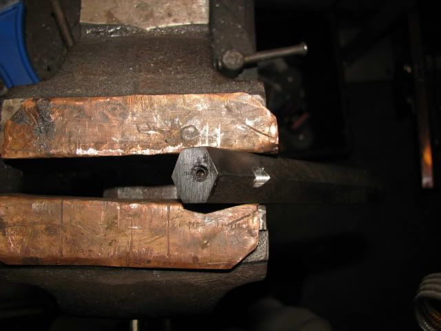
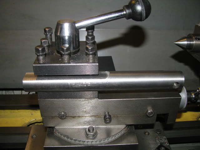
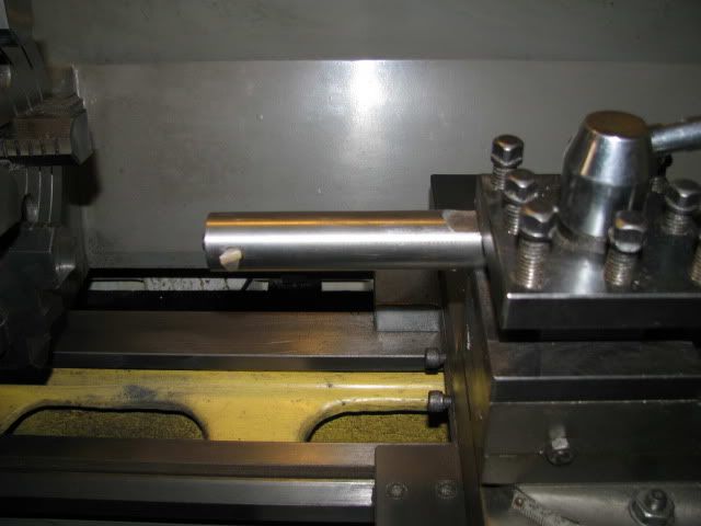
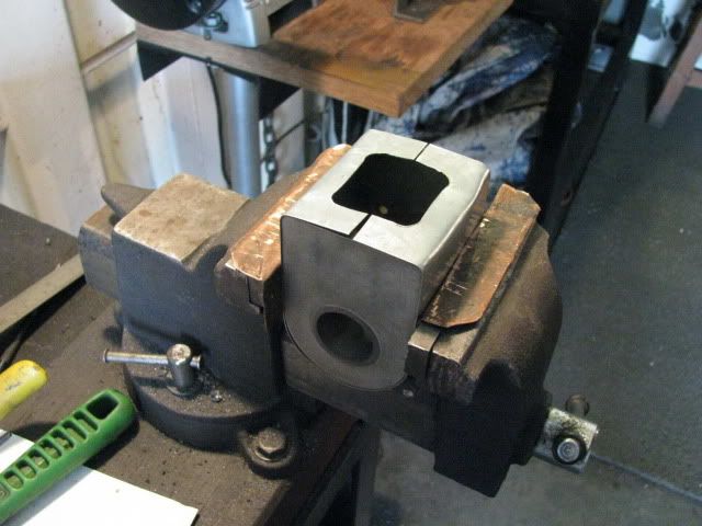
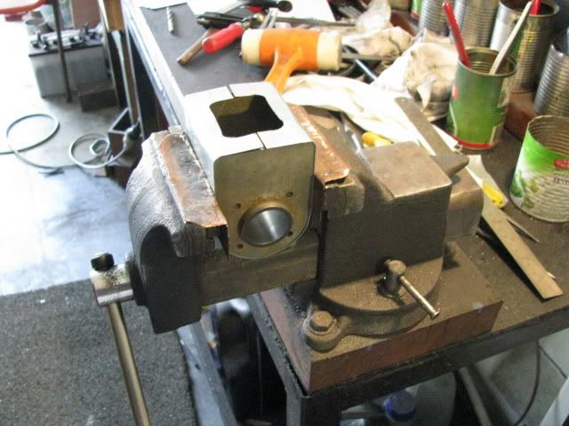
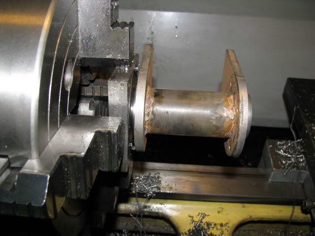
Could you mount your cylinder to the saddle of your lathe and use a between centers boring bar. Perhaps using an angle plate in place of the top slide? Those old "Model Engineer" magazines are always showing setups like that. Don't know if your lathe can do tricks like that.
Dave

 
Dave

I thought about that idea as well but Bob, like me, has an AL320G which for all it's good points does suffer because it has no tee slots on the saddle so short of drilling and tapping holes into the top of the saddle I doubt whether there's an easy way of doing that - which is a pity as it would solve the problem.

Rgds - Gavin
 
Dave S, Dave W, and Gavin,

Thanks for all the suggestions. We had a quick dash to Aldinga to see a man about a tile so no play today.

I will try the bigger bar 1st and then Dave (Steamers) packing pieces. I have already taped some shock absorber rag around the cylinder and will soak it in oil and see what happens hopefully tomorrow.

Best Regards
Bob

Edit - I could probably mount it from the tool post using a jig but they say that laziness is the first sign of genius and I certainly qualify for the 1st part.
 
Blow me down one of the freight forwarders lost a 26000l tank. :mad: Whats worse they insisted they had never seen it. :eek:

Guess what, they actually loaded it on a ship and now it's on it's way to California. Only took 3 1/2 hours of phone calls visits and faxes to find it.

So this is a work in no progress.
1018.gif


Best Regards
Bob
 
I can understand that, I'm always losing my 26000 litre tanks. Generally I have to look down the back of the workbench to find it. Suggest to the forwarders that they put a label on it next time so it stands out.
 
Gavin and Rob,

Thanks for your continued support and interest. :bow: :bow:

Well, for once I guessed correctly, the boring bar was the problem.
smiley-happy036.gif


A quick and dirty 3/4" boring bar.

IMG_0692.jpg


The cylinder after boring.

IMG_0695.jpg


Drilling the tapping hole for the cylinder lubricator pipe.

IMG_0696.jpg


It's raining here today so no work outside guess I can have my Grandpa's afternoon nap.
smiley-sleep013.gif


Have a UBEAUT weekend.

Best Regards
Bob


itsa beauty.

nice bore.
 
very nice work Maryak, I follow it with interest

 
Good to hear the simple fix solved it!....and you got another boring bar in the arsenal to boot!

Bore looks good!

Dave
 
Kevin, Ariz and Dave,

Thanks guys for your continued support and help. :bow: :bow: :bow:

Best Regards
Bob
 
Hi Bob,

I can see that a hex bar is held in a vise...and I'm assuming it's 3/4" from what you said.

Could you tell us a little more about it? What makes it a boring bar? What you did to make it a boring bar? How you mounted and used it? I hope this isn't too newbie.

Thanks.
 
No problems Zee,

I'll take a few boring pictures today and get back to you.

Best Regards
Bob
 
Another great and interesting build. Engine is looking great.
 
Zee boring bars for Zee programmer.

A selection of boring bars.

IMG_0697.jpg


1. Commercially made with a small carbide insert silver soldered to the body.
2. Ground from a solid piece of HSS.

The rest are of various sizes. A couple have holes at right angles and a couple have oblique holes to provide for boring and facing when a specified depth, (or blind), bore is called for.

IMHO when boring the trick is to use the fattest shortest bar that will fit the hole + depth and leave a bit of room for the chips to escape, (The fish stay put).

Front and back view of a boring bar mounted in a 4 way tool post.

IMG_0698.jpg


IMG_0699.jpg


All my home made bars use round HSS from 1/8" - 3/8" dia and the HSS is secured in the bar by a grub screw at right angles to the hole for the tool.

IMG_0700.jpg


Hope you found this useful.

Best Regards
Bob
 
Bronson,

Thanks for your continued support and interest. :bow:

Today saw the water jacket constructed.

Some sheet metal for the jacket.

IMG_0701.jpg


The water jacket in place around the cylinder. I plan on leaving it like it is whilst I make a drilling jig for the head and cylinder interface. Hopefully it will develop a bit of shape memory, making it easier to solder.

IMG_0702.jpg


IMG_0703.jpg


Best Regards
Bob
 
I guess the old saying, "The Miser Pays Twice," bit me today.

I could not find a piece 2 1/2" dia, but on hunting around I found a piece 1 1/4" x 4" x 10" so I hacked a lump a little over 2 1/2" square off it.

It cut OK in the hacksaw but when it came to machining it in the lathe, I had hells own job, pretty tough stuff. As we are not on a production schedule I persevered, but the jig will take quite some time to complete. Ah the joys of mystery metal.

The jig lump in the lathe.

IMG_0704.jpg


Roughing out the cylinder spigot.

IMG_0705.jpg


Fun Fun Fun.

Best Regards
Bob
 
Maryak said:
I guess the old saying, "The Miser Pays Twice," bit me today.

That saying rings true all too often. How often those simple little fixturing jobs grow into monsters with their own agenda :wall: I think I take them for granted sometimes, not concerned about making something for "keeps", probably not being too particular about all the tiny little details that make such a difference to the process...
 
Hi, I'm back ::)

This past week has mostly been spent at home due to a nasty little gastro bug. After re-hydration and some fancy antibiotics, things are back to normal.

The jig is ready for drilling after almost 4 hours of fiddling. :mad:

The jig mated to the cylinder.

IMG_0718.jpg


Hacking off surplus bits.

IMG_0719.jpg


Machining the major diameter to match the head.

IMG_0720.jpg


Ready for marking out.

IMG_0721.jpg


Best Regards
Bob
 
Back
Top