- Joined
- Jan 24, 2009
- Messages
- 554
- Reaction score
- 123
Maybe that's not the right term.
I'm working through various aspects of this hit and miss stuff and, through
this board and others, have pretty much figured things out in general.
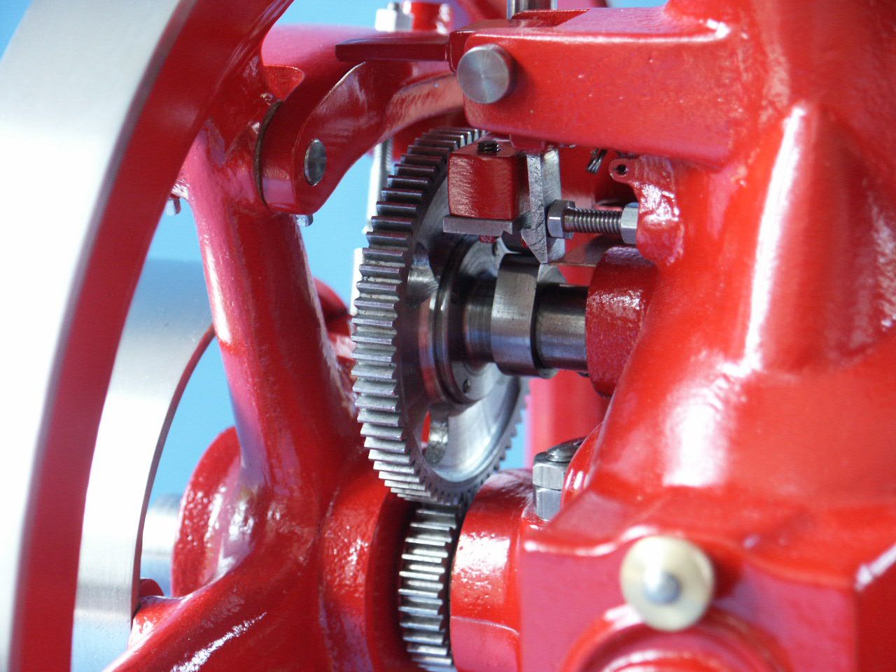
There is, however, one detail that I don't have firmly in my mind; the
various mechanisms use to 'lift' the push rod (?) to hold the exhaust valve
open. I've got the flyball governor thing but there seems to be more than
one way to actually hold open the exhaust valve.
I've read the Tiny IC thread (what a beautiful little engine!) and the way
that GaillnNM rigged it to be a hit and miss. Nice and simple. But I know
there are other ways and I'd like to familiarize myself with them.
Most photos I see don't show that detail.
Can anyone direct me to drawings or photos of ways they have done this? Maybe to posting here or on other boards? Or to on-line plans?
Thanks,
Pete
I'm working through various aspects of this hit and miss stuff and, through
this board and others, have pretty much figured things out in general.
There is, however, one detail that I don't have firmly in my mind; the
various mechanisms use to 'lift' the push rod (?) to hold the exhaust valve
open. I've got the flyball governor thing but there seems to be more than
one way to actually hold open the exhaust valve.
I've read the Tiny IC thread (what a beautiful little engine!) and the way
that GaillnNM rigged it to be a hit and miss. Nice and simple. But I know
there are other ways and I'd like to familiarize myself with them.
Most photos I see don't show that detail.
Can anyone direct me to drawings or photos of ways they have done this? Maybe to posting here or on other boards? Or to on-line plans?
Thanks,
Pete