High speed CNC spindle

Home Model Engine Machinist Forum

Help Support Home Model Engine Machinist Forum:

This site may earn a commission from merchant affiliate links, including eBay, Amazon, and others.
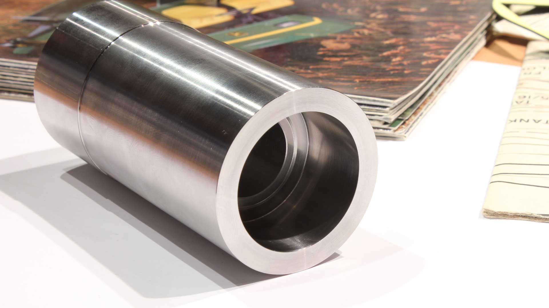
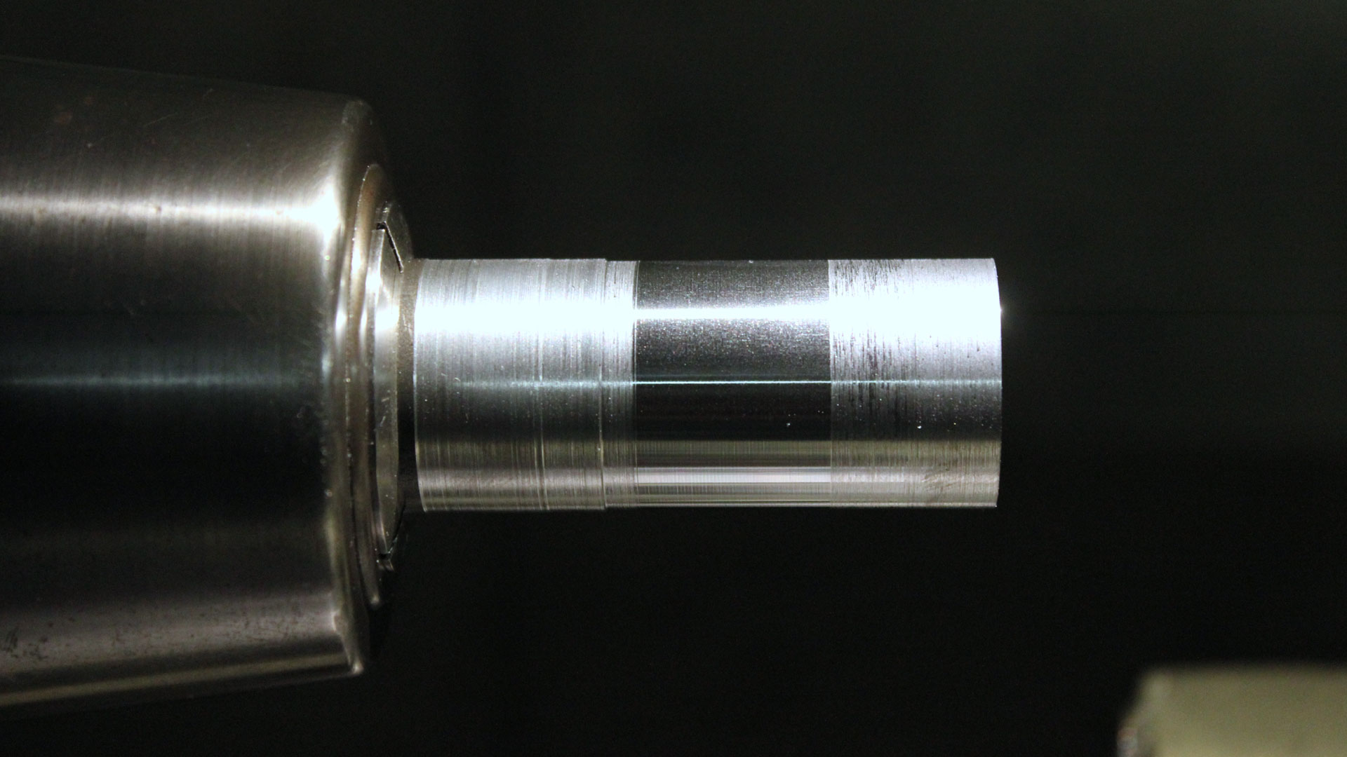
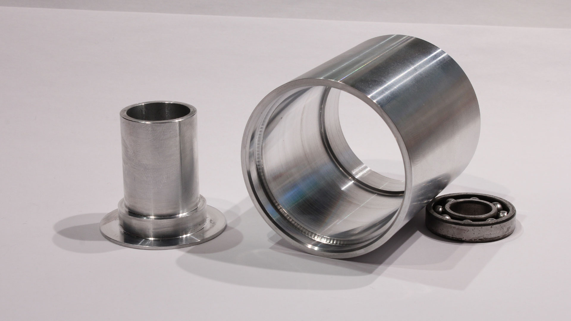
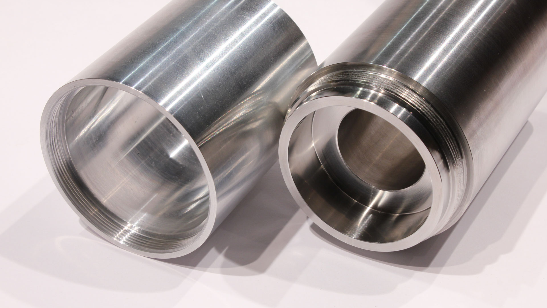
My concern is mostly whether or not I have taper in the main bearing bore. I've fit bearing bore to said bearings but I don't want touch these bearings until they are ready to be installed. They are high speed spindle bearings. The plan is to shrink fit the bearing, which is easy, but the tech spec calls for +4/-3micron on the diameter. I can't claim to be that good, but I'm going to try to get close. Right now i've left plenty of material to practice. The telescoping gage is tricky to use, I might try polishing the ends before giving up on it.
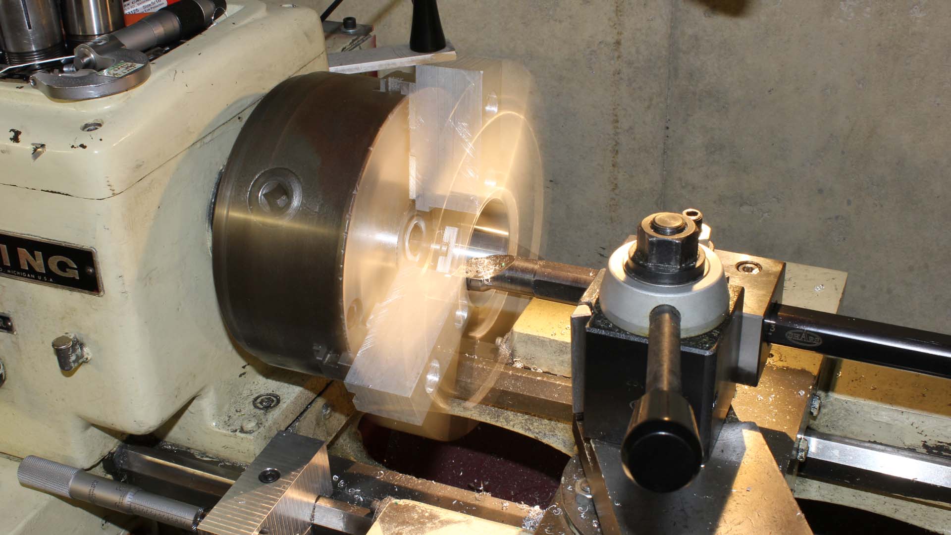
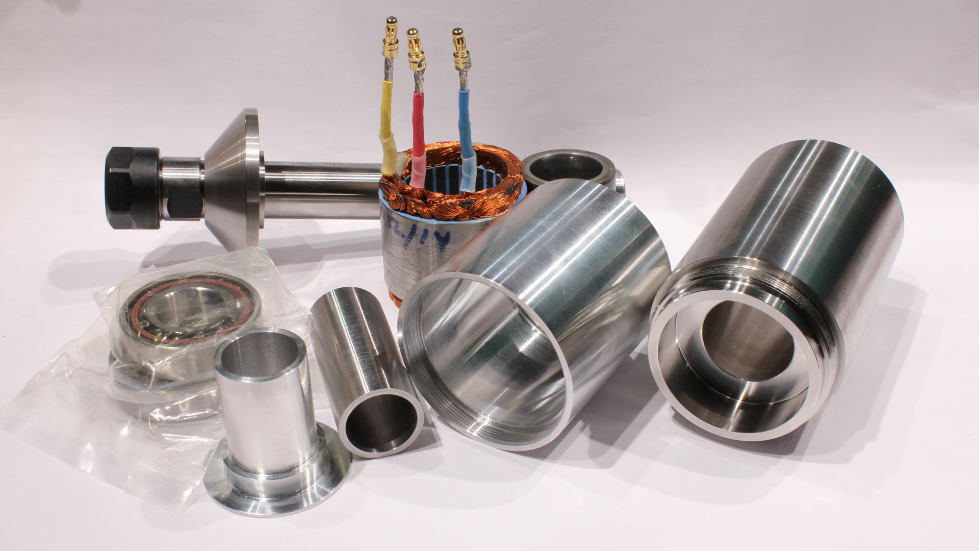
 
One method you may want to consider with the telescoping gauge is to take a number of readings, say 6, toss out the high and low, and average the rest. That may not get you where you want to go, but it should be darned close.

The best internal bore gauge I've ever used is one of those three-point, carbide-anviled internal bore micrometers. When I needed 12 bores lapped to 1.0000", the thought of using telescoping gauges for that was not appealing, so I bought a 0.800" to 1.000" bore mike. But they are SO expensive.

Maybe someone has had some experience with one of those less-expensive bore gauge kits that use a dial... I think they are used mostly by guys boring IC engine cylinders.
 
I did just buy one of those bore gages off thEbay yesterday, Mitutoyo 545 series. I will probably still need to get the proper anvil for it, but for $50 for a $500 bore gage another $50 in anvils is OK. It's just the time where this part is sitting in the chuck that is annoying. Luckily, I have some work that won't require the lathe.
 
I'll be getting back to this shortly. I ended up buying a brand new Mitutoyo 511 bore gage. Ouch! Should be here in the next day or so. The Ebay deal never showed up. The first time I never got an item from a seller.
 
I'm definitely looking forward to your progress. A good spindle seems to be one of the most difficult parts of a CNC build. The choices end up being...

1) Too massive & heavy
2) too expensive
3) underpowered
4) Cheaply-made and imprecise

Trying to fix all four of these and stay within any sort of budget is a real challenge.

Did you look at the Sherline ER industrial spindle?
 
OK. Gage arrived today, bearing bore turned out dead nuts to the .0001" with no discernible taper. I'd have to say it was more luck than my experience, unless I can pull it off on the other end. If I start believing it was all me, I won't have any excuses for not being more productive.

One end of the housing is done. More tomorrow.


Swede, I did not look at those spindles. For the price I'm sure they are worth it. And, if the above doesn't work......
 
The housing is nearing completion. After the first end was done I needed to turn it around and make sure things were square. I didn't want to mar the finish as well. Soft jaws are the answer. These are a set I made. By the way, I'm not going through that again, to save maybe $25. This is a faux action shot of turning the jaws, they were already cut.


And the finished jaws. These are also good for holding short parts by boring shallow to seat the part. in this case I wanted a good grip.


After putting the part in I checked it with a .0001" dial test indicator on the OD. Near the jaws there was virtually zero runout. Out where the part needed to be cut off I had .0015". A couple taps brought this to .0001 TIR. Now the real test, after breaking a cutoff tool because I didn't check square, sawing off by hand, and resetting the part in the jaws, I began turning the other end features. The through hole in the housing had been bored just over 3" deep in the first setup. Once I broke through to this bore, I put the indicator on it, to find it was .0002" TIR! Great things were looking up at this point. The rest of the machining went without a hitch but for a inserts wearing. I hit the dimension within a couple tenths for the opposite bearing bore, so the first one wasn't much of a fluke. This lathe and operator seem to know what they're doing.

The body without threads, those will be CNC milled, yeah crazy I want metric threads, and this old American iron didn't come with a metric threading set. It also still needs holes for the bearing cap in the other end.


Greg
 
Looking good! Anyone who has tried it knows that large and deep bores are very challenging to execute so as to not have at least some taper.

I like your soft jaws, good idea for a project like this.

The Sherline ER cartridge spindle is a bargain for what you get, IMO, but it will probably not rival your finished product.

For anyone interested: http://www.sherlineipd.com/spindles.htm For less than $200, you can get both cartridge, flanged, and dovetailed spindles with an ER nose rather than a MT. I have one that I was going to use, but it was just a wee bit too light. Sherline also has instructions for bearing adjustments that would allow 10,000 RPM if needed.
 
I stayed away from the machines while I was sick and my head cloudy. I hate to think of what might happen if I made a mistake while working with one of the machines in that condition. Today, I made the bearing spacer tube that fits between the bearings. I bought some Sandvik inserts and they are very good about specifying feeds and speeds right one the box. So unlike usual I decided I was going to check to see what gives the best finish. The stock I had happened to be 4340 annealed. The recommended surface speed was pretty high to I set up for low end at ~1500RPM, but started a bit below, maybe 1200. I set my feeds so I could easily change between about .001, .002and .004/rev. I tried a few lighter cuts without at any luck at any feed rate. The cuts were the typical draggy cut I had been seeing in most of my steel work. Heeding the recommendation, I dialed the speed up to 1500RPM and .008 DOC. As I switched through the feeds I was blown away. The chips turned blue and the finish mirror-like. Now at 1500 RPM and .004/rev, things move along pretty quick. This part was 2" long so it was not a blink of the eye, but you had to be on the ball at the end of the cut.

Greg

 
A couple more parts today. On the left the part the motor rotor will be pressed onto. On the right the motor housing. I picked up some chatter on the ID of the thread relief, it's reflected on the shoulder in the photo. I made some last minute changes to these parts after verifying the dimensions of the stator assembly. I drew the stator from a different but similar motor and this one had larger endturns (wire). Fortunately it didn't have much impact on the overall layout. I still have to pick up a few things. Bearing preload spring, probably some bearing grease, magnets for the hall sensor trigger, some 6004 bearings to use during balancing, and some teflon.

If I get around to threading tomorrow on the mill I'll post a video.

Greg

 
hey Greg

What kind of lathe are you using?

Dave

 
It's an old Clausing 4904 that looks like it came out of a highschool. I've been very happy with it, and the tolerances and finishes I've been seeing lately have made it a great investment. The 4900 series are similar to the 5900, but were made smaller with a 10" swing. I guess most of them did end up in training environments, this one has scars to prove it. Unfortunately, parts are scarce and expensive. I'm in need of a steady rest, and they run about 400USD, IF you can find one. That might be another project if I can't source one before the job needs to be done. Had I more space I'd buy a complete lathe for spares or backup, they aren't all that unusual.
 
Check out Tools4cheap.net

He may have something that will service your steady needs.

Dave
 
I did look at those last week. There are some with a separate base. Making a base to fit my machine would be much easier. I will look into those before I do anything drastic. Thanks for reminding me.

Greg
 
I've got one of Jeff's steadies on my Logan ( Logan steadies are almost unobtainium....when found their ridiculus) Jeff's steady works great....needed a little bit of minor clean up and attention but it was all small stuff you find on most far east products....burrs and cleanup. Mine has a seperate base that came with it. Your right, a base would be easy to make

You can see it here.

http://www.homemodelenginemachinist.com/index.php?topic=7692.0

Dave
 
I'll get back on this tomorrow. The threading toolpath is ready, but I got caught up in checking tram on my mutt cnc mill and did get very far yesterday. Today, I chased down an Emco Compact 6 CNC lathe. Another project... It needs a complete control retrofit. But, this will be far better than converting a chinese lathe, which I had been putting off until I could get good ball screws at a reasonable price.
 
I got a bit sidetracked with the new lathe. I finished the threading today. Threads were cut by helocal interpolation in my CNC mill, the same mill this spindle will be installed in when done. The two parts fit together with a very close fit. This was accomplished by milling the thread into the stainless body part first, then adjusting cutter compensation while cutting the aluminum motor holder until it fit. I had made the thread relief too small in the body so it needed touching up int he lathe. I checked the fits of the bearings in the body and the rear floating bearing got tight a little more than half way into the bore. A bit of sandpaper while spinning in the lathe loosened the fit.

 
Thanks! I really should get this finished before getting too involved in another project.

This is pretty much what's going into this spindle. A few parts are not in the photo. Most notably, the bearing clamp ring is missing, hopefully my daughter didn't re-appropriate it for her "collection". It's probably on my desk somewhere, it wasn't that long ago when I saw it last.

Next is drilling and tapping the holes in the body for the clamp ring.

Greg


Latest posts

Back
Top