High speed CNC spindle

Home Model Engine Machinist Forum

Help Support Home Model Engine Machinist Forum:

This site may earn a commission from merchant affiliate links, including eBay, Amazon, and others.

mu38&Bg#

Well-Known Member
Joined
Jan 17, 2009
Messages
1,437
Reaction score
142
So it's time to replace the spindle in my Ebay parts CNC mill. I work on mostly small parts with 1/4" and under cutters so I decided on a fairly high RPM design using a brushless motor from the RC world to drive it. I have an industrial type controller but rated at only 500W, so I may just use an RC speed controller to operate it initially. I began today with the hope of getting along quick, but so far have made only a small dent in it.

An almost perfectly good motor was stripped down to the parts I need.

 
If you haven't sawed through 2.25" 304SS round bar by hand you haven't lived! After a lot of sweat, I have a 6" long stick of said material in the chuck and will begin cutting some parts. As I was already thinking about surface finish, I did some tests the on OD of the bar. Steel inserts work OK, but for the finish pass I decided to try an aluminum insert. All I can say is the finish is much better than I expected and it take off as little as you want. This should work very well for finishing the bearing bores.

I'll post a sketch of the overall layout later.
 
I'll be the first to admit I know less than nothing about computers or CNC, But if you haven't already thought of it I'd design and build your spindle to allow the use of some of the smaller series of ER collets. Obviously balance and dead true running will be a requirement at those speeds. Are the bearings your using designed to take the side and end forces?

Pete
 
The design uses a pair of angular contact ball bearings in the bottom and a single angular contact bearing in the top. The tool holder is a Chinese ER16 straight shank holder. Motor is a Neu Motors 1912/1Y. The rest is going to be made. There are a few threads over at CNCzone that get into the design aspects. This is what it will look like.

 
That's the way a spindle should be made - with two close coupled bearings as close as possible to the load and set to take out longitudinal lash - the tail end bearing merely acts as an outrigger to support and allow expansion and contraction of the spindle.

A common design error (my Chinese lathe and minimill) place the bearings at opposite ends of the spindle - so if set to zero lash - then as the spindle heats up it loads the bearings rapidly wearing them and introducing lash at stabilised temperatures once again.

Some industrial NC machines (Gildermeister) use angular contact tandem pairs which require unbelievable precision for both to carry the load.

2c - Ken
 
dieselpilot,

Some thoughts based on my own current experience of building a CNC HS spindle:

  • [liHow do you intend to hold the spindle - this is the 'right' moment to build in lugs, ears, or any other type of attachment - having a near perfect run out but a wobbly or not truely aligned spindle is not helpful]
  • your base design which puts the motor at the back - if you move the motor to the middle and move the top bearing to the very end, you will have a stiffer spindle assembly for side loads
  • if you use a RC speed controller prepare to do some electronics to make it compatible with Mach3 - the servo/RC controllers expect a 1-2ms pulse every 20ms where 1ms = no speed and 2ms = full speed, whereas Mach3 outputs a true PWM signal where 0.2ms = zero and 19.5ms = full speed. The two are not compatible and require some playing to get them to work together
  • Power supply - I am currently (for testing) using a small car battery to provide enough amps to drive my ~500W outrunner since the power supplies I own did not like the peak start current - even with lots of C to help

I am watching your progress with interest and may even get around to reporting my own progress here...
Simon
[/list]
 
A few years ago I picked up a Myford OD grinder that was missing the workhead. I built a workhead spindle from scratch and it has worked well so far. I agree with KenI that there should be 2 angular contact bearings on the tool end next to each other to set end play and 1 bearing on the other end as support for the spindle. Some high strength spindles use more than 2 bearings on the tool end but that is probably over kill.
One of the toughest jobs is to machine the bores for the outer races true to each other. The tool end will be bored for the 2 angular contact bearings and the other end of the housing will get bored for the support bearing. These bores and their shoulders must be true with each other. Any misalignment will create heat when running and assembly problems. I think maybe you could rough bore the housing first then fit it to an arbor between centers to finish each ends bores to keep alignment. I am quite interested in this project as I would like to do the same so keep us posted. my 2c, Dave
 
Yes, I understand I have a bit of compromise by putting the motor on the end. I had a version drawn with the motor in the middle, but it complicated the components and assembly quite a bit. This makes it easier to build as the body is only ~90mm long. Chances are this would never see a 3/8" endmill except for light facing. Mounting on the machine will be the typical method for such spindles, a bored block with screws to clamp. The intention is to complete this in the next day or two.

Bearing suppliers tech specs describe numerous ways to assemble spindles. I agree though that is thermal expansion is not accounted for in material selection, a rigid system like Ken describes is bound to fail.

Back to the shop!
 
I had a battle the PC today. I didn't print the drawings yesterday and it wouldn't boot today. Nothing new the PS for this particular Dell is trash I have 3 bad ones now. I was swapping 2 everytime they went down for some reason after a while resting they would work again. After days or weeks, after shutting down it won't give a "Power OK" signal after POST. So, today I fixed it semi-permanently by rewiring an ATX PS to meet the proprietary Dell connector standard. The only thing I don't have is fan tach signal from the PS. It runs with an error on boot, so I'm not going to complain for now.

Anyhow, I only manage to get the cone for the spindle shaft made today. Photos tomorrow after I get it mounted on the shaft and finish turned. Turning that 304SS is slow going.
 
I'm really looking forward to seeing how this comes out. I'm currently in the process of looking at spindle options for mt CNC build, and have been eying those ER16 chucks. What size controller do you plan on using?
 
Same here but I'm looking at something with speeds from 4,000 up to 10,000 max but enough power to poke a 5mm drill thru 6mm of steel.
Does this sound too unreasonable ?

John S.
 
If you need torque, a reduction stage is probably necessary. I've seen a few spindles made from "outrunner" motors, which would have 2-3 times the torque of what I'm using, but I'm unsure of their capabilities. I looked at some machining power calculations before proceeding with this. I've been meaning to put it into a spreadsheet, but there are online calculators available.

http://www.mapal.us/res_calculators.html

I have an early start today, so should have some parts by dinner.
 
Dieselpilot, I'm curious, why did you reject the numerous eBay spindles that come in various power ratings, from 500W to 3kw? They seem to be a bargain. I wish they had been around years ago when I was struggling to find a suitable spindle for my own CNC build. In the end, I tried two different spindles - a Sherline ER-16 spindle, and the better answer, an eBay-purchased KaVo HF spindle.

Anyway, the spindles available that I refer to... here's a typical one:

http://cgi.ebay.com/ws/eBayISAPI.dll?ViewItem&item=180662235123#ht_10291wt_1139

Even if you want more precision, something like this could be a "kit" of parts capable of being upgraded with ease.
 
I remember your build of the little mill. It's why mine exists today. I've looked at those ebay spindles and thought pretty hard. I've heard that the aren't up to milling. One of the listings for Chinese spindles clearly states it's not for metal. Some time ago the same seller recommended them for cutting metal. They are a bit lacking in specs. The only step I'm really concerned about is balancing this thing. I don't know, maybe I'm digging a big hole. It might not work, it won't be the first time. Only one way to find out.

I forgot to verify the ID of the cone before cutting it off the bar. There was a bit of taper and need to be fixed. I decided to make a lap so that took up some time today. The cone was a shrink fit on the shaft, but I augmented it with anaerobic bearing mount. After it was on the shaft I did the finish passes to true it to the shaft. I have to put a 6 jaw set true chuck on my shopping list. I also made the bearing clamp. Hope for smooth sailing tomorrow with the body. That will be done in machined soft jaws.

Greg


Progress was slow today. The nose bearing bore is almost done. Then the body gets turned around and put in the soft jaws I mentioned to machine the other end. If everything goes well, it should be dead nuts. All I had for my big boring bar were aluminum inserts. They work well at low feed rates. Some of the steel inserts out there have fairly high rake.

Greg

 
Well, I backed myself into a corner. I thought my dial bore gage reached to 1.75" but it's a 1.5". I can't get a consistent reading on a telescoping bore gage to see what my bearing bore is like. I might have to wait until I can beg, borrow, or :'( buy! a dial bore gage.

 
Swede said:
...numerous eBay spindles that come in various power ratings

Sorry for the off topic, but your ebay link was very interesting. I had no idea those were available at that price. Do you think spindle / power box/vfd combo's like this would be adaptable as mini tool post grinders like for use on lathes? Im guessing the loads would be similar (or lighter?) than what it would see in CNC-mill plunging & routing, no?

spindle inverter combo.jpg
 
Petertha - having no experience with these inexpensive eBay spindles, I'm a bit hesitant to say "go for it," but the price is soooo right. These things replicate unitary 3-phase HF (high frequency) spindles in appearance if not function. A German or similar HF spindle with similar characteristics (up to 50,000 RPM, ER nose, 0-400 hertz) would easily run $3,000 U.S. or more, possibly much more.

If you do want to give it a try, I'd go with an air-cooled variety, fabricate a guard for the wheel, and above all, be sure you use good wheels and balance them well. At 20,000 to 30,000 RPM, even tiny imbalances would shake it like crazy and possibly cause damage.

My gut feel says they'd do good work as a grinder spindle. Be aware that these bodies are pretty hefty diameter wise, so you'd have to also fabricate a mount. Using pullies and a belt would defeat the purpose, as you'd need another precision spindle for the wheel portion. Anyway, if you try one, it'd be very interesting.

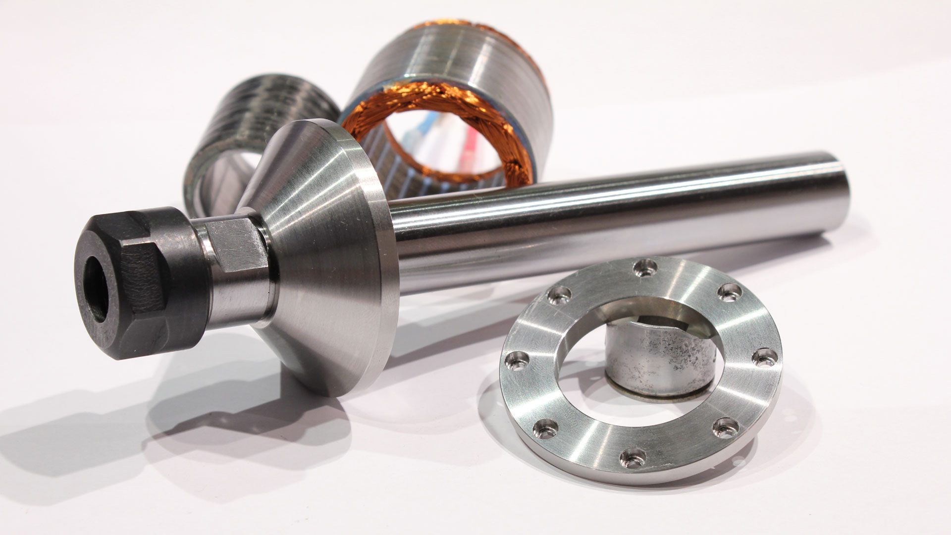
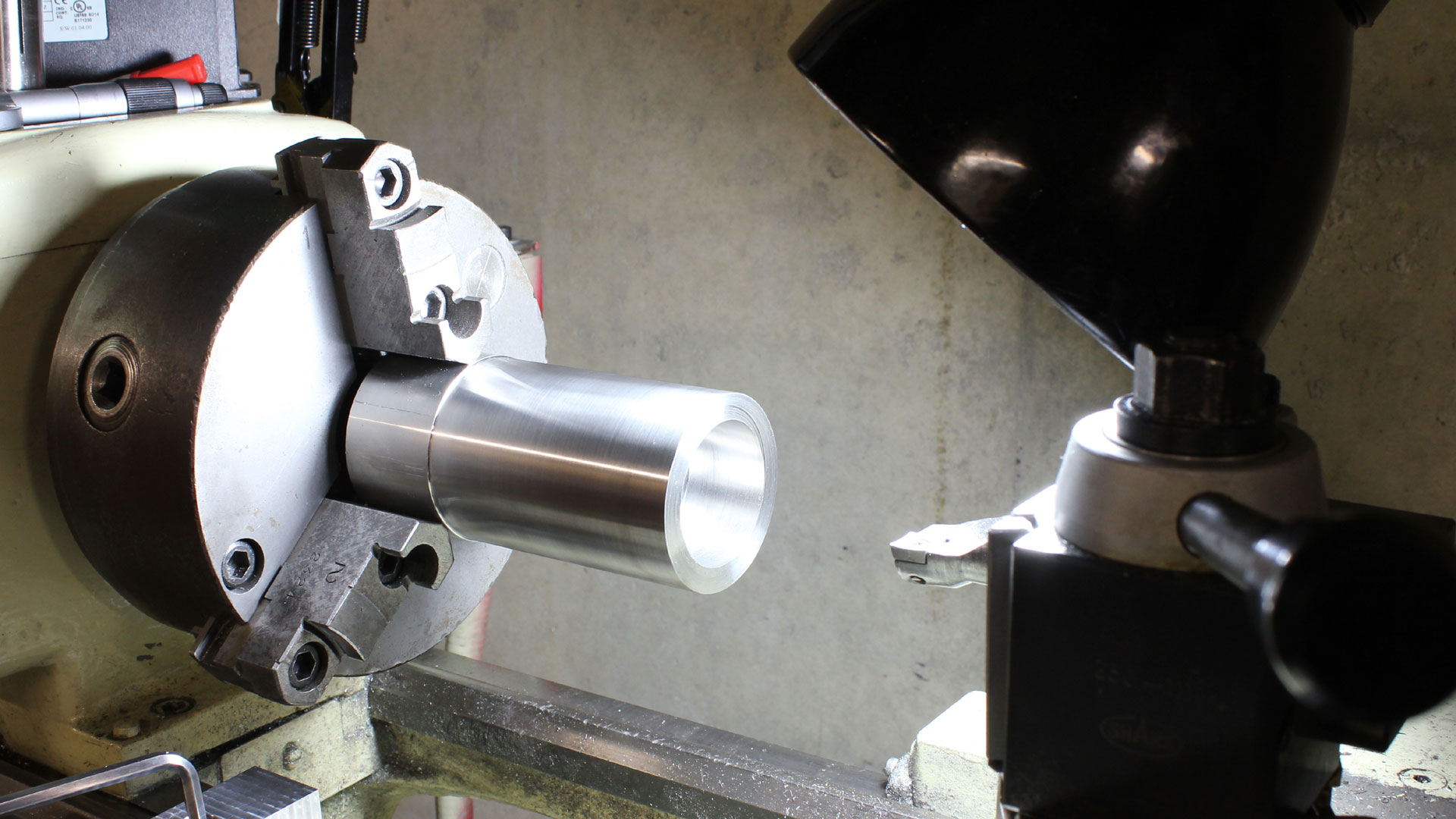
Greg - Your components are looking very nice. Odd that your telescoping bore gauges aren't working for you. I assume the bore is for the bearing OD? What tolerances are you seeking? Have you considered sneaking up on the bore you need using the actual bearing as a gauge?
 
I have one of these spindles on my home CNC router. Mine is the 2.2kw version which holds an er20 collet. Don't expect much out of these cheap Chinese spindles, mine has a run out of 0.04mm so I am hesitant to run it at full speed with a smaller cutter. The bearings are far from being any German or even Japanese brands and more like Chinese crappy second grade bearings but they are replaceable, there is a thread some where on CNC zone on how to dismantle the spindle. The vfd are hit and miss whether they are missing certain components inside, some were made without the components to activate the on and off control coming from the pc, probably not a biggy to some. I will say one good thing, I bought mine to reduce the noise in my shed, sometimes the router can be running for 5 hours doing an engraving and the noise of a electric router will eventually drive you mad but this spindle is very quiet.
 

Latest posts

Back
Top