High speed CNC spindle

Home Model Engine Machinist Forum

Help Support Home Model Engine Machinist Forum:

This site may earn a commission from merchant affiliate links, including eBay, Amazon, and others.
Frameless brushless motors are how the big boys do it. I recently finished a 14 HP spindle for a big lathe that way.

That looks very sexy Greg....can't wait for the first use in anger!

Dave

 
I too am getting eager to run this spindle. The way things are going, I'd be disappointed if it wasn't awesome.

I spotted the screw holes for the bearing cap in the little CNC mill. Due to the limitations I have now with the spindle it was just a tiny spot. This was plenty to transfer over to the Arboga and drill. I purchased in the last couple months a Tapmatic tapping head. Thread forming taps sound like the best thing since sliced bread so I decided to give it a try. I purchased a few OSG thread forming taps of their least expensive variety. I followed Tapmatics instructions for setting up the feed depth and stop on the mill. It went off without a hitch. The best thing is no chips to clean from the holes!

Tapping video later.


I've also begun assembling some of the parts onto the collet holder to begin balancing it. The balance fixture still needs to be made, but it will be simple.

This is what tapping with an automatic reversing head looks like.

[ame]http://www.youtube.com/watch?v=_CUGz0jXvWQ[/ame]
 
I've assembled some donor inner races of the same size as the actual bearings that will be used onto the shaft. The shaft is assembled with all the rotating components prior to balancing. After balancing the orientation will be marked so it can be reassembled the same way. The balancing fixture will be a simple device. I've read it's possible to do a very fine balancing job without the aid of electronics. I guess I'll find out.


Greg
 
That's just pretty. I mean, really. You've done an amazing job. :bow: :bow:
 
That's looking awesome Greg! I take it your using labyrinth seals?....air purge too?

Dave

 
Thanks for posting that Tapmatic head video... I've waffled over buying one of those for years. Now I want one! :big:

Are you satisfied that the depth of the "V" formed by the chipless tap is adequate and strong? How does it work without creating forces high enough to break the tap? Do you have to drill an oversized tap hole?
 
Thanks for the comments guys! I'm sorting out the balancing now.

Dave, there will be labyrinth seals, but I had not intended to pressurize it. I don't have compressed air in the shop, at all for that matter.

The form tap manufacturers suggest hole sizes based on the tolerance of the thread and thread depth percentage. Recommended hole size appears to be the same among manufacturers. The hole is larger than for a thread cutting tap. This one has a 2.5 thread lead, and they make 1.5 thread lead forms taps as well. I'm not sure exactly what makes these things tick. There doesn't seem to be much of a load during tapping. A form tap has quite a bit more cross sectional area compared to a thread cutting tap. I'm convinced the form tap is a good method for making threads. It seems that the work hardened thread would be very strong. Some of the reading I did implied it's very common in production today, especially in blind holes. It seemed like quite a few guys over at Practical machinist use them, for what that's worth.

The tapping head was kind of an impulse buy. I do some prototyping in my home shop and didn't have a tapping fixture. Rather than add another piece of gear that takes up space I thought I'd try one of these. The tapping heads are sensitive enough that you can run the tap into the tapped hole again, for instance if you didn't set the depth low enough, without damaging the thread. I bought used at a very good price, but I'm not sure I could justify new.

 
The form tap method is a kind of forging, and when you forge, you get strength. It makes sense. I need to give it a shot.

I assume you use these in softer metals... mild steel as well?
 
Running without air will be fine if you can otherwise remove the heat. The amount generated will vary approximately with the square of the speed, so final top speed will be a deciding factor.

If your building a dedicated mount for this spindle, a rugged construction of aluminum may be in order as it will pull the heat away quickly...but again that will depend on how much is generated and how big your sink is....what are you running for lubrication?

Dave
 
This project is held up by me trying to decide what to do about balancing. Realistically it needs to be balanced to G3.5 or better. Sending it out sounds costly from what I've found on line. Doing it at home is possible with some investment in software and hardware. The question is will I use it enough to justify the expense? I might have a favor through somebody, but I don't know yet.

Greg
 
You work looks great but why use 304SS for a spindle? it shrinks and grows with heat like crazy, that stainless will give you fits, that's why spindles are not made from stainless.

If you were making a mixer for bread or cookies dough that runs slow then stainless is perfect.
 
Ehhh yes and no Mike. If he keeps a handle on the temperature rise, it won't be so bad

(Change in length) Delta L = Initial length x Thermal expansion coefficient x change in temperature

The CTE for stainless is 9.6 x 10⁻⁶ or 9.6/1000000 in/in/F


Another thing in his favor is the use of a DU bearing set. For the calculation above, the length of note is only the distance from the front of the bearing to the tip of the tool. The initial length is small...maybe 2" ? It floats behind that up the shaft.

Now the big question...whats the temperature rise?....keep that small and life is good.

Lets say its as I stated and the rise is 30F above ambient

Delta L = 9.6/1000000 x 2 x 30 = .00057"

Now that's from start up to full running condition. I very much doubt you will see that in operation as you will take a roughing cut and then a finishing cut, and the spindle will have warmed up by then and stabilized..it will have gotten to temperature and stopped growing by the time the finish cut comes around.


Now if it gets to be a lot more than 30F or 2"...well...then you may have a problem.....always wise to cool and control the temperature of a spindle.....wait till you have to do it with a spindle that has 8" in front of the thrust bearing! and your trying to hold s micron! :eek:

Dave

Greg,

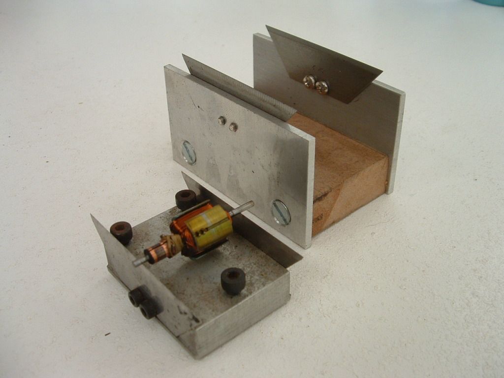
I'll send you a balance worksheet for ISO1940....send me a pm with your email
 
Steamer you make some good points but like I said there is a good reason you never run a machine that has stainless spindles. If it was the right metal we would all have stainless spindles in every tool in our shops but we dont and its for a good reason.

304SS is real bad try and surface grind it and take .0002" and it will warm up and take much more then when it cools its way undersize. its fussy stuff so a high speed spindle would need so cryogenic cooling to stay stable.

I think a 4340 crome molly alloy would be a far better choice.
 
One of the biggest problems with stainless in general is that it doesn't conduct heat worth a bean....it conducts about 1/100 the heat for a given temperature difference as compared to mild steel.

That's part of the reason it grinds so lousy....the heat has no where to go and the surface temperature skyrockets...it grows a lot then!...and you hit the high stuff right a way with the grinder....the grinder digs in and generates even more heat and the cycle continues!

That's what happens when you put a lot of nickel and chrome in steel.....

I recently did some big lathe spindles (9.25" diameter) and they were ground to 20 millionths roundness (no thats not a typo) in 440C at 52Rc....after some proper heat treating and cryo work.

Anyway, I think your going to be alright Greg, but you will probably have to manage the temperature by controlling your heating....cool that bad boy!


Dave
 
Greg, Try ballancing it on a pair of Stanley knife blades - I do this for slotcar motors that run to 120000 rpm.

Sure its only a static ballance - but if it aint statically ballanced then it aint dynamically ballanced either.

On symetrical parts it works pretty well - it doesn't always work but its always worth a try.

Always use brand new blades and be carefull not to knock dents into them which will introduce bias.


Ken
 
Ken

I have been doing this with my miniature turbine (wheel dia. around 20 mm) but instead of Stanley blades, I used razor blades.
I found that this does not work really good and finally balanced the wheel with a self made air-bearing:

[ame=http://www.youtube.com/watch?v=8KOKM5OYm-8&list=UUPL_cxrAxEaBeZmpIcXRdyg&index=3&feature=plcp][/ame]

However, I have been told another way of balancing by a guy who builds rc turbines:
He takes new ball bearings, degreases them completely and then puts the turbine shaft on these bearings.
Then he puts the bearings on the table (supported with V-Blocks) and then uses a (selfmade) vibration motor which is hold on the bearings.

He says that this way, the shaft (including turbine wheels) can be balanced perfectly.


This may be the easiest way for this application?

Cheers Florian
 
Florian - I'm not going to argue - both those methods are better - blades are at best quick and dirty.

When using blades they have to be in the same plane - I set mine against a surface plate and then dead horizontal - also no lube present - clean with solvent - like I said it doesn't work out every time. On slotcar motors I get great ballance about 25% of the time, acceptable ballance 50% and not so good about 25% - those aren't necesarilly good odds. The problem is typically a dynamic one due to lack of symmetry in the windings.
ballance2.jpg

My two rigs - the one in the foreground is better made with leveling screws and shows the patina of a long life - I use it frequently.
I keep them in plastic containers when not in use - they're damn dangerous lying around on the bench.

I've watched the ballancing of a JT9D (Jumbo turbine) a PITB

The blades are first selected so that opposing blades are within a certain mass ballance and no blades in each set deviate by some other value. The hubs are ballanced prior and the whole assembly is ballanced - but because of the fir tree roots you can't get the exact same result twice so there's an awful lot of going backwards and forwards to get it a best you can.

Ken
 
Hey Ken

I did not want to say your method is wrong!
Shurely, the blade-method works and is good enough for certain purposes.
When I tried this, I did put the blades on a window pane to get them into the same plane.

I suppose the problem when I tried could have been that the turbine shaft is made from stainless steel and though I tried to get a good surface, there may be some grooves left from machining...

On the other Side the shaft of such an electric Motor is hardened and polished to get a good bearing surface.

Well, finally I managed to balance my wheel and thats what counts... 8)

Cheers Florian
 

Latest posts

Back
Top