Half Scale Domestic "Stovepipe" build

Home Model Engine Machinist Forum

Help Support Home Model Engine Machinist Forum:

This site may earn a commission from merchant affiliate links, including eBay, Amazon, and others.
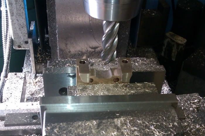
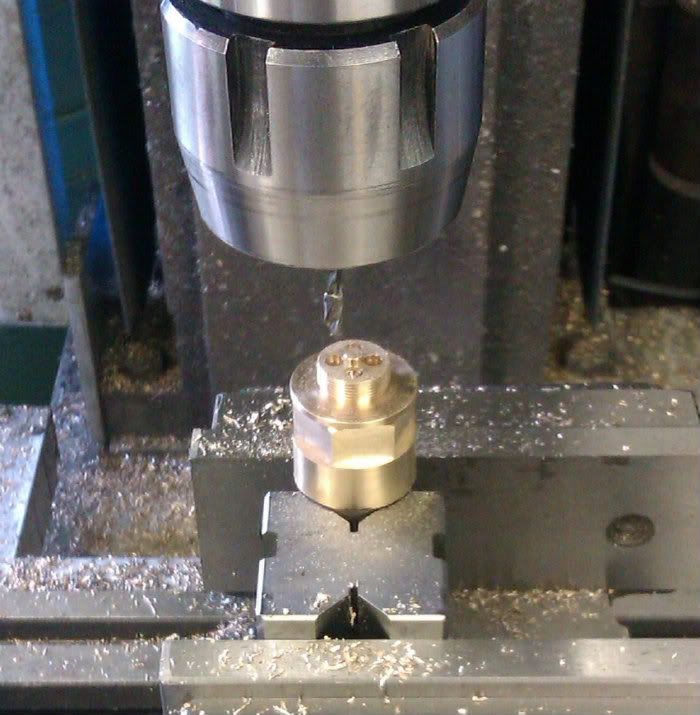
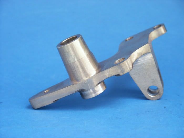
Next I tackled the carb. The top is turned from 1" brass bar and then transfered to the mill to have the hex formed

IMAG0392.jpg


before being upended to have 4 holes drilled which are quite a tight fit.

IMAG0393.jpg


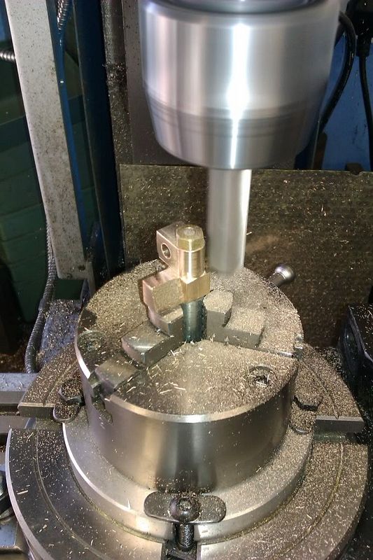
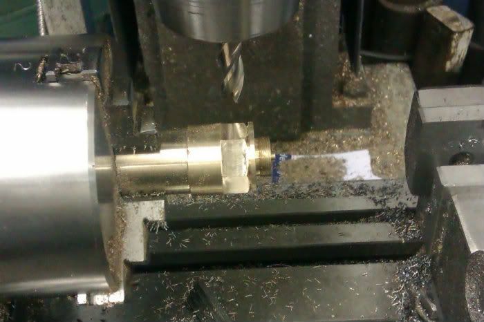
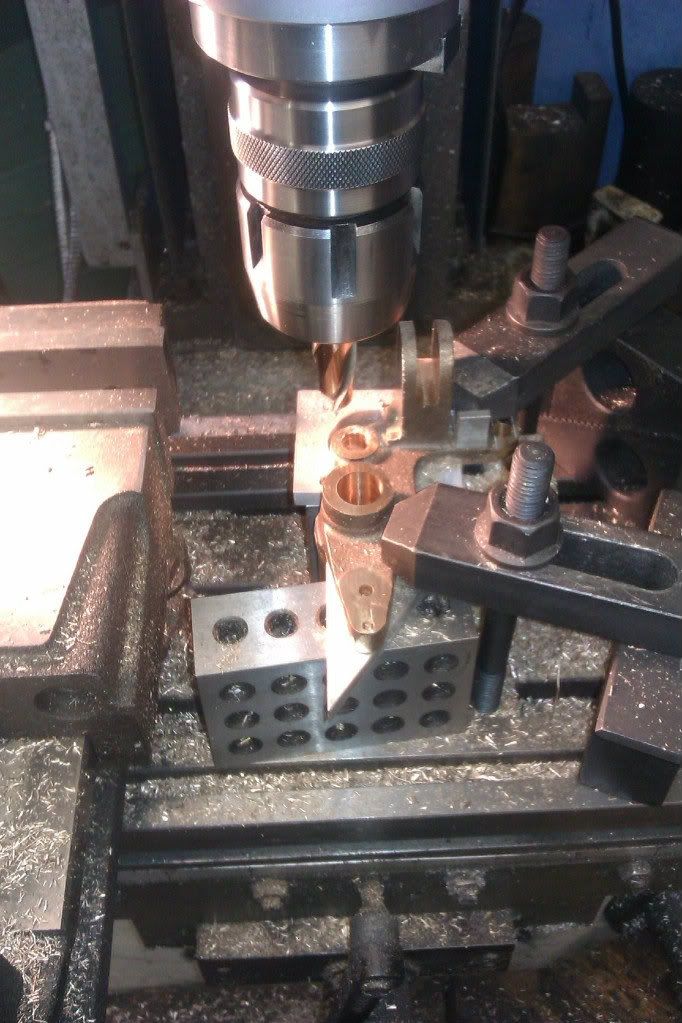
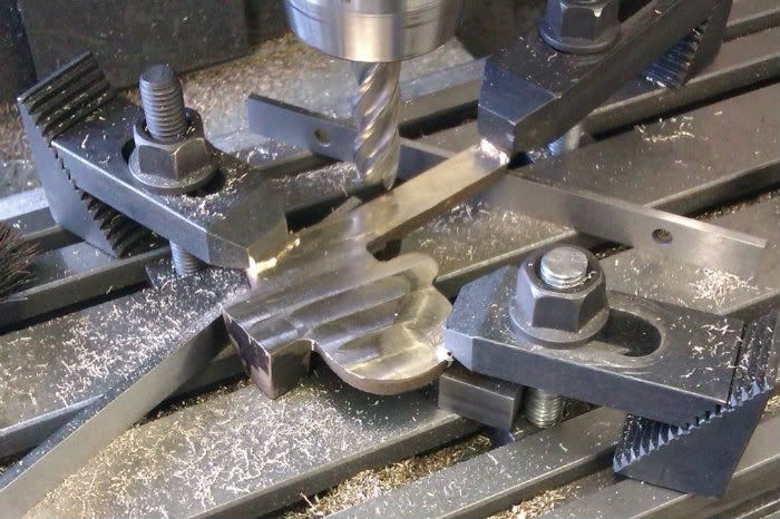
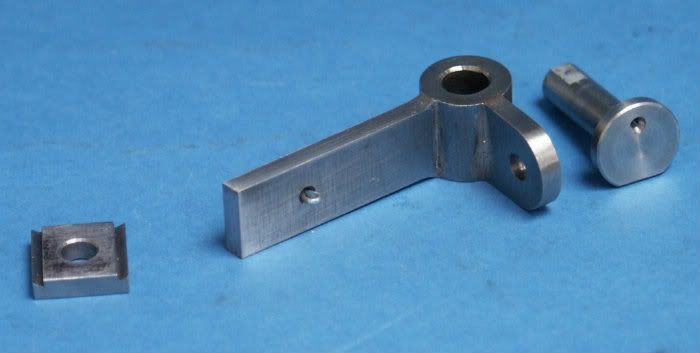
Luckily the bronze casting for the main carb body has a large turning spigot incorporated which makes it quite east to hold so most of the turning can be done at one setting, then moved to the hill for the cross holes and also two rather tricky passages for the fuel.

IMAG0394.jpg


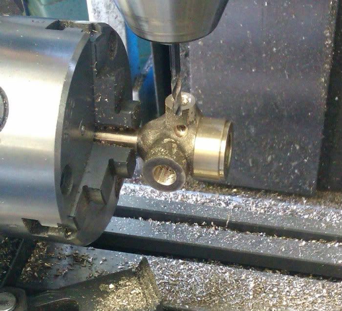
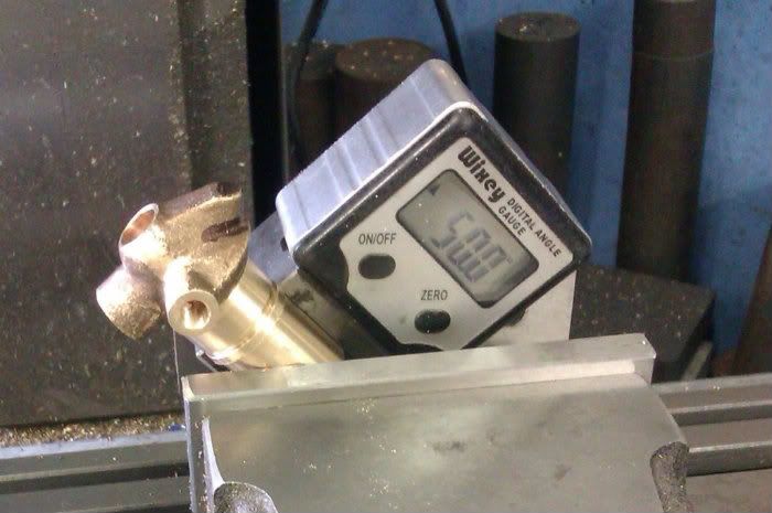
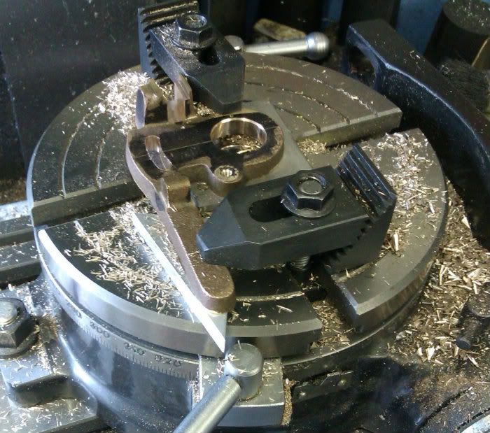
I then machined a matching 1/2"x40 ME thread onto a scrap bit of stock so the bottom hole could be reamed and undercut. I used the same method to hold the body to drill & tap the fuel needle hole at the required angle.

IMAG0395.jpg


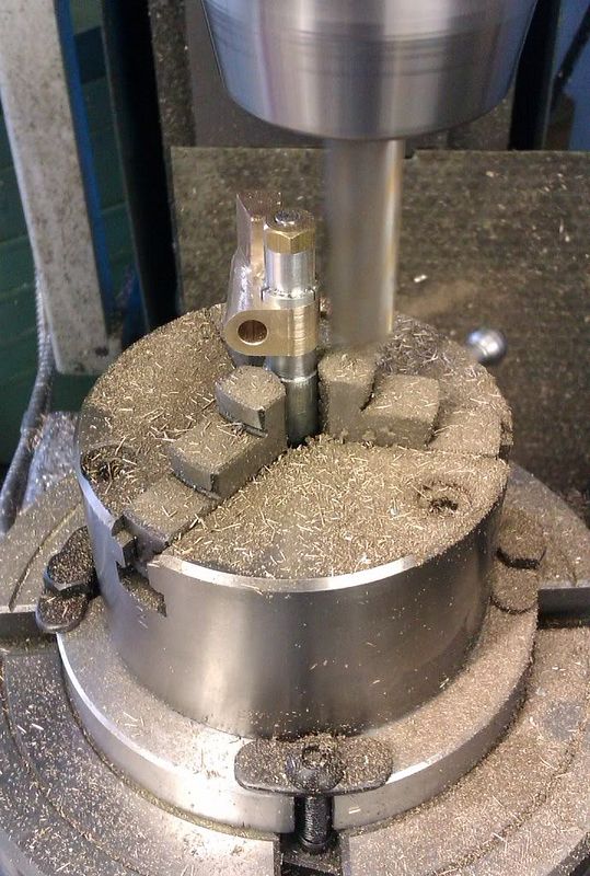
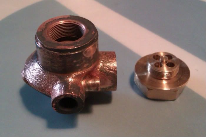
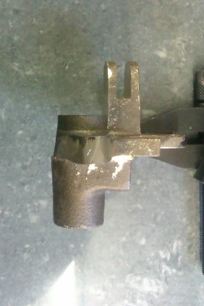
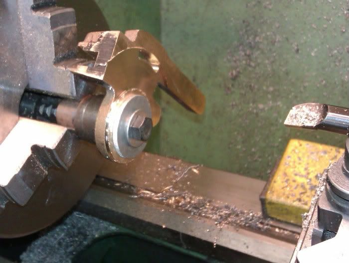
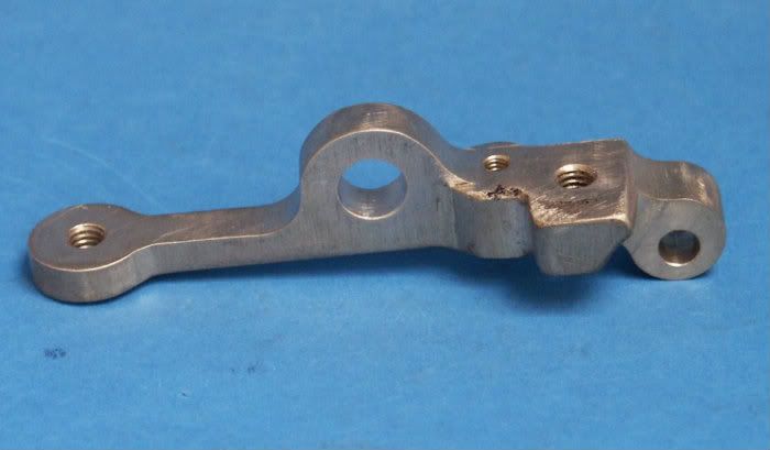
A couple of plugs for the fuel passages were turned from the machining spigot and then silver soldered into counterbores at the ends of the passages, the bits of angle stop the plugs dropping out when soldering, still a bit hot here.

IMAG0396.jpg


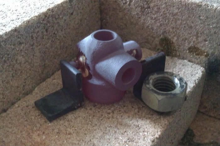
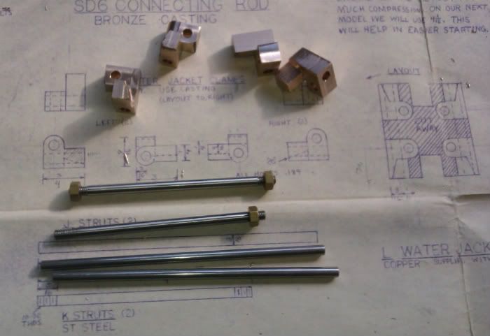
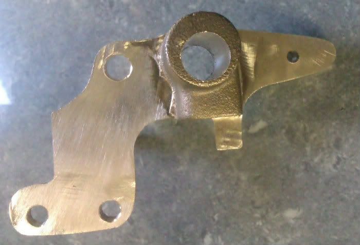
And here are the two parts after a quick clean up, the plugs now need filing to profile and the surface texturing to match the rest of teh cast body.

IMAG0397.jpg


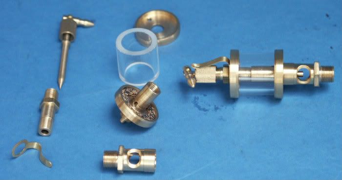
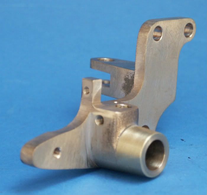
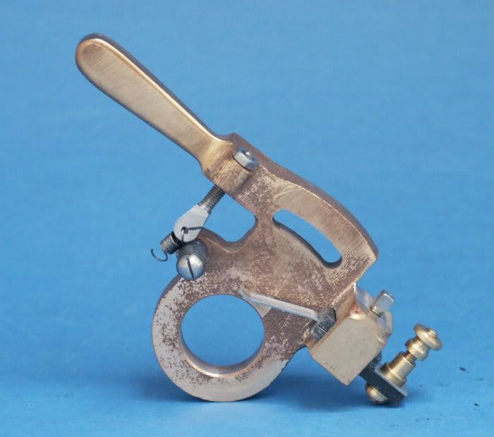
The remaining parts are mostly straight forward turning if a little bit on the small side, the main thing to get right is the 45deg seating for the "float" which need s to be lapped in so the fuel is shut off until there is a vacuum in the intake at which point the float lifts against a small spring and allows fuel to flow.

PICT03562.jpg


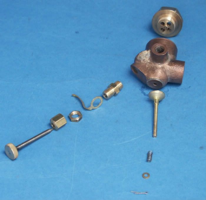
And this is how it all goes together.

PICT03552.jpg


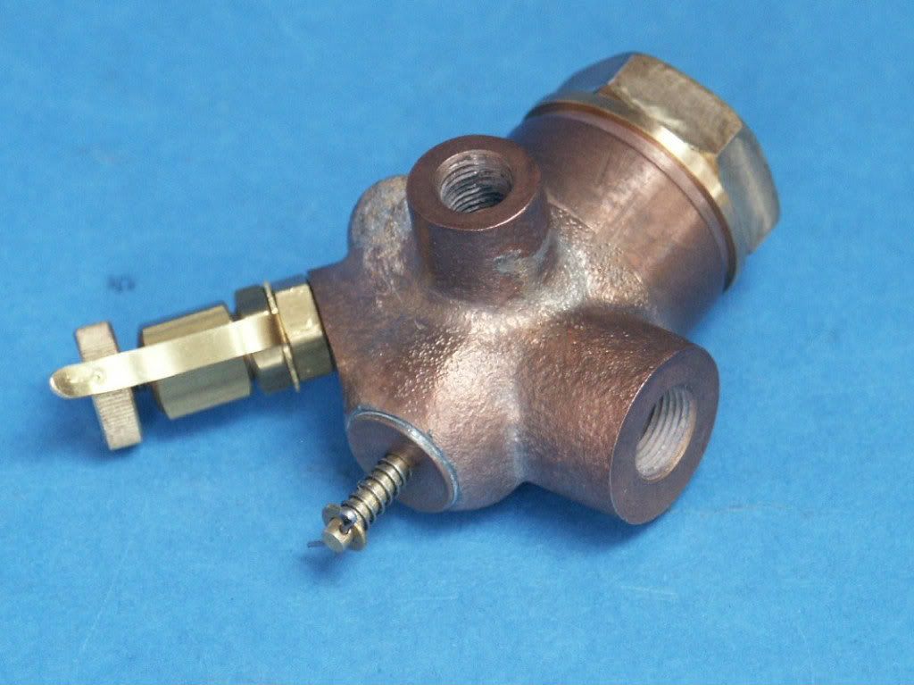
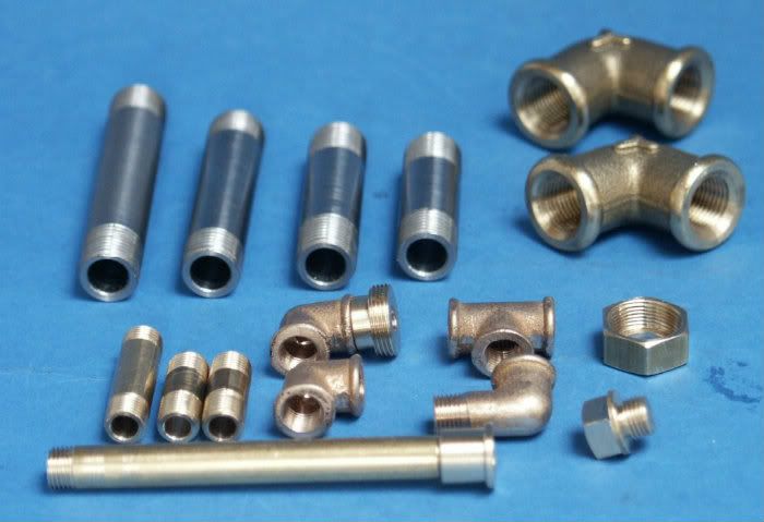
It was then just a case of making up the fuel lines, intake pipework and fuel filler pipe & cap.

PICT03542.jpg


J
 
Hi Jason

It's nice to see some more progress in your engine build. As always will be following along.

Vince
 
Wow, that looks great.

About the rings, you just used the snips to "Crack" them? I would have never guessed they would break so cleanly like that!
 
The exhaust valve and timing are actuated by a gear driven rod that passes down the side of the engine. I used a length of 1/2" presision ground mild steel for this, the gear is supplied in the kit and the rest of the parts are basic turning and milling - from left to right.

Exhaust cam
Timing collar
Corian Insulator
Bracket
Gear
Key
Cap
Cap retaining bolt

PICT03512.jpg


The other end of the rod is supported by a bracket that bolts to the cylinder head. There are 4 holes that lie on the same centreline, the best I could get was the three small ones in line and the large bearing hole slightly off.

IMAG0349.jpg


This would have been OK after cleanup had there not been about 1/16 of shift between the two halves of the casting, you can see the step on the left of the photo

IMAG0351.jpg


Which resulted in the hole on the other side being a bit off!!

IMAG0352.jpg


I got round this by mounting the casting on a mandrel, turning down the boss and then loctiting a brass sleeve in place, once painted it won't show.

PICT03492.jpg


PICT0348.jpg


The timing can be advanced and retarded by a lever that is another bronze casting, this was a bit of a pig to hold, first thing was to get a flat face

IMAG0360.jpg


I could then get it on the rotary table to bore the holes and cut the curved slot.

IMAG0361.jpg


Final job was machining a recess on the back

IMAG0363.jpg


And thats the leaver finished with a few of the fittings, the contact at the bottom is held in two bits of corian to insulate it from the engine and this makes contact with the timing collar to fire the sparkplug. The spring pulls the governor trip off the catch

PICT03502.jpg


The last of the bronze castings is the exhaust rocker, no machining pics of this just the finished item.

PICT03522.jpg


One other item that fits onto the bracket is the governor trip this is fabricated from drill rod and ground flat stock as is the catch.

PICT03532.jpg


Jason
 
And another avid follower here. Looking great Jason:)
 
Ha! The sun came up again. Great progress Jason and I love your photos.
 
Nice work Jason; thanks for the update.

Dave
 
Awesome work, love the rework of the casting.
 
The sheet metal water jacket is held on by an arrangement ofrods and brackets, these four brackets are supplied as a single casting and ittook some time to get my head around what was shown on the drawing and the lump of bronze in my hand as they are all the same but different if you know what Imean!

First job was to tidy up the casting and machine a few of the straight lines

IMAG0330.jpg


With some edges established the 3/16” holes were drilled and then the waste cut away, here are the parts along with the stainless steel rods

IMAG0331.jpg


It was then a case of rounding over one set of ends

IMAG0332.jpg


Followed by the others

IMAG0334.jpg


A final bit of hand work had them all looking nice and readyfor a trial fit

PICT0352.jpg


The actual jacket is supplied ready cut and folded so it wasjust a case of drilling and forming the rivits and then shaping round asuitable former to get it round

PICT0361.jpg


There are two drip feed oilers, one for the piston and onefor the crank, therse followed drawing except I went for 1/8” smaller diameterglass tube.

PICT0358.jpg


J
 
Hi Maestro,

I am following your engine build. Picking up new knowledge and hopefully new skills to go on to tougher jobs. This is one engine I can only see and cannot build in my balcony machineshop.:wall:

However the least I can do is the Drip Feed Oiler. Grew up with this in Metal Box/Continental Can. Please email drawing. Drip Feed Oilers are not extinct in Singapore.
 
Last edited:
Gus

You can get drawings for Lunkenheimer style oilers in 1/4 scale from Morrison & Marvin. They include some of the small bits with the drawings. USD10.00 including international shipping.

Have a look at http://www.morrisonandmarvin.com/order.php

Dave
The Emerald Isle


Hi Dave,
Thanks.Went in and bought one pce for my antique collection. Oilers are extinct in Singapore. First saw this as a young lad on a overhead pulley drive "Shanghai" Lathe.
 
Gus

The machining notes included are quite useful, especially for the not so gifted machinists like me.

Once you have the drawings, you can scale them up for a larger engine if you want. If no real glass the right diameter is available, you can use plastic tube or even drill out a solid piece of plastic. The other bits are quite easy to make in the larger sizes.

Dave
The Emerald Isle
 
I built the same engine several years ago, I made a cylindrical tube stuffed with steel-wool and "engine-turned" the outside surface of the copper water jacket and the horizontal shaft for the cam. It makes a really nice addition to an otherwise blank surface. This may be the best running engine I've completed.
 
Last edited:
Back
Top