Half Scale Domestic "Stovepipe" build

Home Model Engine Machinist Forum

Help Support Home Model Engine Machinist Forum:

This site may earn a commission from merchant affiliate links, including eBay, Amazon, and others.

Very nice work, as usual Jason.

That's a pretty serious crank you made there. :eek: Nicely done.
 
Jason excellent work as usual and making progress. I am still here interested and love your documentation to details.

Don
 
Keep up the good work Jason, still watching with great interest.

Peter
 
Every new part is looking just great Jason...I am really enjoying both your build and the excellent documentation, not to mention looking forward to your next update. Nice job on the flywheels and muffler and that crank too !!!

Bill

 
Thanks for all the comments, cylinder head next, hope you are sitting comfortably its a long one.

The kit is supplied with some photos and accompanying notes on various machining setups. It shows the first thing to be dome on the head as machining the base, unfortunately the set up shown would need a 10-12” 4 –jaw to have long enough jaws and even then is a bit iffy as you can only hold about 1/16” of the cast rim!!

I opted to set the head up on the mill with shims to ensure the cast external face was as true as possible. I then reduced the valve stems to height, these were chilled and it blunted a ½” mill with the first touch so changed to a little hogger to finish them off. At the same time the three head mounting holes were drilled ¼”and accurately spot faced to the same height.
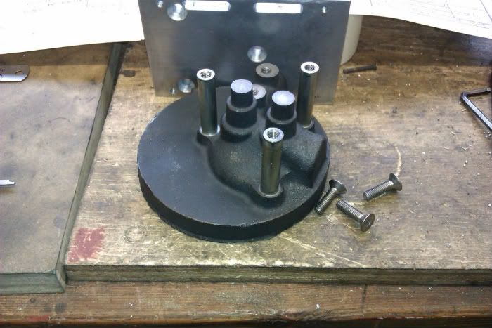
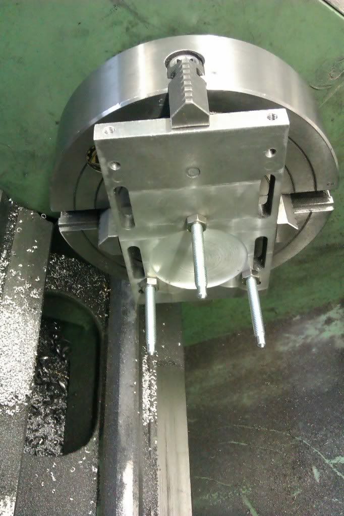
IMAG0293.jpg


I took advantage of the ¼” holes and tapped them part way with a 9/32x40 tap and machined up some posts to screw into these.

IMAG0313.jpg


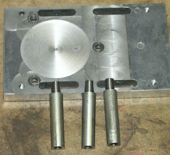
The other ends of the posts were tapped M6 to take CSK screws and an alloy plate drilled and CSK to the same bolt pattern as the head.

PICT0337.jpg


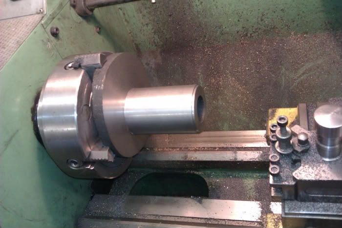
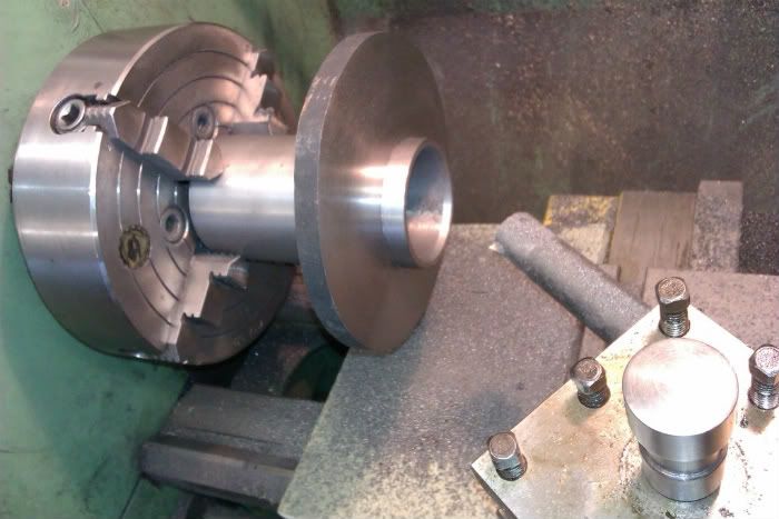
Without disturbing the plate after drilling the head was screwed on, a skim cut taken across the top and the centre point spotted.

IMAG0312.jpg


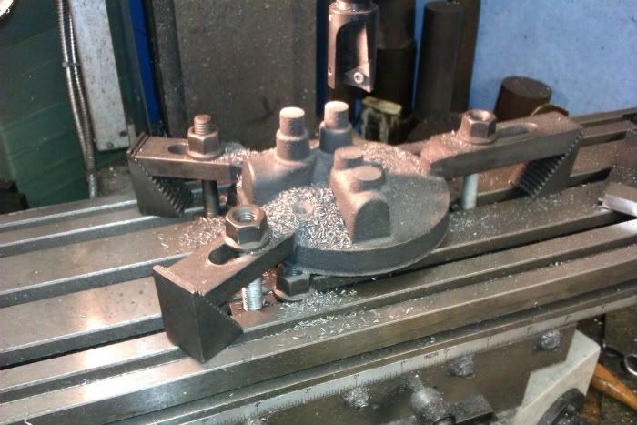
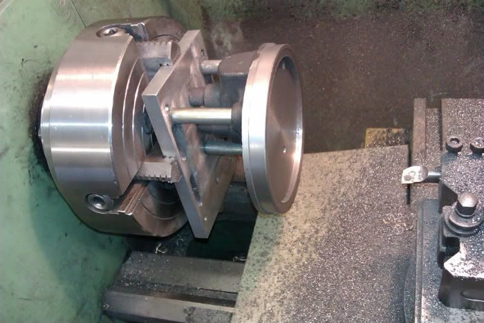
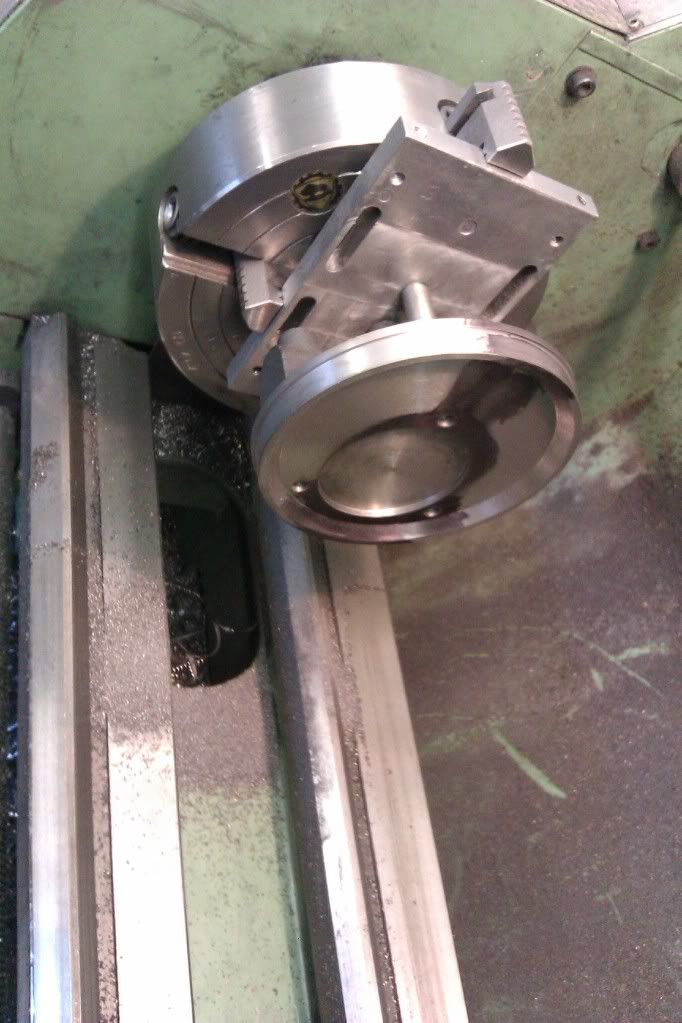
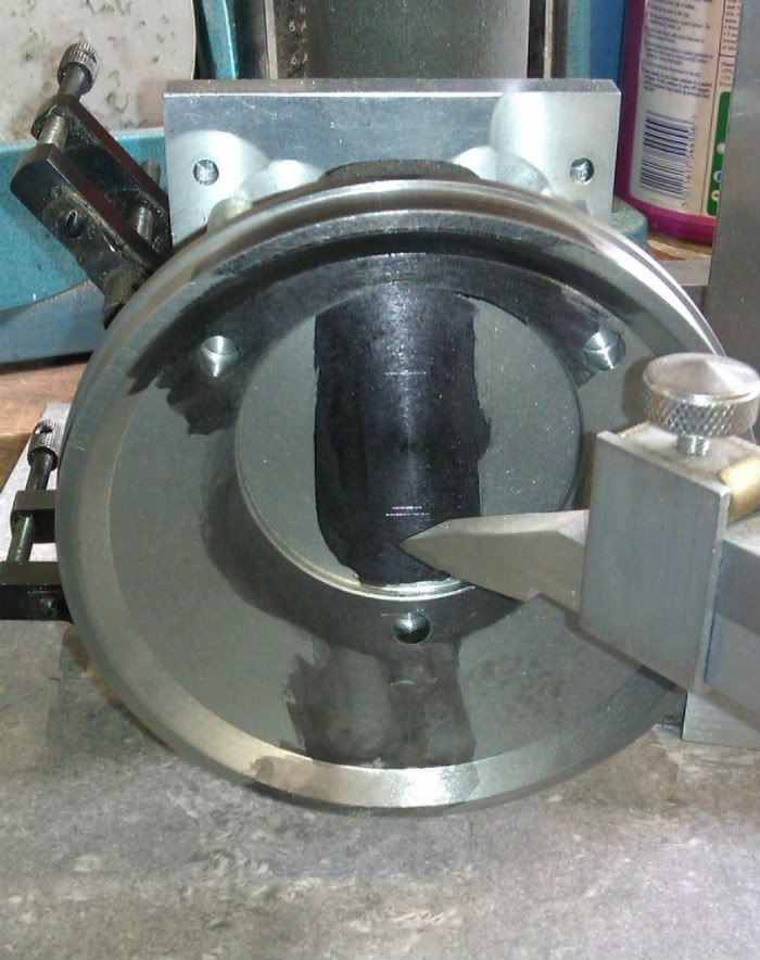
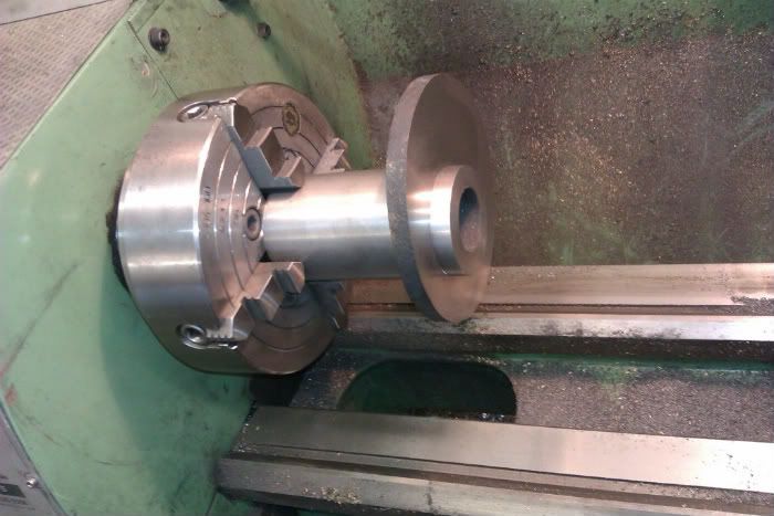
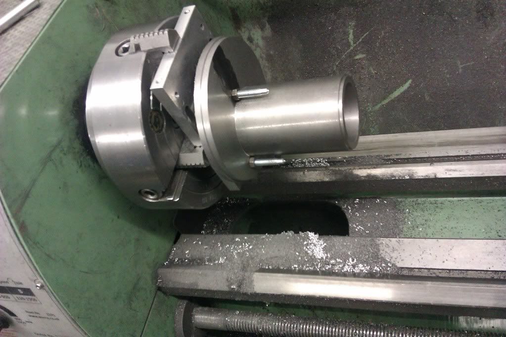
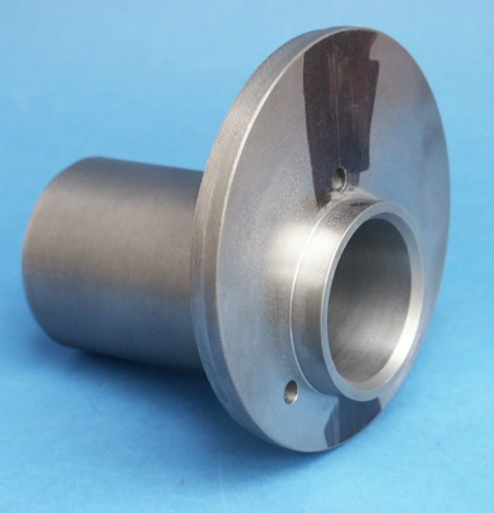
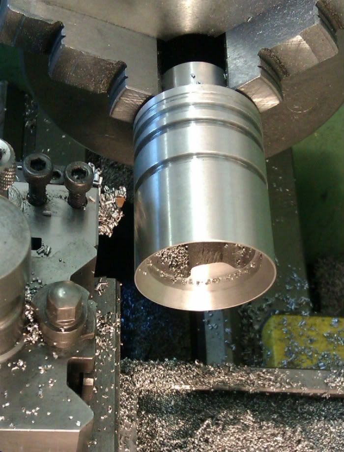
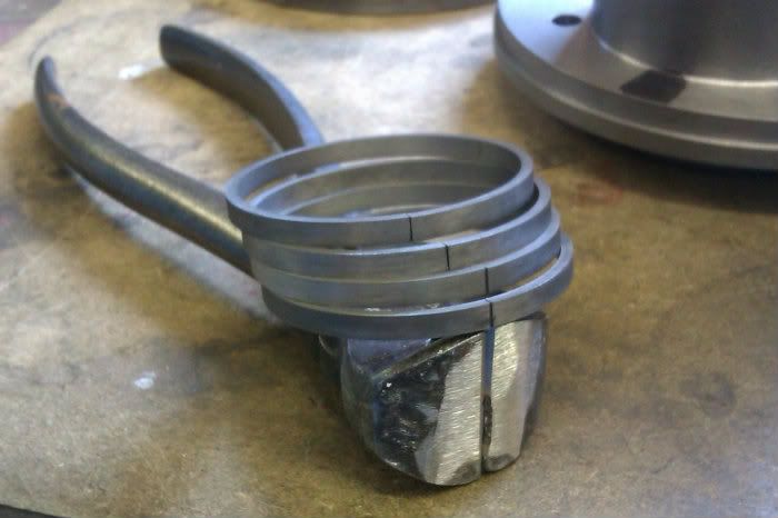
The whole thing was then set up in the 4 jaw and the spotted centre set to run true after which the casting was machined back to thickness and recessed out. The outside was also trued up and the step for the wrapper cut.

IMAG0314.jpg


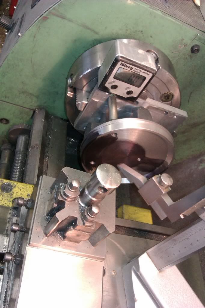
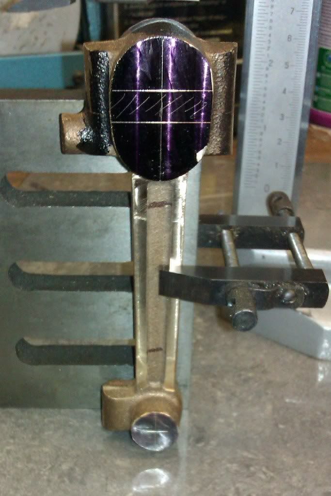
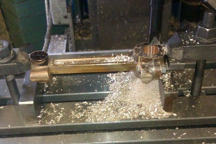
I now had to machine another eccentric recess to take the end of the cylinder. A digital angle block was zeroed and a height gauge used to mark centre height, the gauge was then adjusted to the correct offset, work rotated 90degrees and the work marked

IMAG0316.jpg


IMAG0317.jpg


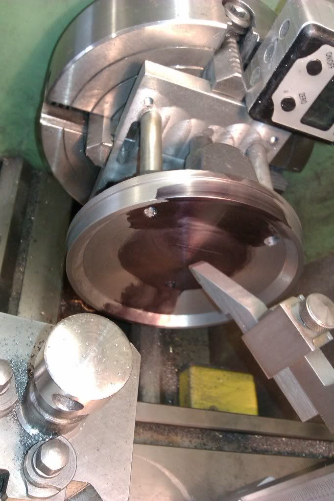
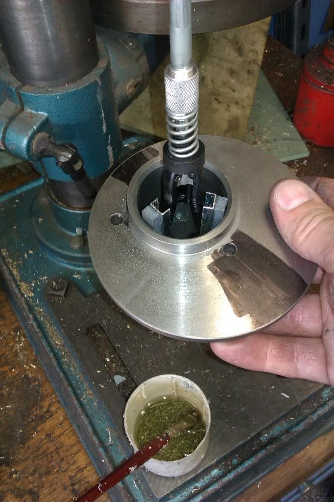
The intersection of the two lines was marked using an optical centre punch and this was then clocked true in the 4-jaw and the recess cut.

IMAG0318.jpg


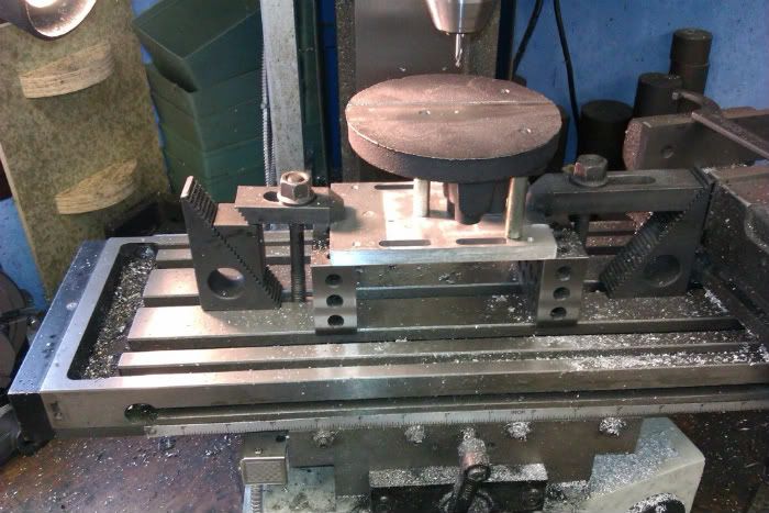
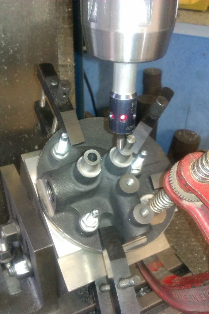
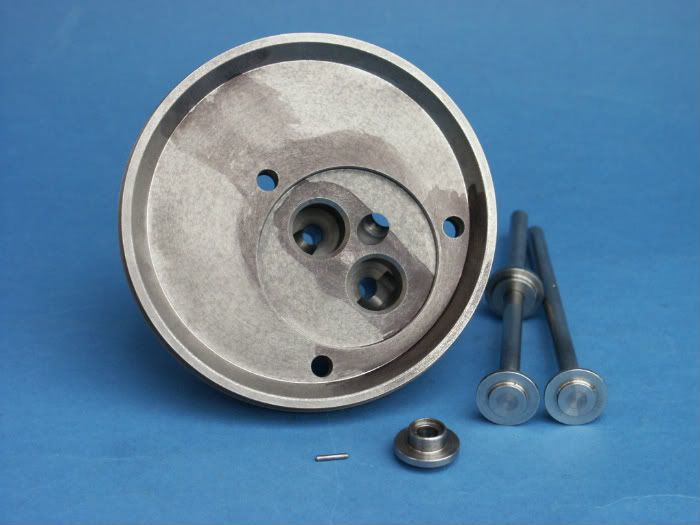
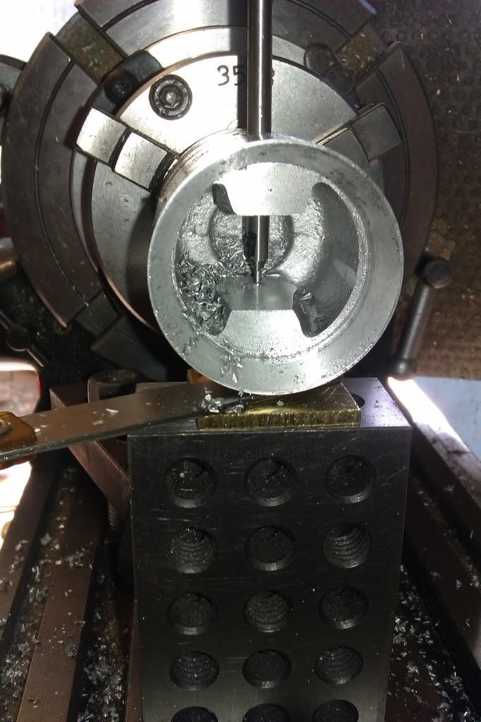
The head and machining plate were then transferred to the marking plate for the position of the two valves to be established.

IMAG0344.jpg


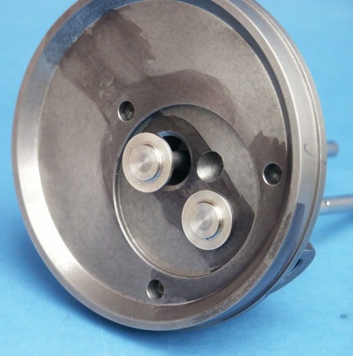
These were then drilled, counter bored and the valve seats machined ay 41degrees. I had previously fabricated and part machined the valves so these could have their sealing faces machined straight afterwards without altering the top slide angle.

IMAG0346.jpg


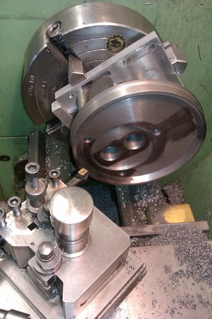
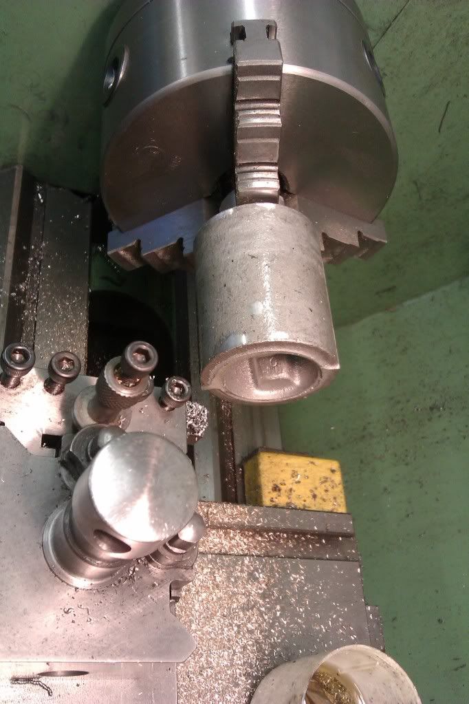
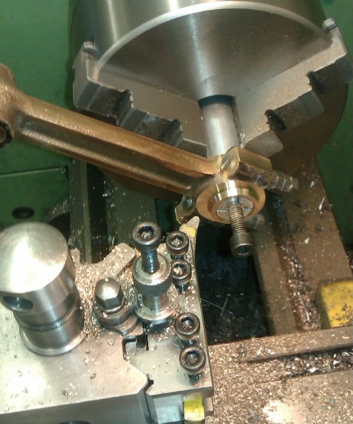
As you can see things were getting a bit eccentric by now so speed had to be kept down and care taken to manually rotate the check before any machining started to ensure the eccentric part would not hit anything before switching on.

[ame]http://www.youtube.com/watch?v=m-_PQnPYdgs[/ame]

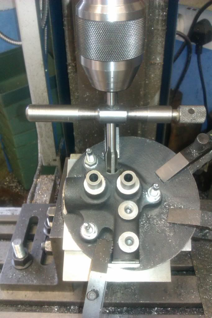
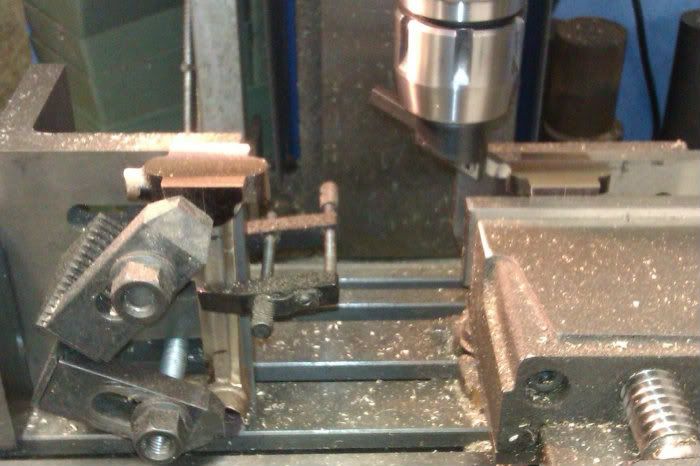
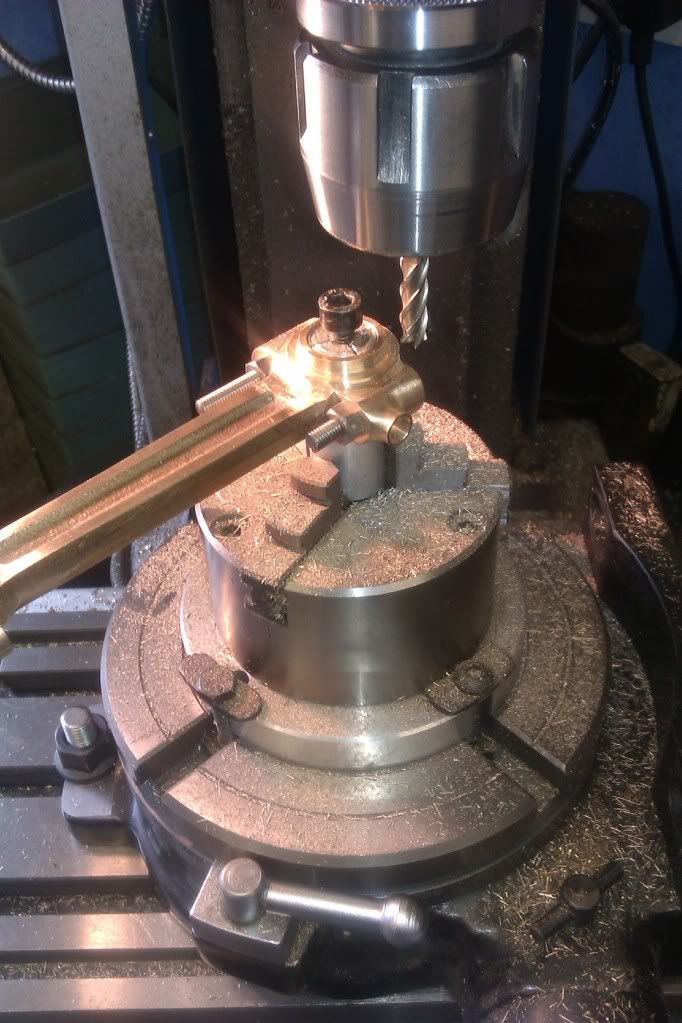
With all the turning done the head was mounted on a pair of angle plates set to the required 30degrees for the sparkplug hole. I used a bit of silver steel (drill rod) in the valve guides to touch the edge finder against to set the hole central to the two valves.

IMAG0347.jpg


The hole was then tapped M10x1 using a small centre in the chuck to keep the tap in line and finally the hole was spot faced.

IMAG0348.jpg


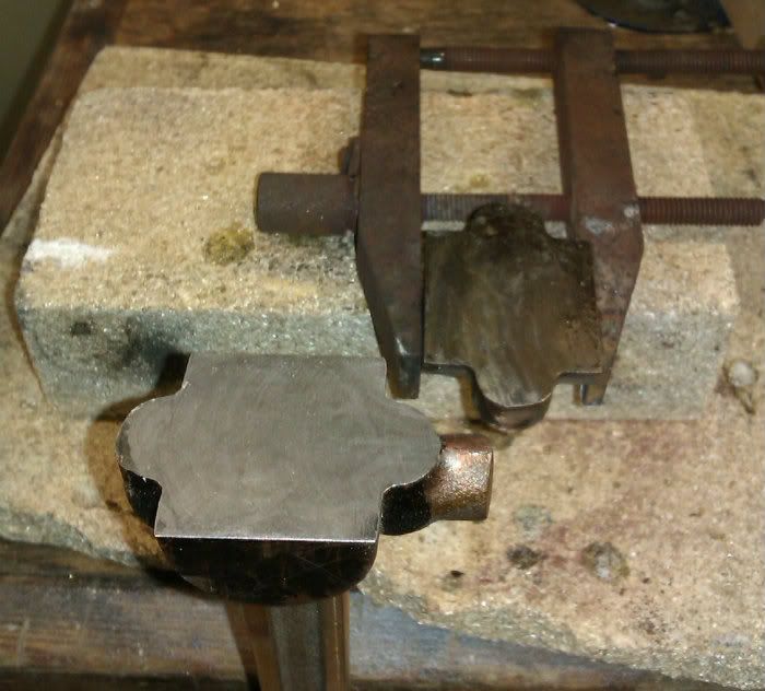
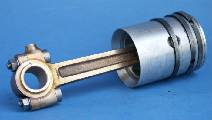
All that was left was to face, drill and tap the inlet & exhaust and that was the head finished (valves are overlong at the moment to give something to hold while grinding in)

PICT0343.jpg


PICT0344.jpg


PICT0345.jpg


Jason


Thats a real beutiful peice of work Jason well thought out and shown

:bow: :bow: :bow:

Stew
 
Gee! Jason you make that all look so easy. That is some great setup, I especially like the way you put your digital angle gauge on the lathe and clocked your angle. The setup up plate pure genius. I wish I could be right there with you when you are doing the actual setups. This is pretty close too but not the same. Keep your documentation to details coming, I love it.

Don
 
I finished mine several years ago, I wish I'd been able to see your approach to some of these operations, but that's what makes this hobby so interesting. There are "Lots of ways to skin a cat". This is one of the strongest running engines I've built. When it comes to the cam, I ended up building up a lump of Bondo on the first unsuccessful attempt and shaping my own lobe, once trial & error produced a good profile, I replicated it in steel.
 
Philip, thanks for the tip about the cam, I'll see how it runs and take it from there. Saw the photos of your engine and you have done a nice job of it though the engine turning is not my cup of tea.

Well back to the build, with the cylinder head done the next obvious part was the cylinder. This is quite a large casting with an offset flange to form one end of the water jacket. I started buy holding it by this flange and turned the OD and inside face of the flange.

IMAG0289.jpg


I then reversed it in the chuck, clocked it all true and then faced the flange back to thickness, formed the spigot that fits into the crankcase and then bored to 1.749”

IMAG0290.jpg


The final job while in the chuck was to put a taper onto the end of the bore to help with getting the piston rings into the cylinder. You may notice that for the boring I switched to the old 4 way toolpost that came with the lathe as this allows me to hold a thicker boring bar than the QCTP.

IMAG0292.jpg


The machining plate that I used for the head was again put into use, I cut a shallow recess for the spigot to locate into and fitted some longer screws.

IMAG0319.jpg


This allowed me to hold the casting so that the flange ran true and the edge was reduced to the required dia and a step machined for the water jacket wrapper.

IMAG0320.jpg


The final job was to hone the bore with a brake cylinder hone, I did this with the hone in the pillar drill at its slowest speed and just held the casting by hand and gently worked it up & down.

IMAG0342.jpg


This is the finished item

PICT0346.jpg


The cast ali piston comes with a good sized machining spigot, the casting was trued up in the 4-jaw and the spigot skimmed, I then reversed the casting round held buy the spigot.

IMAG0336.jpg


It was then just a case of turning, boring the skirt and cutting the piston ring grooves.

IMAG0339.jpg


I then moved over to the mill and held the piston in a 3-jaw mounted on the rotary table and milled the inside faces to width for the conrod little end, without altering the R/T it was then mounted vertically to drill and ream for the gudgen pin(wrist pin), to ensure the drill started true on the second part of the cut I used a long series centre drill to get it started. Note the packing under the piston to stop any chance of it deflecting down as the 3/8” hole was formed.

IMAG0341.jpg


It was then back to the lathe to face off the top and form the shallow recess. This is it with the wrist pin and screws used to stop the pin rotating, and the next is it all assembled.

PICT0349.jpg


PICT0350.jpg


And to round off a couple of shots of the current state of progress as described so far.

PICT0354.jpg


PICT0355.jpg


J
 
That's looking really good Jason Thm:

Kind regards, Arnold
 
Welcome back Jason glad to see you have made progress. It is really looking great to me and as usual you documention and photos are superb.

Thanks Don
 
Great update Jason; the Domestic is coming along nicely.

Thanks for posting your progress.

Dave

 
Jason
I wanted to say thank you for documenting your progress so well - you do great looking work! After reading your crankshaft turning post it inspired me to build my F/M 25 hp crank the same way and it worked out great! I will be following the rest of the build.
Thanks again,
Brad
 
Good to hear it was of help Brad.

I must catch up with tehe build descriptions as the engine is almost finished :) infact I fitted the valve springs the other day and on turning the engine over thought something had jammed, it was just the compression ;D

J
 
Nicely done Jason! Love to see some more pictures!

Dave

 
Always look forward to more updates on this one Jason...such a nice engine and great progress so far.

Bill
 
th_wwp

Yea you have probably seen that one before ;D

But some progress photos would be nice; I really enjoyed the Famous build so the precedent has been set.


Dave
 
Hi Jason,

This engine is going to be beautiful, More pictures please.

Regards Gary
 
Well I had to look back to see where I left off as it's been a while since I posted any progress but it looks like I left off with the piston so the next parts I must have made were the piston rings.

These were turned from CI bar, parted off and then split with the cutters you can see in the photo before being spread open and heated to red heat for a few mins.

IMAG0423.jpg


Next up was the bronze conrod, the drawings have a note to make this a little shorter to reduce compression so the hole does not fall ideally in the middle of the boss which means a bit more clean-up work but nothing too difficult. First I took a light skim off each side to give a ref face and something decent to mark out on.

IMAG0367.jpg


The casting was then sawn in half with a hacksaw and the two mating faces flycut back to the lines

IMAG0370.jpg


The two faces were then tinned with plumbers soft solder and then sweated together, this way there is no risk of the parts moving while drilling for bolts and machining.

IMAG0372.jpg


I set the rod up on packing and bored the big end, followed by the small

IMAG0373.jpg


The holes for the fitted bolts were reamed and flats machined each end, with the added security of the bolts the rod was mounted onto an expanding mandrel and the sides finish turned.

IMAG0374.jpg


It was then just a case of several milling opperations to get the big end in particular to the correct shape.

IMAG0382.jpg


And here it is fitted to the piston.

PICT03472.jpg


J
 
Back
Top