arnoldb
Well-Known Member
- Joined
- Apr 8, 2009
- Messages
- 1,792
- Reaction score
- 12
I've been spending a lot of shop time on experimental work, and reached a point where I first need to build a bending roll to continue - GH Thomas's design is perfect for my needs. Checking my stock inventory this morning, I could not find some of the material I thought I had...
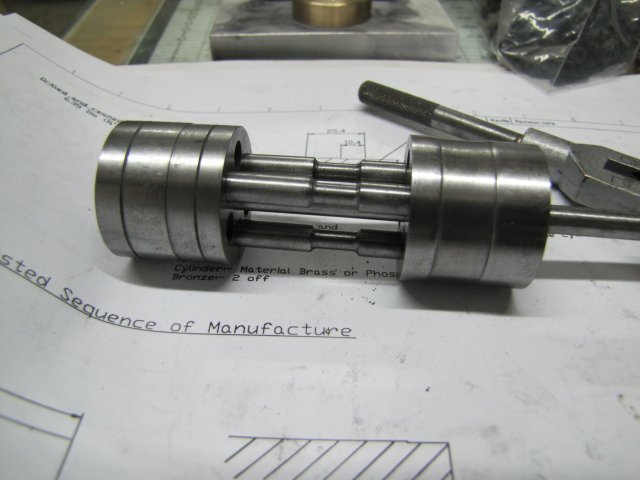
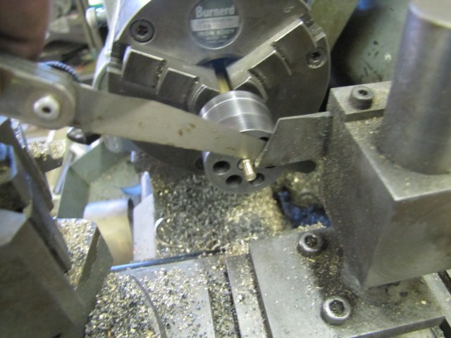
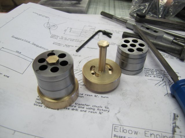
I've not built an engine for a while, so decided to divert from my experiments and the bending roll for a while and build an engine. I've had my eye on the elbow engine for quite a while, so I decided now's the time. I think I can keep to the required accuracy, and there's some great tips here on HMEM from Bogs, Stew, Rick and others on getting the thing going; it is by all accounts a finicky, difficult and frustrating engine to get to run, but I'm up for the challenge.
I'm working from Stew's plans - He incorporated a lot of nice features, and the plans are in metric, saving me some calculations")
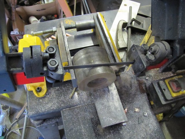
Scratching around for stock, I found this lot:
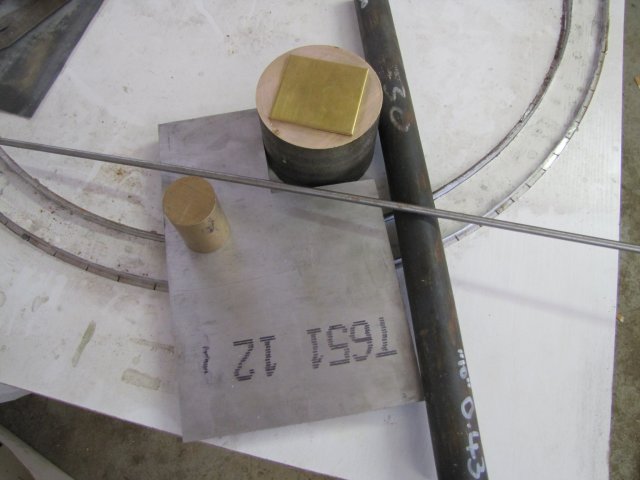
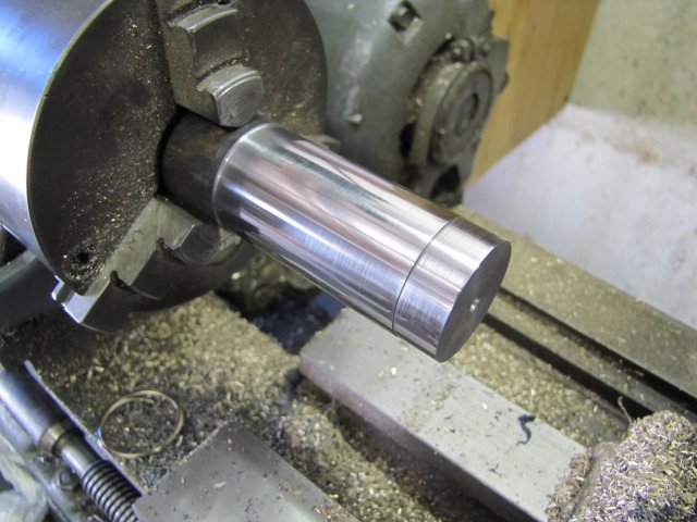
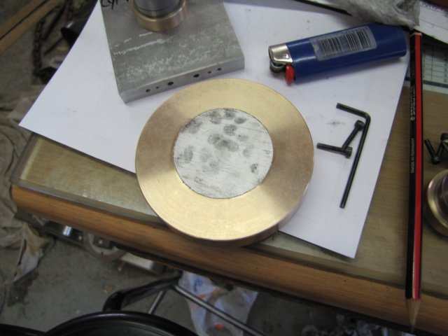
12mm aluminium plate for the base and flywheel post, 100mm bronze with a hole through it hidden by the 4mm brass plate I'll use to make a built-up flywheel, a bit of 35mm brass rod to make the valve ports from, some 30mm cast iron to make the cylinders from - I dont have brass for this, but the CI should be OK as the coefficient of friction with steel when moving and lubricated is pretty much the same as that of brass to steel, and some 6mm silver steel to make the pistons from.
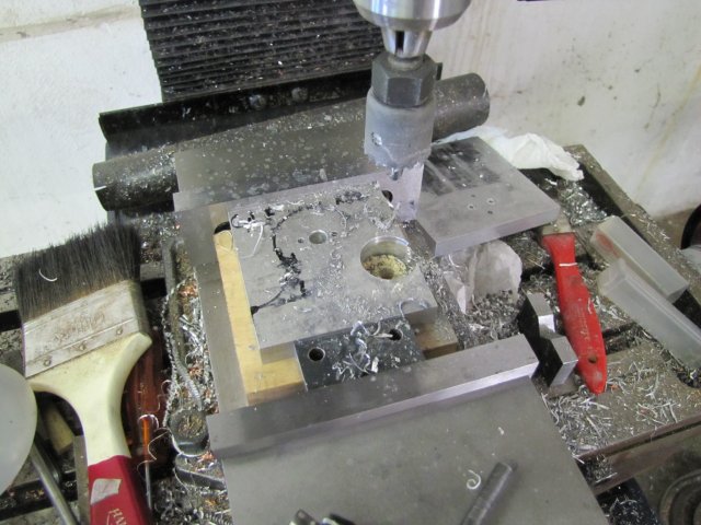
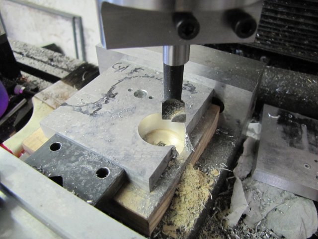
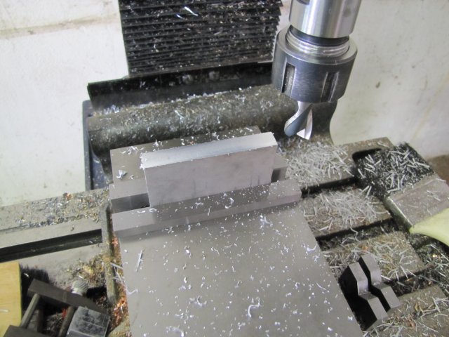
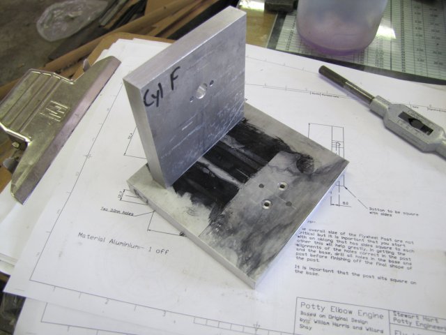
The base and flywheel post was roughly band-sawn from the bit of plate, then I started cleaning up the edges. Here I've finished getting the base square and to size; a block of wood serves as a parallel to lift the workpiece far enough in the mill vise for the chuck to clear, and a toolmaker's clamp with a bit of scrap as a vise stop:

The flywheel post needs to have its base perfectly - as near as perfect as one can get it - square, so I milled it standing upright in the vise. A good angle plate would be a boon here, but I used what I have, and my vise is pretty square:
I _could_ have turned up a couple of cylindrical squares to substitute for an angle plate, but that's an exercise for another day
A check with my "best" machinist square, and things look good to go:
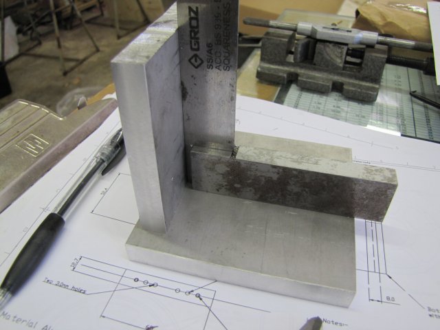
??? I wonder if I can remove the rust from it and still maintain a semblance of accuracy on it ?
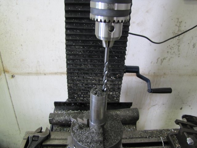
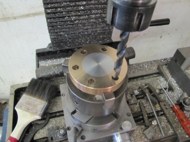
Next up was an exercise in mill-dial calculations, x handwheel spinning and deep-hole-drilling in aluminium... I don't have long series drills, and this project really requires it, so I had to go for some carefully thought out modifications bodges. Fortunately there is a load of room between the needed holes, so going for bigger drills for the deep holes is not a problem. For the flywheel column, I went for a 4mm drill instead of the 3mm required. Here you can see the two together; the 3mm drill pushed against the chuck jaws, the silver mark on the 4mm showing the depth I drilled to (just above my thumb), and there is just 5mm of that 4mm drill chucked up:
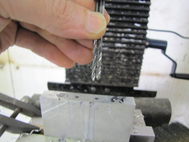
It is not ideal to chuck such a short bit of a drill, and will cause chuck damage. I first chucked the drill bit normally, and drilled as deep as I could get; lot's of cutting fluid (methylated spirits for me in ali), peck-drill 2-3mm at a time till the chuck jaws are close to the workpiece, then extend the drill a bit & repeat.
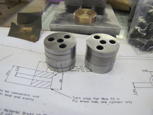
The deep port holes in the base, the best I could come up with was drilling with a 6.8mm drill... There's barely enough space, but it will do:
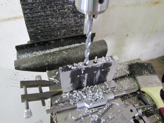
That drill bit is actually black; the gray on it is from the deep drilling. Why 6.8 ? - well, it reaches far enough, and I can tap the port ends for M8 for the steam/air connectors
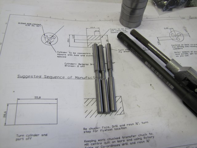
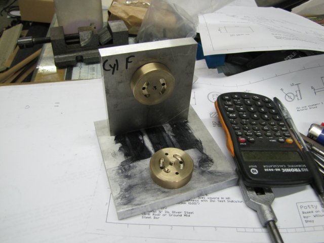
The lot assembled so far; everything aligns very well ;D - even if it looks crude so far. The counter bores on the base are 0.8mm deep, to take 4mm ID x 1mm thick O-rings and allow for compression; I had to change Stew's dimensions a bit there as that is what I have.
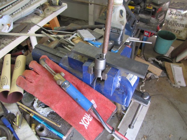
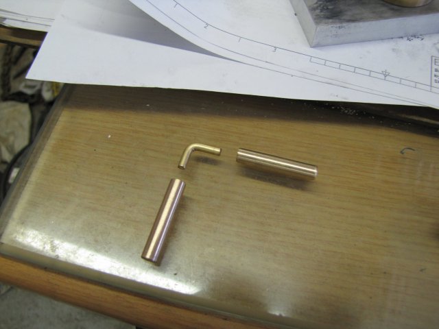
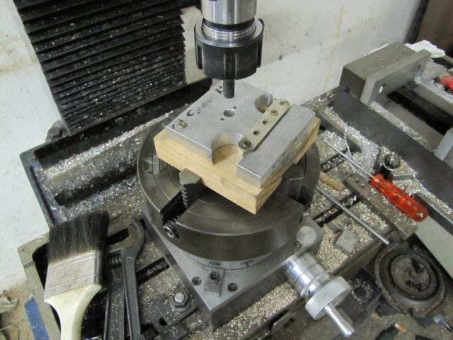
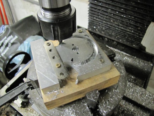
Next up - after a diversion to my day-job office to attend to some servers, the alarm system, and taking some photos for the company's web-site-under-development - work on the valve ports. This is the bottom one partly done:
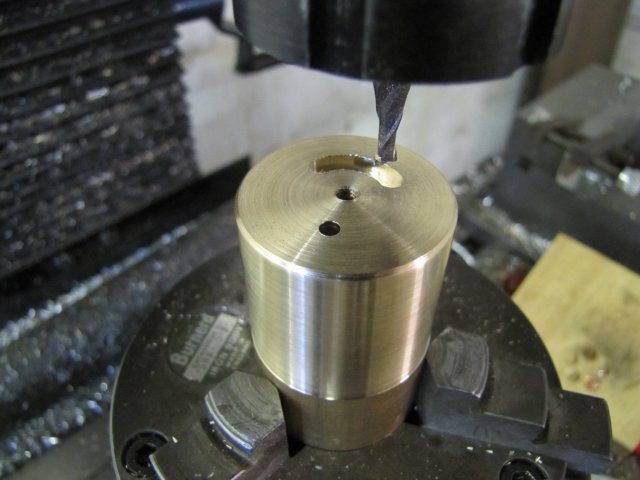
I don't have a 5mm slot mill, so I used a 4mm one for this; if needed, I might have to increase the rotary angles of the milled ports later - as using the smaller milling bit leaves them "shorter" in circumference than designed, but that is better than having them too long, as there is a point at which the milled slots would connect incoming steam/air directly to the exhaust if overdone. IMO the bits between is basically a top/bottom "deadish" bit, where the addition of steam/air, or the resistance to exhaust does not have too much of an affect.
The flywheel valve port needs a close-fitting "stem" to fit in its column. My parting tool is thinner than any of the measuring calipers I have, so getting it to size puzzled me a bit... Measuring in the parting slot was a challenge - none of my digital or dial calipers fit in there :, and then I remembered my little-used little OD spring calipers. Works a treat ;D - With the lathe STOPPED!:
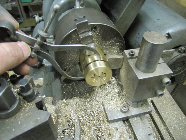
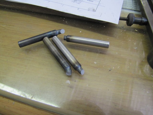
I stopped work today with the base, flywheel post, and both valve ports done:
There is one glitch though... Stew's plans show the M3 tapped mounting holes for the base valve port from the top. They should be from the bottom. Working from the plans, I fell in this hole - literally :big:. To recover, I had to drill and tap the holes right through the valve port instead of having blind holes. If needed, I'll make a couple of threaded plugs to seal the holes on the cylinder side of the port, but that might not be necessary.
Regards, Arnold
I've not built an engine for a while, so decided to divert from my experiments and the bending roll for a while and build an engine. I've had my eye on the elbow engine for quite a while, so I decided now's the time. I think I can keep to the required accuracy, and there's some great tips here on HMEM from Bogs, Stew, Rick and others on getting the thing going; it is by all accounts a finicky, difficult and frustrating engine to get to run, but I'm up for the challenge.
I'm working from Stew's plans - He incorporated a lot of nice features, and the plans are in metric, saving me some calculations
Scratching around for stock, I found this lot:
12mm aluminium plate for the base and flywheel post, 100mm bronze with a hole through it hidden by the 4mm brass plate I'll use to make a built-up flywheel, a bit of 35mm brass rod to make the valve ports from, some 30mm cast iron to make the cylinders from - I dont have brass for this, but the CI should be OK as the coefficient of friction with steel when moving and lubricated is pretty much the same as that of brass to steel, and some 6mm silver steel to make the pistons from.
The base and flywheel post was roughly band-sawn from the bit of plate, then I started cleaning up the edges. Here I've finished getting the base square and to size; a block of wood serves as a parallel to lift the workpiece far enough in the mill vise for the chuck to clear, and a toolmaker's clamp with a bit of scrap as a vise stop:
The flywheel post needs to have its base perfectly - as near as perfect as one can get it - square, so I milled it standing upright in the vise. A good angle plate would be a boon here, but I used what I have, and my vise is pretty square:
I _could_ have turned up a couple of cylindrical squares to substitute for an angle plate, but that's an exercise for another day
A check with my "best" machinist square, and things look good to go:
??? I wonder if I can remove the rust from it and still maintain a semblance of accuracy on it ?
Next up was an exercise in mill-dial calculations, x handwheel spinning and deep-hole-drilling in aluminium... I don't have long series drills, and this project really requires it, so I had to go for some carefully thought out modifications bodges. Fortunately there is a load of room between the needed holes, so going for bigger drills for the deep holes is not a problem. For the flywheel column, I went for a 4mm drill instead of the 3mm required. Here you can see the two together; the 3mm drill pushed against the chuck jaws, the silver mark on the 4mm showing the depth I drilled to (just above my thumb), and there is just 5mm of that 4mm drill chucked up:
It is not ideal to chuck such a short bit of a drill, and will cause chuck damage. I first chucked the drill bit normally, and drilled as deep as I could get; lot's of cutting fluid (methylated spirits for me in ali), peck-drill 2-3mm at a time till the chuck jaws are close to the workpiece, then extend the drill a bit & repeat.
The deep port holes in the base, the best I could come up with was drilling with a 6.8mm drill... There's barely enough space, but it will do:
That drill bit is actually black; the gray on it is from the deep drilling. Why 6.8 ? - well, it reaches far enough, and I can tap the port ends for M8 for the steam/air connectors
The lot assembled so far; everything aligns very well ;D - even if it looks crude so far. The counter bores on the base are 0.8mm deep, to take 4mm ID x 1mm thick O-rings and allow for compression; I had to change Stew's dimensions a bit there as that is what I have.
Next up - after a diversion to my day-job office to attend to some servers, the alarm system, and taking some photos for the company's web-site-under-development - work on the valve ports. This is the bottom one partly done:
I don't have a 5mm slot mill, so I used a 4mm one for this; if needed, I might have to increase the rotary angles of the milled ports later - as using the smaller milling bit leaves them "shorter" in circumference than designed, but that is better than having them too long, as there is a point at which the milled slots would connect incoming steam/air directly to the exhaust if overdone. IMO the bits between is basically a top/bottom "deadish" bit, where the addition of steam/air, or the resistance to exhaust does not have too much of an affect.
The flywheel valve port needs a close-fitting "stem" to fit in its column. My parting tool is thinner than any of the measuring calipers I have, so getting it to size puzzled me a bit... Measuring in the parting slot was a challenge - none of my digital or dial calipers fit in there :
, and then I remembered my little-used little OD spring calipers. Works a treat ;D - With the lathe STOPPED!:
I stopped work today with the base, flywheel post, and both valve ports done:
There is one glitch though... Stew's plans show the M3 tapped mounting holes for the base valve port from the top. They should be from the bottom. Working from the plans, I fell in this hole - literally :big:. To recover, I had to drill and tap the holes right through the valve port instead of having blind holes. If needed, I'll make a couple of threaded plugs to seal the holes on the cylinder side of the port, but that might not be necessary.
Regards, Arnold