Gerry's Beam Engine - Metric

Home Model Engine Machinist Forum

Help Support Home Model Engine Machinist Forum:

This site may earn a commission from merchant affiliate links, including eBay, Amazon, and others.
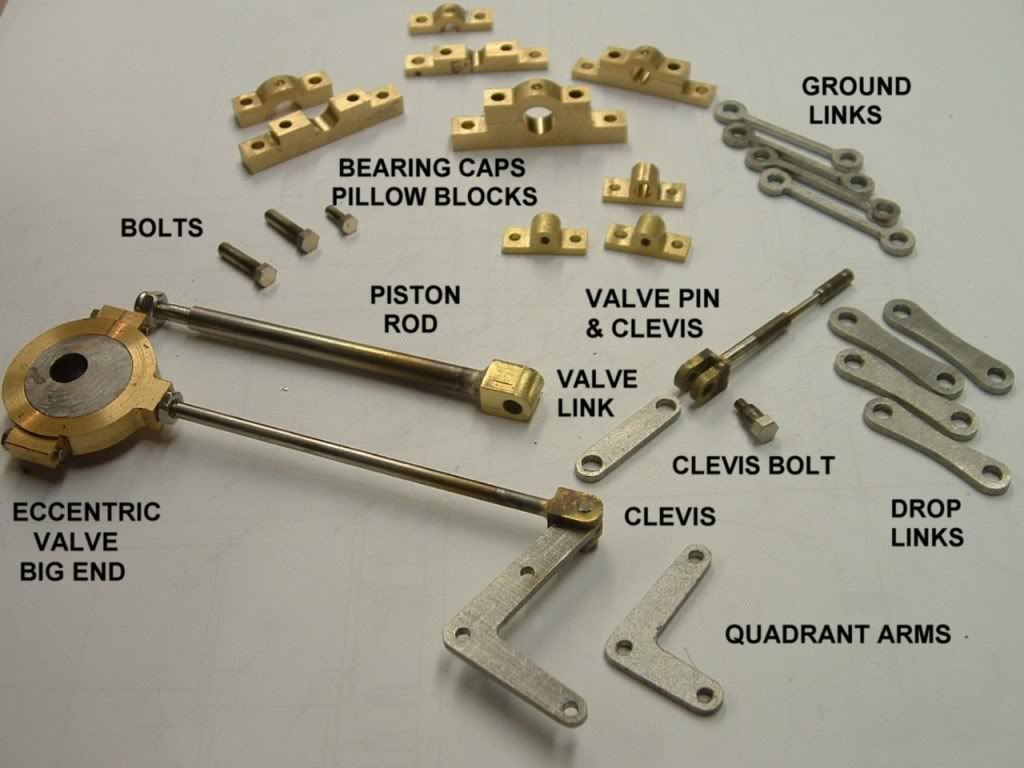
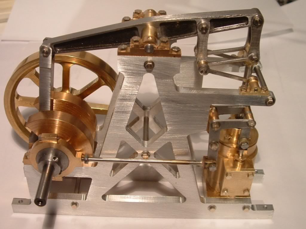
In respone to Stemo's request for a photo of any smaller parts I have made thus far...

smallparts1.jpg


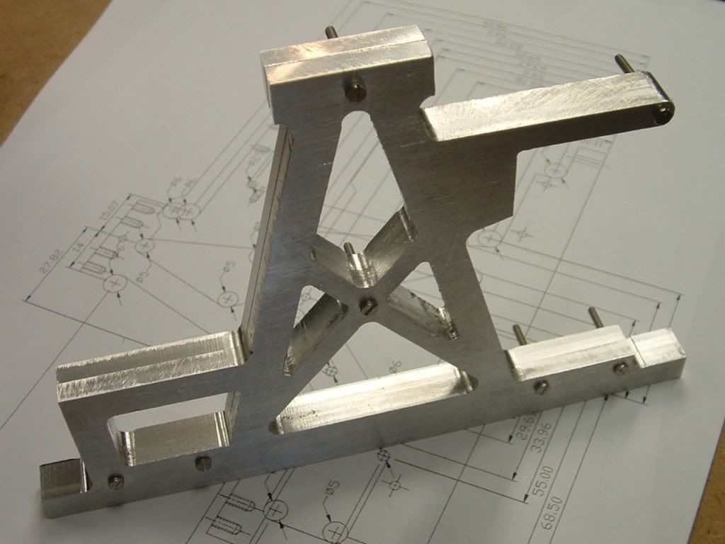
The radii on the bearing caps was cut using TC router bits normally used for woodwork.

m2bolt.jpg


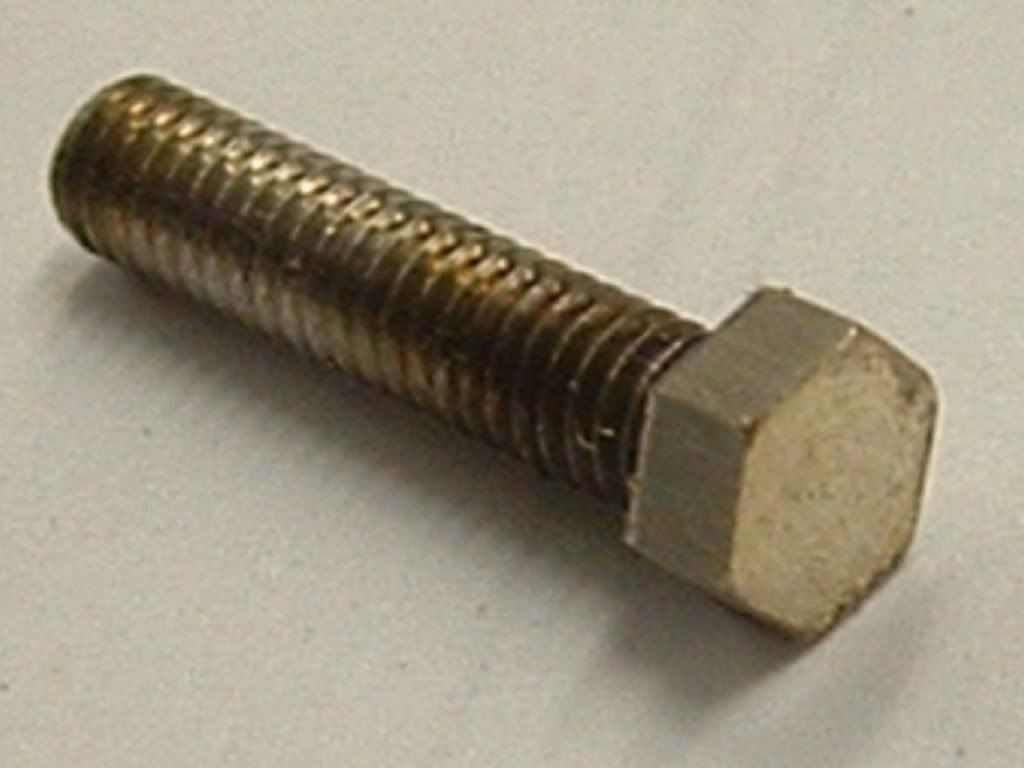
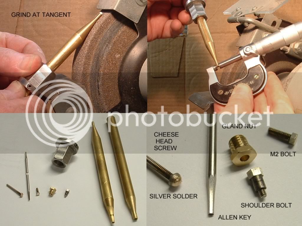
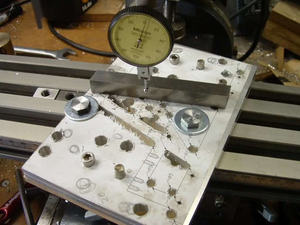
I made the small bolts by using cheesehead screws - silver soldering the slot and then grinding on the hexagon using this little fixture below.
I
Hex-Grind.jpg


Ken

 
I made the main chassis plates by printing 1=1 to my 1200 dpi printer - which I think is more accurate than I can mark out - besides I don't have a height gauge & surface table - so its way better than I can manage with a setsquare etc.

Printed onto A4 lable (self adhesive) paper.
I cut off a thin strip of the backing (release) paper along one edge - this make positioning much easier than with the whole sticky surface active - once correctly positioned - stick down the thin edge - bend over double to feed out the remainder of the backing - if you screw up (I did) start again - prints are cheap.
frame1.jpg


Since the material had been dressed to size (by my supplier, who took the sizes way too litterally) I was forced to accurately apply to an edge - I would much rather have machined the edge referenced to the holes.

Centrepunch, drill and ream all the holes - reaming for reasons of using pins to align it on my mill - note also addition of numerous holes which align with my "T" slot pitches for the various angles - starting to look like Swiss cheese.
frame2.jpg

Algin & mill.
frame3.jpg


Job done - still requires edge on drilled & tapped holes plus hand finish and black anodising.

Ken
 
Thats coming along nicely Ken.

What sort of colouring dye do you use for anodizing? - It would be nice to know what's available "locally"

Regards, Arnold
 
Thanks Arnold, you are pretty much restricted to black, bronze & clear - the more colourfull greens, reds, purples etc. are typically only available if the anodiser is doing a large customer batch - generally means a long wait. Ask your local anodiser ?

Made the flywheel - decided to use the "industrial" looking model Clampex double taper coupling to mount it.

flywheel.jpg


Changed the drawing to R2.5 in all corners - what on earth was I thinking using different rads.

Just trial fitting at this stage.

It's starting to come together.

Ken

View attachment Clampex.dwg
 
Trial assembly

Everthing fits together as planned - anyone who is working from my metric plans can breathe a sigh of relief - I was terrified I would find some obvious blunder in my redesign and have to apologise profusely.
front.jpg

There is a tight spot in the cycle - I think the problem is in the conrod big end.
No gland packing, gaskets or sealant yet - will probaly do a trial run this week.
rear.jpg

Then I've got to strip everything - do all the finishing and have the frame anodised and construct a base - I have a piece of black granite that might do the job.

I'll have a beer now.

Ken
 
Good going Ken :)

I'll have a beer now.
Keb
:big: I hope you can blame that one on a good cross-border import !

Cheers, Arnold
 
Spot on Arnold

Windhoek draught - you can't get it for love nor money at the moment - only back in the shops February - I'm told.

Fortunately I laid on a large supply before Chrismas - should tide me over.
 
That's looking really good.
I look forward to the finishing and running.

Ken I said:
Fortunately I laid on a large supply before Chrismas - should tide me over.

No...it shouldn't. It may...but it shouldn't. ;D
 
It runs ! - My first runner.

No gasket - no sealant and no gland packing - I expected it to leak like a sieve - only small leakage and the down stroke of the cylinder is not as strong due to the absent gland packing - I'll do all of that on the rebuild.

Just put air on it and it ran just fine - even seem to have my timing set up right.

At 20psi it ticks over at 200rpm at 40 psi its up to 1200rpm as which point it starts to "walk" around the bench (not mounted on a base yet).

Does anyone have any idea what the max. revs are - before it pulls itself apart - I'd hate to find out the hard way.

I made a short vid but cannot get it to load onto Photobucket - tried *.mov, *.mpg & *.avi - anyone got any idea what I'm doing wrong ?

Ken
 
Good going Ken ;D
(And excellent choice of beer as well; I suspect you're not getting as much, as we are drinking it all at the moment :big:)

I also tried photobucket a long time ago and could not get a video up to it; it looks like there are connectivity issues to photobucket from Southern Africa.
Try making a Youtube account - that works from our corner of the world.

Oh, and as to running a beam engine - as far as I'm concerned the slower it will go, the better - they were slow-running engines ;D

Kind regards, Arnold
 
Thanks Arnold, I want the engine to run as slowly as possible - what's the point of a blur.

But I would also like to know what the "outer limits" are without actually going there.

I'll try Youtube - but its a pretty crutty video in any case - once all the "bling" is completed I'll try for something a bit better.

Regards,
Ken
 
I am glad you metricated this image almost all of my tools are metric, I have only owned a lathe for 2 months and built my first engine after converting imperial to metric. It was a pain and time consuming still got the base to make and stand but thats it in my pic. My missis is holding it and it's air powered. I am going to tackle the beam engine it looks really awesome. The thing is do you have an assembley plan. At the moment I am modeling the engine into a 3d package so I will have a virtual reality engine. I do things this way so I can see if anything needs attention. I have your dxf drawings and am in the process of turning each 2d section into 3d but am a bit confussed as to where each part goes. Except the obvious so if you could post assembly instructions that would be great. Also you say you got her running any chance of you posting a vid I would love to see her running and I bet a few others on here would lie that too.

Thanks for your time AJ :bow:
 
ajcgkm said:
At the moment I am modeling the engine into a 3d package so I will have a virtual reality engine. I do things this way so I can see if anything needs attention. I have your dxf drawings and am in the process of turning each 2d section into 3d but am a bit confussed as to where each part goes.

Thanks for your time AJ :bow:


Hi AJ,

I also have started this Beam Engine, inspired by the Model itself and the Metric Plans.
I've changed a few things to suit myself - I'm building the Frames from Timber with Brass Plates.
What 3D CAD program are you using? I'm currently modeling the Beam Engine in Autodesk Inventor & we may be able to swap parts if compatible.

Murray.


AJ - no I don't have an assembly drawing (other than the 3 2d views).

I'm not sure what you get from the *.dxf file but my original *.dwg has each part in a different layer - so by a process of switching the layers on and off you can see where the various bits go - tedious to be sure.

(I have yet to succesfully load a *.dxf file into my caveman version Autocad 10)

If I find the time I'll add a part list / lables etc as well as some build notes which will help I hope.

Having said that even with the design firmly in my head I had to lift a few scrap views from the drawing - the ground link assembly is a bit of a sod.

I have attatched the latest version which includes some scrap views of the links plus a few other odds and ends for my own workings.
I have also restored the outline to their respective layers so you can turn off layer "detail1" to lose the dimensioning.

Here's the rather crutty vid... I'll try to post something better later.

[ame=http://www.youtube.com/watch?v=H4QY9idaeKo]http://www.youtube.com/watch?v=H4QY9idaeKo[/ame]

Ken

View attachment Beameng.dwg
 
Hi AJ,

I also have started this Beam Engine, inspired by the Model itself and the Metric Plans.
I've changed a few things to suit myself - I'm building the Frames from Timber with Brass Plates.
What 3D CAD program are you using? I'm currently modeling the Beam Engine in Autodesk Inventor & we may be able to swap parts if compatible.

Murray.

Im using an old version of 3d studio max it's very esay to use and very powerful I did try autocad but cant get on with it. With 3d studio max I can produce exact copies of each part from the 2d drawings. The frames are made also the beam pivot and crank pivot clamps. I am working on the steam boiler at the moment. What file format does autodesk inventor use. I do have the program but have not installed it yet.
 
If I find the time I'll add a part list / lables etc as well as some build notes which will help I hope.

Having said that even with the design firmly in my head I had to lift a few scrap views from the drawing - the ground link assembly is a bit of a sod.

I have attatched the latest version which includes some scrap views of the links plus a few other odds and ends for my own workings.
I have also restored the outline to their respective layers so you can turn off layer "detail1" to lose the dimensioning.

Thanks for getting back Ken I managed to source oldboatmans modified plans and with yours and the images that you and Don have supplied I am working it out slowly. I did try putting my autocad on but its a real old version and windows 7 did not like it so managed to get a dxf dwg viewer but can't turn layers on or off. I may put autocad inventor on but 3d max is what I have been using for about 10 years and modeling in 3d is so much easier in this program. All the best with your future modeling.
 
Cheers Ken,

as soon as you mentioned layers I had a butchers at program and found out how to turn the layers on and off, your new colour coded drawing is much easier to assemble now.

Thanks for that Andrew
 
Murry & A.J. - If you do a 3D model - please post it on the site.

A.J. welcome to the site - nice little engine - hell - I had my home lathe for 10 years before I got my A in G and built something (not work related). Well done.

Gerry Dykstra's (aka oldboatguy) original imperial plans are not quite the same as my metricated version - I changed the link mechanism to the steamchest / valve as I didn't like the look of the cantilevered pin. Also my conrod is not the same (Gerry's original plans were missing this item) so I kinda reinvented it.

Ken
 
Ken
That's really great - "better than the cricket" ;D

I would like to ask if you don't mind, where did you get those M2, M2.5 Hex Hd screws/bolts from?

Dave
 
Back
Top