Gerry's Beam Engine - Metric

Home Model Engine Machinist Forum

Help Support Home Model Engine Machinist Forum:

This site may earn a commission from merchant affiliate links, including eBay, Amazon, and others.

Ken I

Project of the Month Winner!!!
Project of the Month Winner
Joined
Oct 31, 2010
Messages
1,826
Reaction score
702
Location
Cape Town, South Africa
Started on the cylinder parts this weeked.

Still needs a lot of hand finishing.

cylinder.jpg


Nothing consigned to scrap yet - couple of near misses.

Ken
 
Beautifully done, Ken. Given a week or so, I might equal a part of your output, together with a fair amount of casualities.

 
Looking Good Ken,they are nice engines to build and run
Don
 
Ken

Very nice start on your engine.

i am building the same basic engine but in imperial dimensions.

Good luck, I will be watching

Eric
 
Pat J said:
Is that an offset cut on the center part of the cylinder?

Pat,
Yes the centre portion is eccentric - I thought it looked ugly extended to the ends and I needed to offset the steam chest from Gerry's original drawings to line up with a revised quadrant arm. I didn't like that cantilevered pin on the valve stem in the original - looks like a weak point that will frequently fatigue and break.

The cylinder is phosphor bronze - the other bits are brass and the valve cast iron.

Ken
 
Progress on the cam and big end.

This was a lot harder to make than the cylinder and I have shown the manufacturing stages for info or comment if you perhaps have any other ways you have of doing this.

cambigend1.jpg


Note the el-cheapo chinese lathe and mill - but what the ... it works.

The faceplate on top of the lathe doubles as a chuck mount for my rotary table which you will note is a discarded worm gearbox - again it works.

The fire extinguisher (just visible on the end of bench) - for when you have a fire - Note WHEN ! not IF - If you have a workshop, then sooner or later you will have a fire.

CBIGENDASSY1.jpg


The finished bits
 
Your build's coming along really nicely Ken - some great looking parts so far Thm:

Regards, Arnold
 
Further progress...

Completed the conrod and the beam.


Beamill.jpg


Milled the beam on a plate with tapped holes to hold it down at the required angles.

Note the aluminium soft jaws on the vice - the "V" in the middle is for holding round stock vertically - also came in handy on the conrod as the wider small end could "hide" in the gap.
beamrod.jpg


Finished bits - the hammered black paint in the "bling" pockets looks good and hides a number of evils.

Also completed all the pillow blocks - now for the crankshaft.
 
Hi ken, I just recently started this project during my apprenticeship. I am currently about to go ahead and produce the crankshaft also, I was wondering your opinion on making the crankshaft out of a single piece of steel, I have created it by turning it all down from a solid piece and offsetting half an inch in a 4-Jaw to create the offset crank. Do you think this would work the same as the one in the drawings would?

Great work by the way, im really enjoying this and seeing someone else doing it is a great guide and motivation.
 
Also was wondering if you could take a picture of the individual pieces you have made to help me get an idea of what I am making, as ihave only been doing this for 6 weeks I am having to be inventive as I cannot properly understand some of the smaller parts on the drawings as they are extremely cramped.
 
Are you using the metric drawings I posted ?

http://www.homemodelenginemachinist.com/index.php?topic=11254.0

If so you can zoom in to any of the individual drawings and print them independently - if you simply print the whole page it will be unreadable.

If you are using the original imperial drawings - they are not the same - mine has been metricated (not just metricised by multiplying by 25.4) so its now 12mm bore x 25mm stroke - also the valve link and frame are different - so use for info only.


I have posted photos above of the bits I have made so far except for some smaller parts I will include in my next post.

As regards making the crank from a single piece of steel - nice - but a lot of work.
If I was to do it that way I would start by putting in centres at both ends for the main axis - followed by turning of the "long" end to a rough diameter - then the eccentric portion to finished size - followed by the "short" end - final finish between centres for the main axis. It might also be an idea to "block up" the shaft on a milling machine rather than subjecting yourself to oodles of eccentric interupted cutting.

- Just a suggestion.

I haven't made the crank yet - probably this weekend - I intend to insert a big end shaft longer than the crank main axis shaft with centres in both - once silver soldered I can hold the big end axis / centre for finish machining the area between the crank webs.

(My small 4 jaw won't go to 12.5mm offcentre.)

Hope this helps - maybe someone else out there has comments on making a one piece crank ?

Ken
 
Ken,
Does it matter if the cylinder is made out of phosphor bronze or can it be brass?
 
Smgraph,
I originally specified brass but later changed my mind to P/Bronze - quite frankly cast iron or high silicone aluminium would work as well as long as you use a suitable piston material that won't gall the cylinder walls.

The choice was aesthetic in that I wanted a "brassy" looking cylinder but then decided to use P/Bronze because it will be harder wearing than brass - if you are going to put in all the hours machining it, the extra material cost is negligable.

There is no side loading on the piston with the ground link design in any case so the ring material is probably the deciding factor - use Acetal or Delrin for compressed air and CI for steam.

Regards,
Ken
 
Making the crank

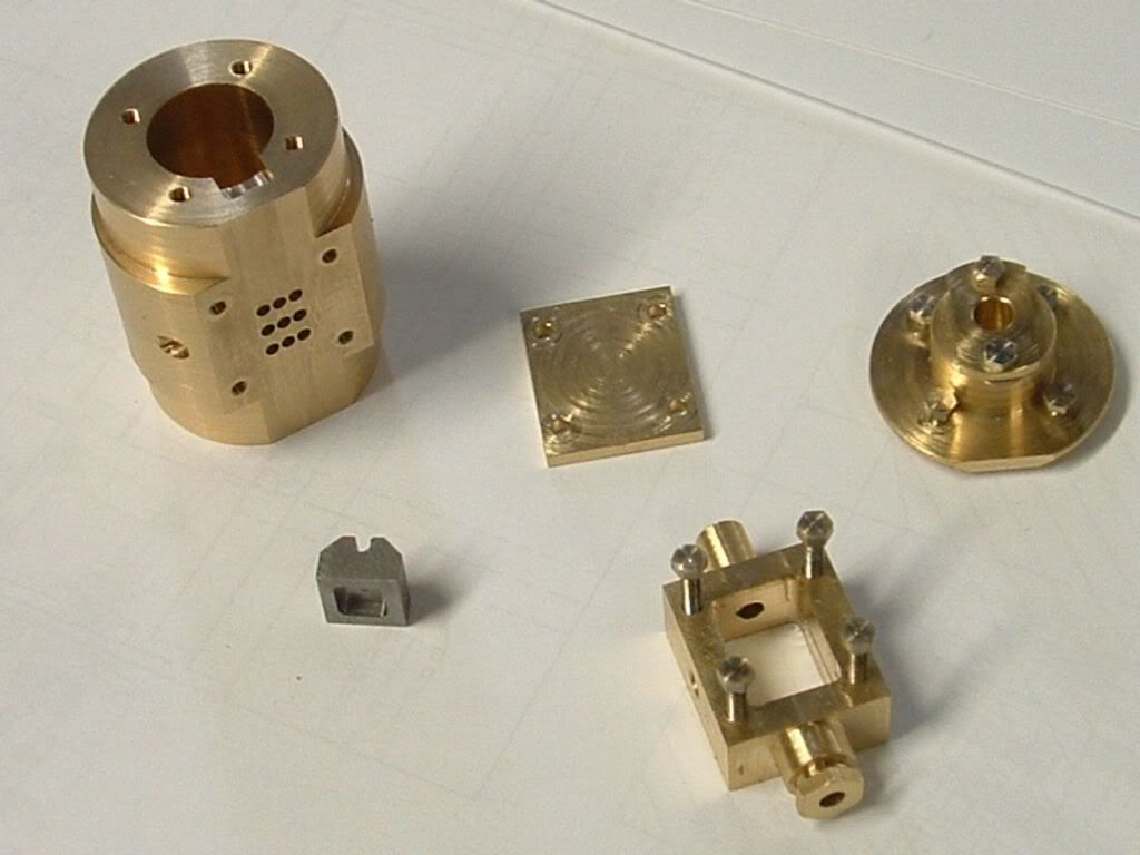
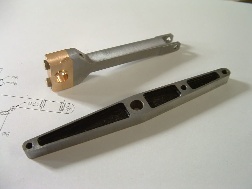
I turned up the web flanges about 0.25mm oversize all round for later clean up machining.

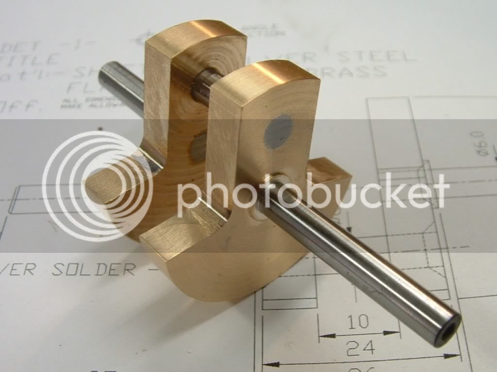
I also pitch drilled (reamed) some 6mm dia reference holes to form the corner rad and act a reference for relocation later (top left in photo) plus M6 tapped holes in the opposite flange so I could bolt everything together using turned sacrifical spacers for the correct gap between the webs.

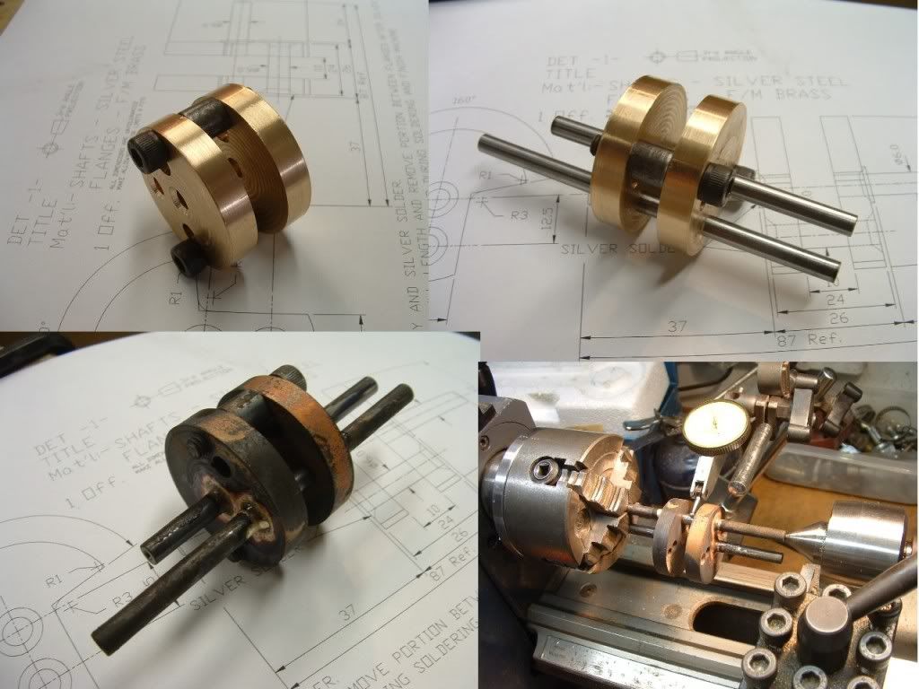
I make the big end axle about 20mm longer than the main axle at the "short" end for subsequent machining of the eccentric portion (outsde the range of my 4 jaw) and bolted it together for silver soldering.
crank1.jpg

Bottom left - the silver soldered assembly - man it looks ugly.

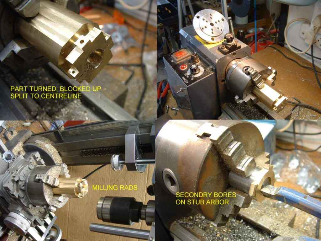
Bottom right machining the area between the webs using the "long" axle in the 4 jaw.

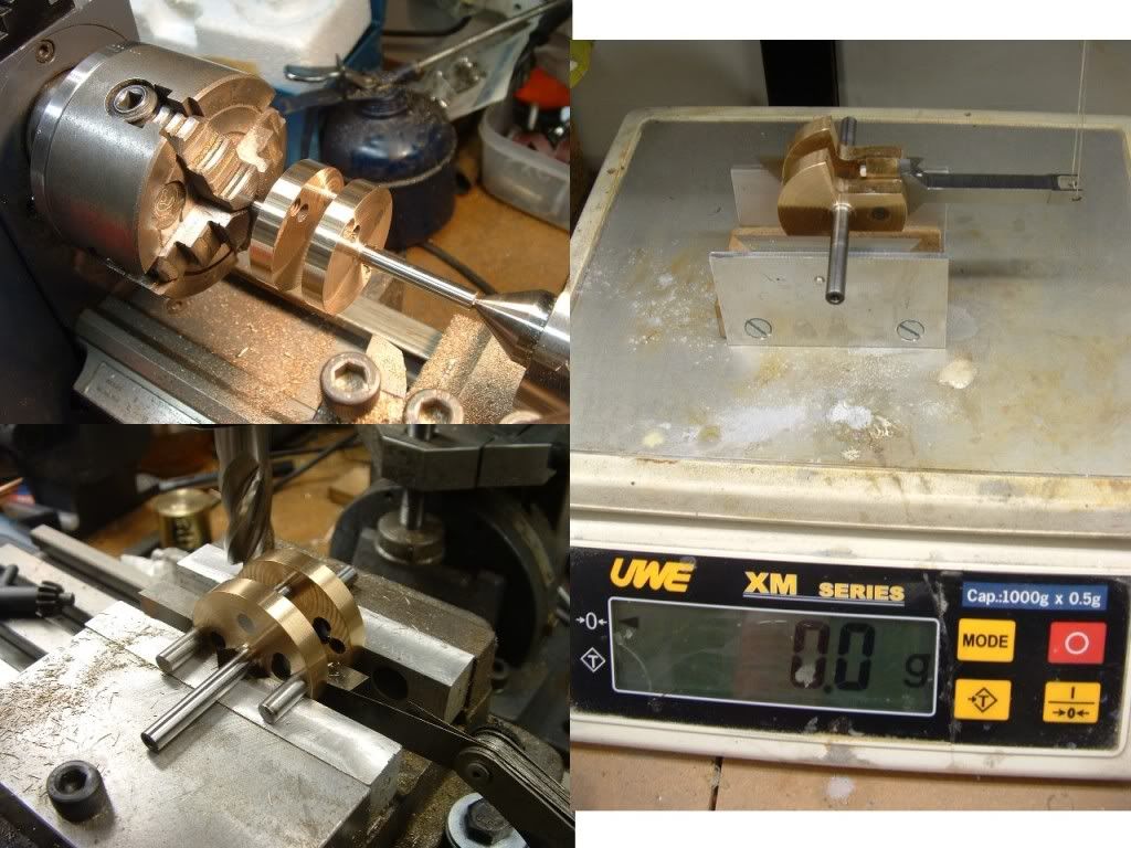
Below - top left - machining the main axle concentric diameters and faces.
crank2.jpg

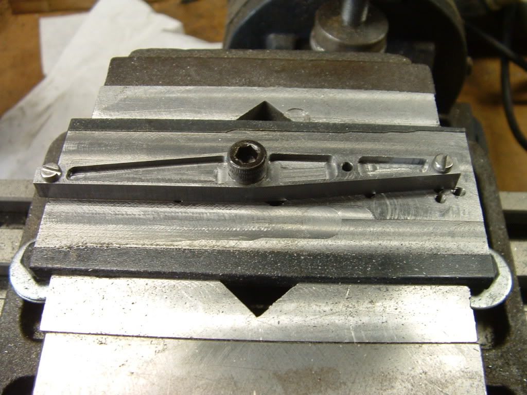
Bottom left above - using the reference holes to orientate the crank for milling the webs (as well as the angles - not shown). Note the 10mm square toolsteel and feeler gauge to fill the gap between the webs so that it can be firmly clamped in the vice without bending the big end pin.

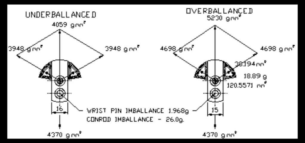
On the right - my ballancing set up :-

A pair of stanley knife blades are near frictionless and the conrod is supported at the big end by a thin thread - obviously this method is only as good as the friction at the big end will permit so it is loose (not fully tightened) and lubricated.

Mount the whole affair on a zeroed scale - if the big end is heavy you can attatch a thin line and pull up - if its light push down.
The value on the scale gives some idea of the mass of material needed to be removed from the parralell portion of the webs (if heavy) or from the offset (if light).

By working up and down you can also see the hysteresis in value induced by the big end friction and you can average the result.

This setup moves to an imballance of about 2.5g mostly due to big end friction - by performing the up down trick I divine I need to remove about 2g from the parallel portions.

Good enough for now - it was designed to be in ballance and it is - (more or less) - but then no plan survives contact with reality. I'll see how it runs before removing any more material.
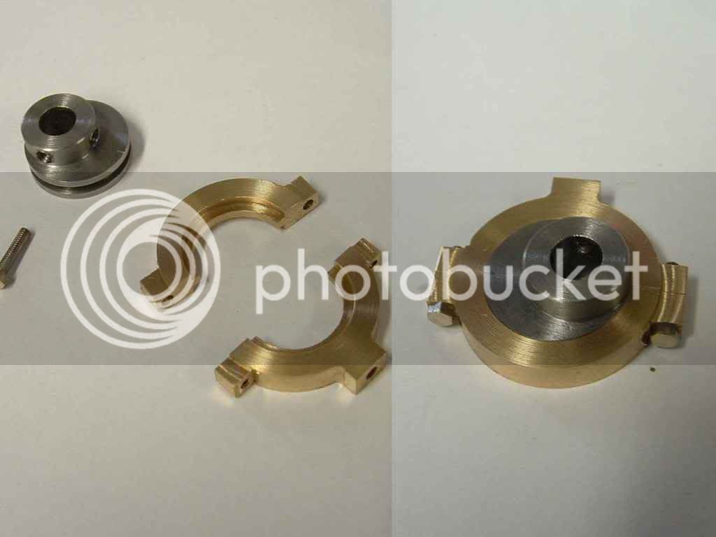
crank3.jpg


The finished crank.

Ken
 
Looks great Ken Thm:

A question if you don't mind... When balancing, don't you need to add the piston as well to compensate for its weight ?

Regards, Arnold
 
As regards ballancing - the piston is not revolving only going up and down (roughly) equal and opposite forces - the same applies to the small end - hence the reason for supporting the small end - we are trying to ascertain only the portion of the mass which works against the rotation for the crank.

If you consider the piston to be moving in (approximately) simple harmonic motion - then its max. accelleration (and hence out of ballance) occurs at TDC & BDC and at mid stroke it is zero (about to change from accelleration to decelleration) if you attempted to counter this with an imballance on the crank it might null out some of the up & down forces at TDC & BDC at the expense of introducing a lateral out of ballance - which will be worse for most of the stroke than the error you are trying to correct - so it doesn't work.

The best solution for the piston imballance is to have two (or pairs) working in opposition to each other.

To be sure there are a number of other dynamic forces at work and the up down motion is not simple harmonic and can only be ballanced by a countershaft. THe more cylinders the more they tend to cancell each other out. Modern 4 cylinder engines and some odd configurations (5 cylinders and V4's & 6's) often use a rotating counterweight shaft (countershaft) to overcome these forces.

Also my setup is a static ballance and not a dynamic ballance which is beyond anything you can come up with at home. However given the symetry of the parts a static ballance should be fine.

It seems to work.

Incidentally I ballance 60000 rpm slotcar motor rewinds on blades - works pretty well - again not dynamic but if its not statically ballanced it is definately not dynamically ballanced.

Ken
 
Thanks Ken - a lot of brain-food for digestion :)
Regards, Arnold
 
Thanks Pat - I would like to see that.

This is what I did (by guessing and checking) ....

The photo below shows the ballancing vectors I did when I redesigned the engine.
It was meant to be slightly "conrod heavy" at the design web parallel of 16mm - leaving plenty of room for adjustment later. (At 15mm it is way overballanced).

Vectors.jpg


Due to some small errors my web ended up at 15.8 and as luck would have it very close to perfect ballance.

The proof of the pudding however...... I'll let you know when it runs.

Attatched drawing is of the reference holes.

Ken


View attachment DUMP1.dwg
 
Ken,

It's looking great! Keep up the good work!!!! I did notice in one of your last post you said it was a 12mm bore but I have it as a 12.5mm bore? I just want to make sure you haven't changed your design. I am getting ready to start on my own cylinder and I don't want to goof it up. Thanks for your help!!! Steve


"If you are using the original imperial drawings - they are not the same - mine has been metricated (not just metricised by multiplying by 25.4) so its now 12mm bore x 25mm stroke - also the valve link and frame are different - so use for info only."


Back
Top