


- Joined
- Feb 17, 2008
- Messages
- 2,328
- Reaction score
- 442
My friend Jim, who lives a couple of states over, and I have been building Gauge 1 Locomotives and other powered Gauge 1 items together for about 20 years. Between us we we have built a dozen or so Locomotives plus 6 ditchers (self powered steam powered steam shovels) plus many modification to commercial locomotives. Lots of one of a kind items that have helped each other on also including a Gauge 3 steam locomotive. Our current project is two, one for each of us, Gauge 1 military locomotives used in WW2 for moving supplies around behind the war lines. They were small 0-4-0 gasoline powered locomotives of about 50 horse power.
This thread shows the first metal cut which, starting from the bottom and working up, is the wheels. As this is an outside frame locomotive no crank pins are needed in the wheels.
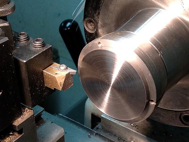
The wheels start life off as a metal blank cut off from 2 inch diameter 12L14 bar stock to about 0.260 inch thick and then faced on one side to provide a smooth back for the wheel. The facing was done in a 2 inch diameter 5C step collet in the manual lathe.
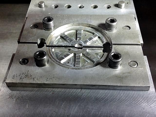
A set of soft jaws was prepared for the mill vice. The photo shows the jaws after they have been used so the spokes show up where the cutter has cut the spokes.
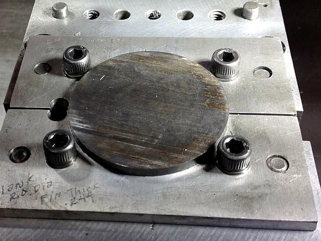
The blank is clamped in the soft jaws with the finished side down.
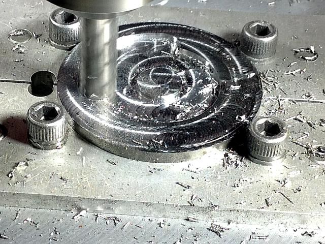
First operation is to surface the blank off to 0.248 thickness which will later be finish cut to 0.244 thick on the lathe. This was done with a 3/8 4 flute carbide end mill using Micro-drop cutting lube to lube and remove chips.
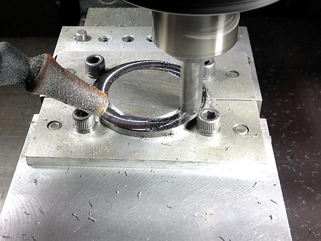
Then the inside is recessed down to the spoke depth and leaving the hub and rim full depth.
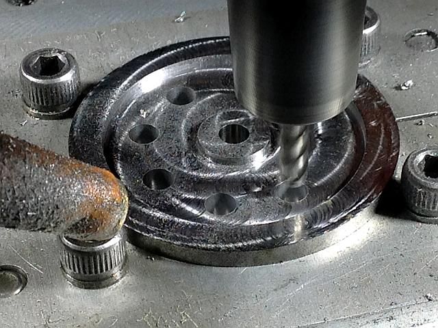
A 3/16 center cutting 4 flute end mill is used to drill the hole for the axle and starting holes for cutting the spokes. This end mill cuts a little under 3/16 inch so the axle hole is reamed by hand on a drill press later.
Then the spokes are cut through the blank and to width with an 1/8 inch 4 flute end mill.
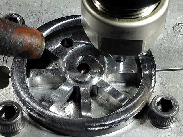
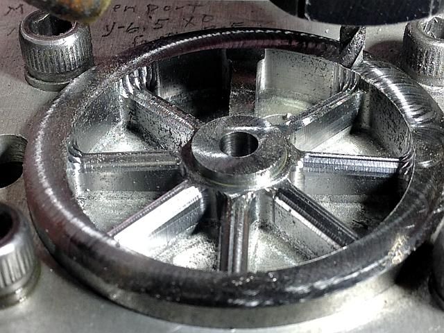
And the spokes are rounded off with multiple passes using an 1/8 inch ball end mill and that completes the milling operations.
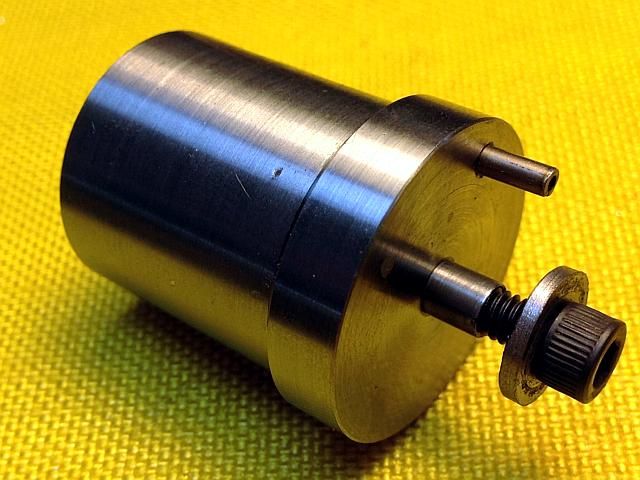
A mandrel is made up to mount the wheels for the turning operations. The stub is 3/16 diameter and the screw is 8-32.
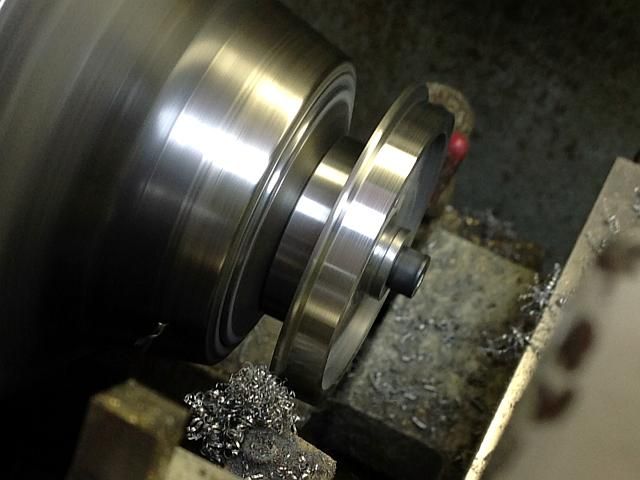
After reaming the axle hole, the blank is mounted on the mandrel in the CNC lathe and the outside face of the rim is
trimmed to the final thickness. The tread is turned with a 3 degree taper and the flange tapers outward at 10 degrees. The radius on the edge of the flange is turned 1/2 way to the finished flange diameter.
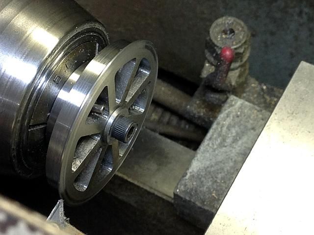
The wheel is reversed and the inside 10 degree taper is cut on the flange and the other half of the radius on he flange is cut.
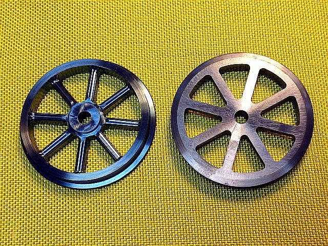
And the finished wheels.
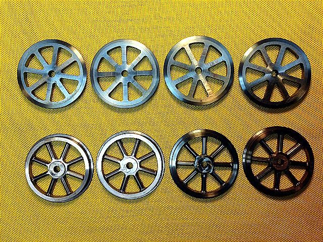
Gail in NM
This thread shows the first metal cut which, starting from the bottom and working up, is the wheels. As this is an outside frame locomotive no crank pins are needed in the wheels.
The wheels start life off as a metal blank cut off from 2 inch diameter 12L14 bar stock to about 0.260 inch thick and then faced on one side to provide a smooth back for the wheel. The facing was done in a 2 inch diameter 5C step collet in the manual lathe.
A set of soft jaws was prepared for the mill vice. The photo shows the jaws after they have been used so the spokes show up where the cutter has cut the spokes.
The blank is clamped in the soft jaws with the finished side down.
First operation is to surface the blank off to 0.248 thickness which will later be finish cut to 0.244 thick on the lathe. This was done with a 3/8 4 flute carbide end mill using Micro-drop cutting lube to lube and remove chips.
Then the inside is recessed down to the spoke depth and leaving the hub and rim full depth.
A 3/16 center cutting 4 flute end mill is used to drill the hole for the axle and starting holes for cutting the spokes. This end mill cuts a little under 3/16 inch so the axle hole is reamed by hand on a drill press later.
Then the spokes are cut through the blank and to width with an 1/8 inch 4 flute end mill.
And the spokes are rounded off with multiple passes using an 1/8 inch ball end mill and that completes the milling operations.
A mandrel is made up to mount the wheels for the turning operations. The stub is 3/16 diameter and the screw is 8-32.
After reaming the axle hole, the blank is mounted on the mandrel in the CNC lathe and the outside face of the rim is
trimmed to the final thickness. The tread is turned with a 3 degree taper and the flange tapers outward at 10 degrees. The radius on the edge of the flange is turned 1/2 way to the finished flange diameter.
The wheel is reversed and the inside 10 degree taper is cut on the flange and the other half of the radius on he flange is cut.
And the finished wheels.
Gail in NM