It has been a while since I posted a build thread here but thought I may as well show one.
It all started when I said in another thread about Nattie*.
"Could not help thinking while I was running this that it would be fun to see if the cylinder could be sleeved to form a water jacket, gears changed to get 1:2 ratio, add a couple of valves into what was the exhaust block (turned on it's side) and a spark plug or hot tube in the head, about 24mm bore should work"
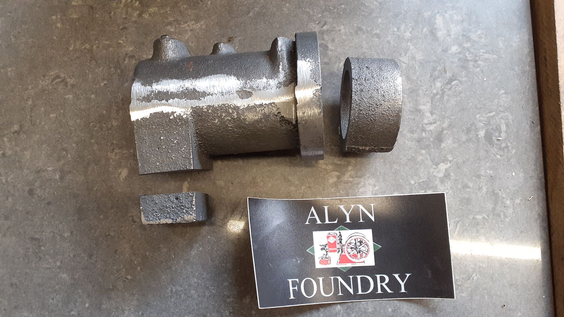
A few months later Graham Corry of Alyn Foundry sent me a pair of gears that he had been applying the special brown coating to for a number of years together with some Nattie castings so I could hardly refuse the challenge to make a sister engine called Gassie:-[
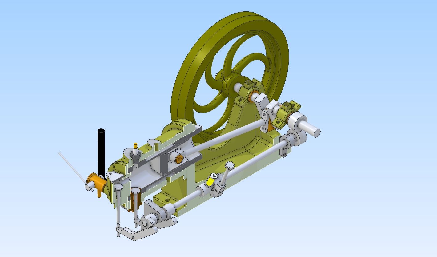
Although this engine does use castings I have put it under "Own design" as I did design the patterns for 50% of the castings and have modified the others together with designing all the remaining bits. This was done over a few evenings with Alibre along the same lines as Nattie which is to have an engine with the look of an early National Gas Engine.
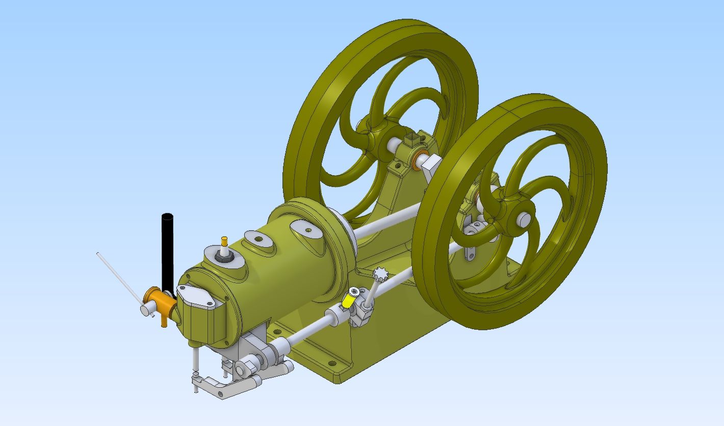
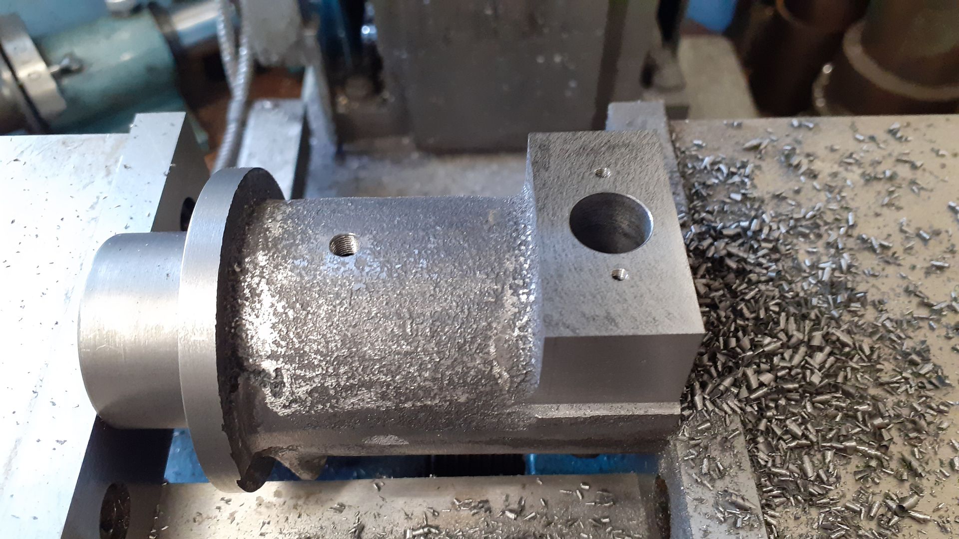
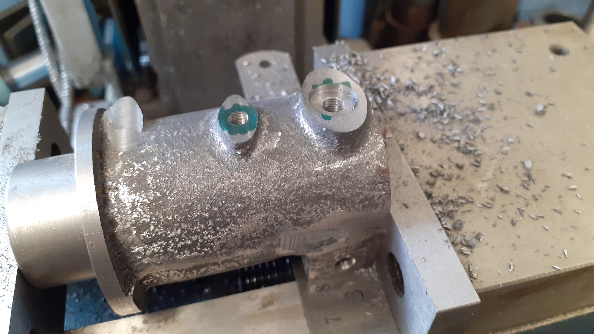
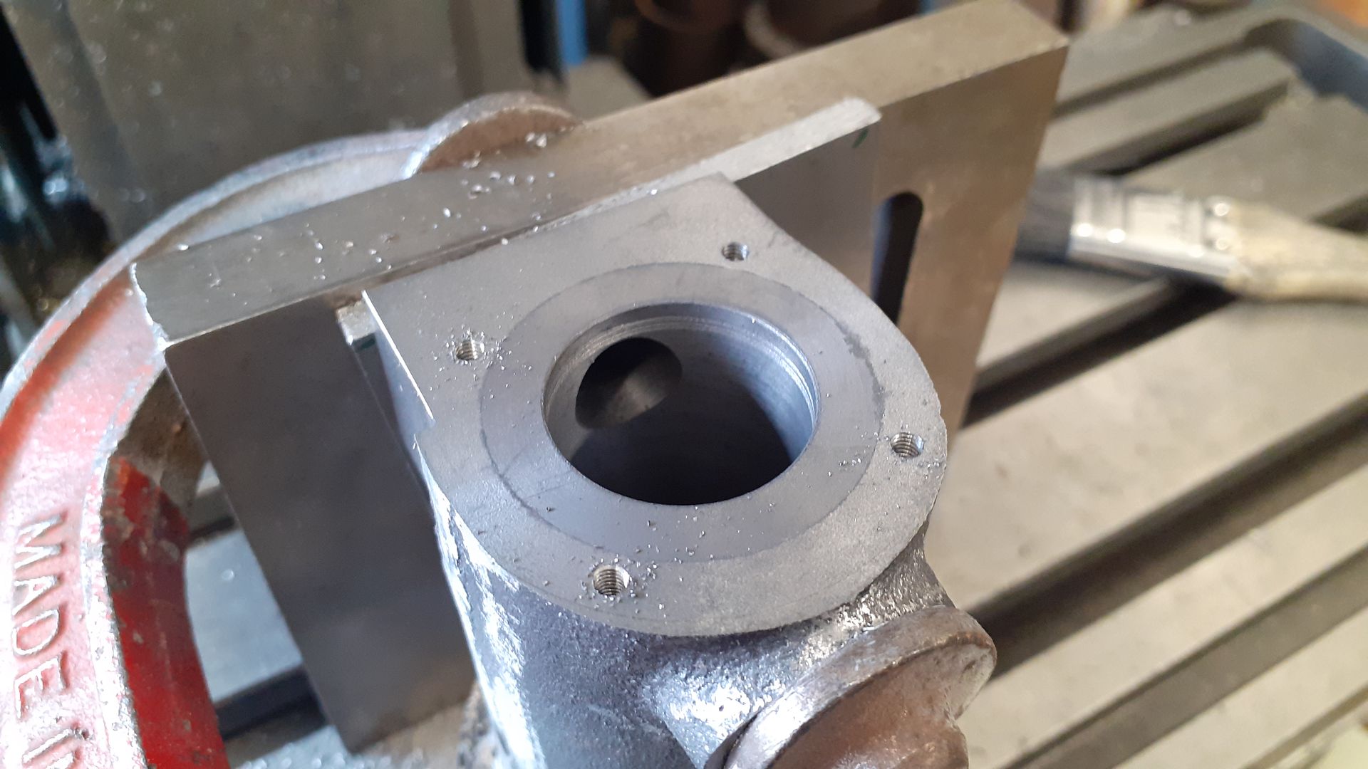
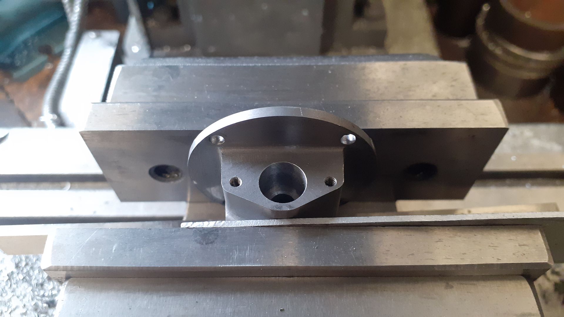
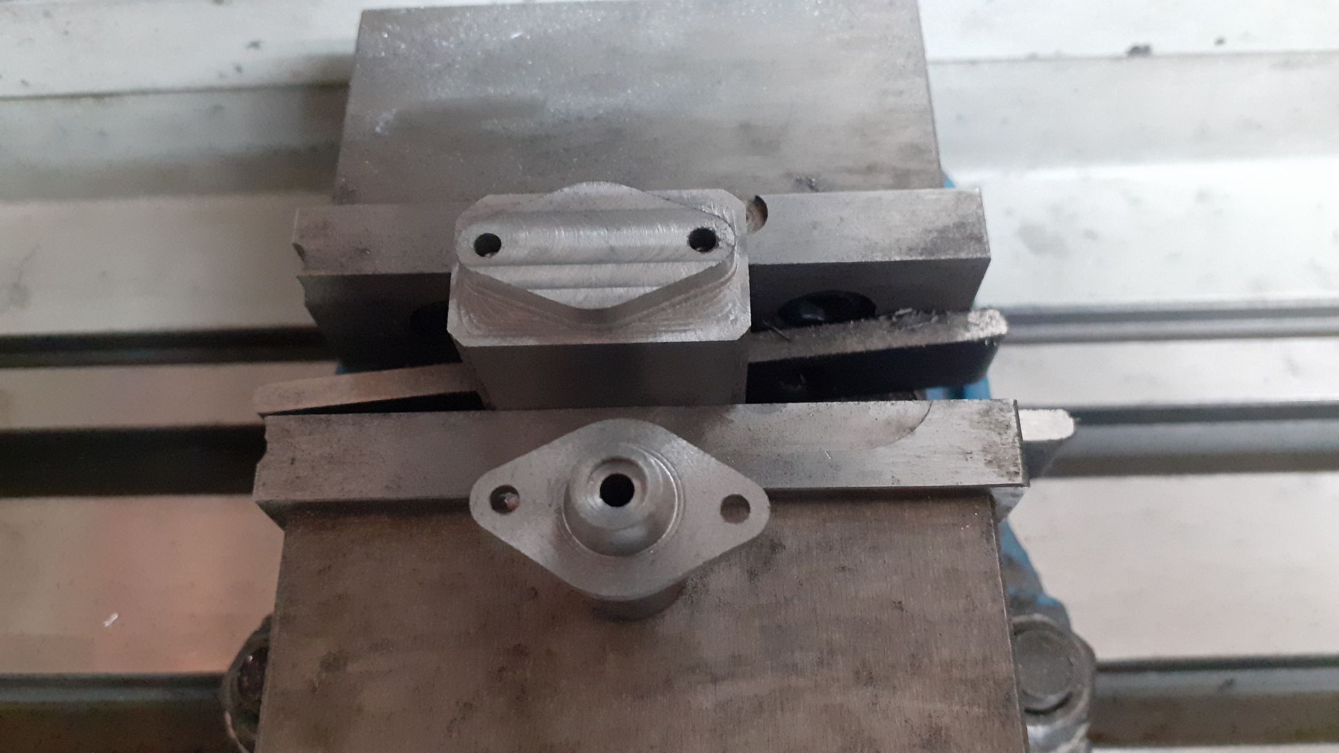
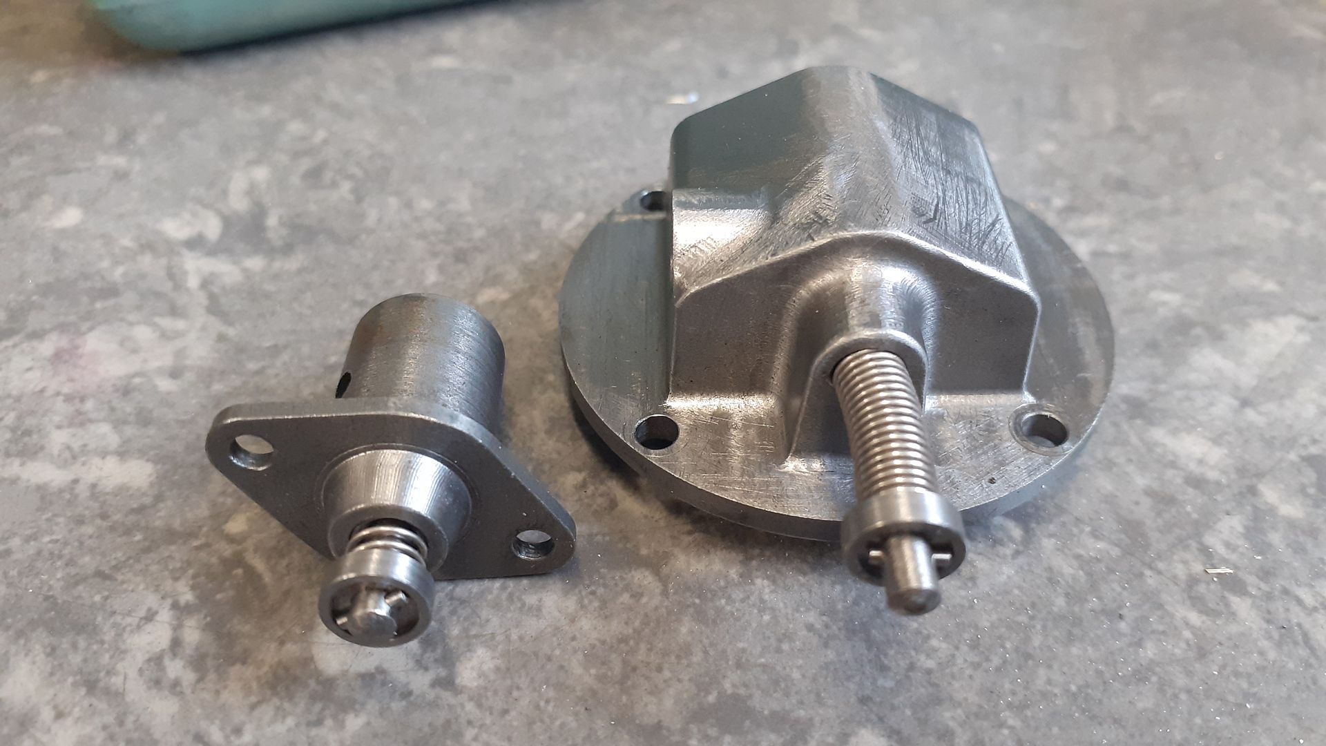
I ended up keeping the exhaust block the same way up as that also kept the various bosses at the top of the cylinder in the right place making use of the rear one for a spark plug as I have seen on some full size engines. A liner allows for water cooling which is via the middle boss and a drilling through the underside. A new head houses the inlet valve and boss for the carb. A larger dia solid crankshaft takes care of the more powerful stroke and a thicker side rod carries the two cams and electrical contact for the ignition.
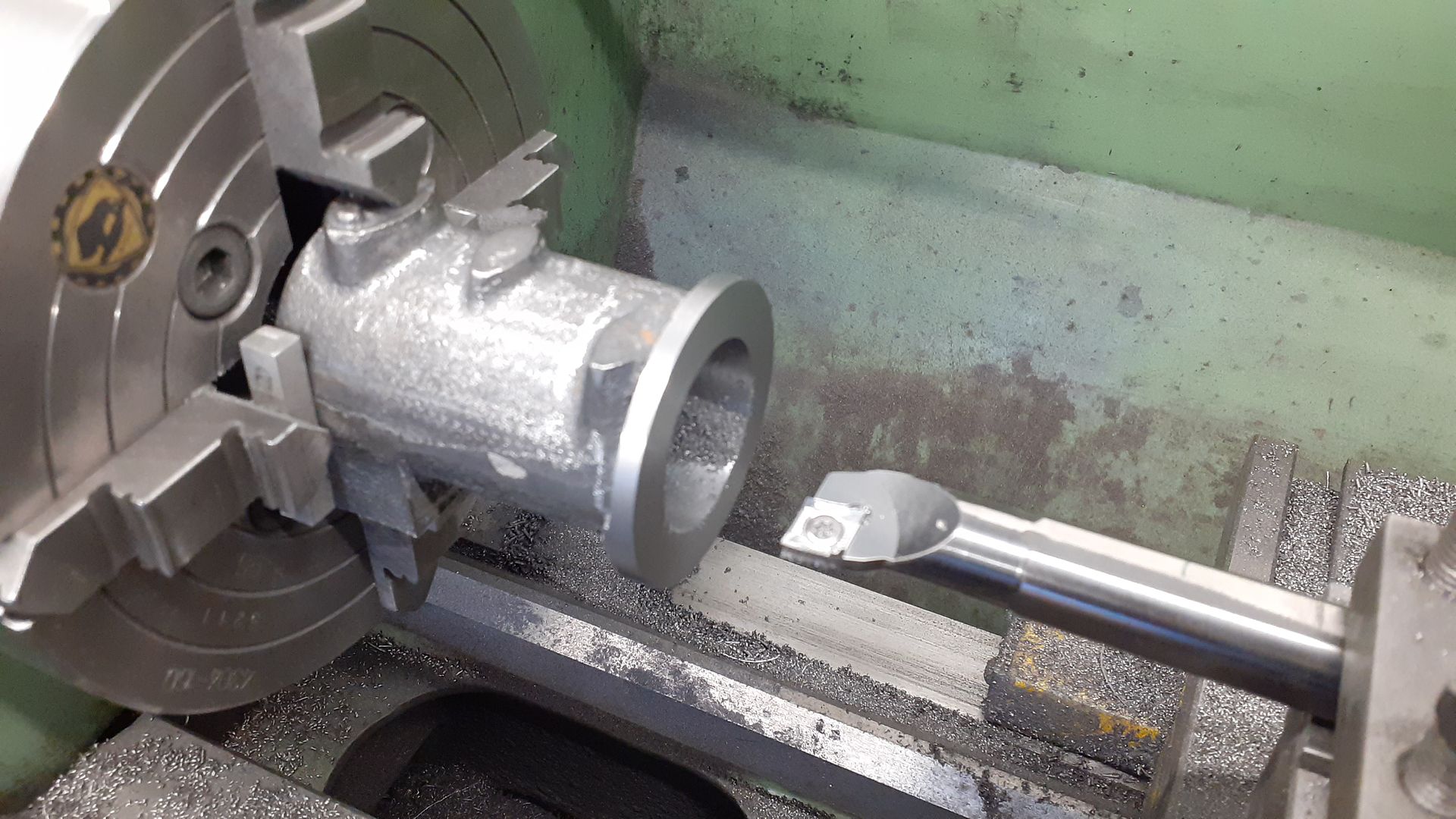
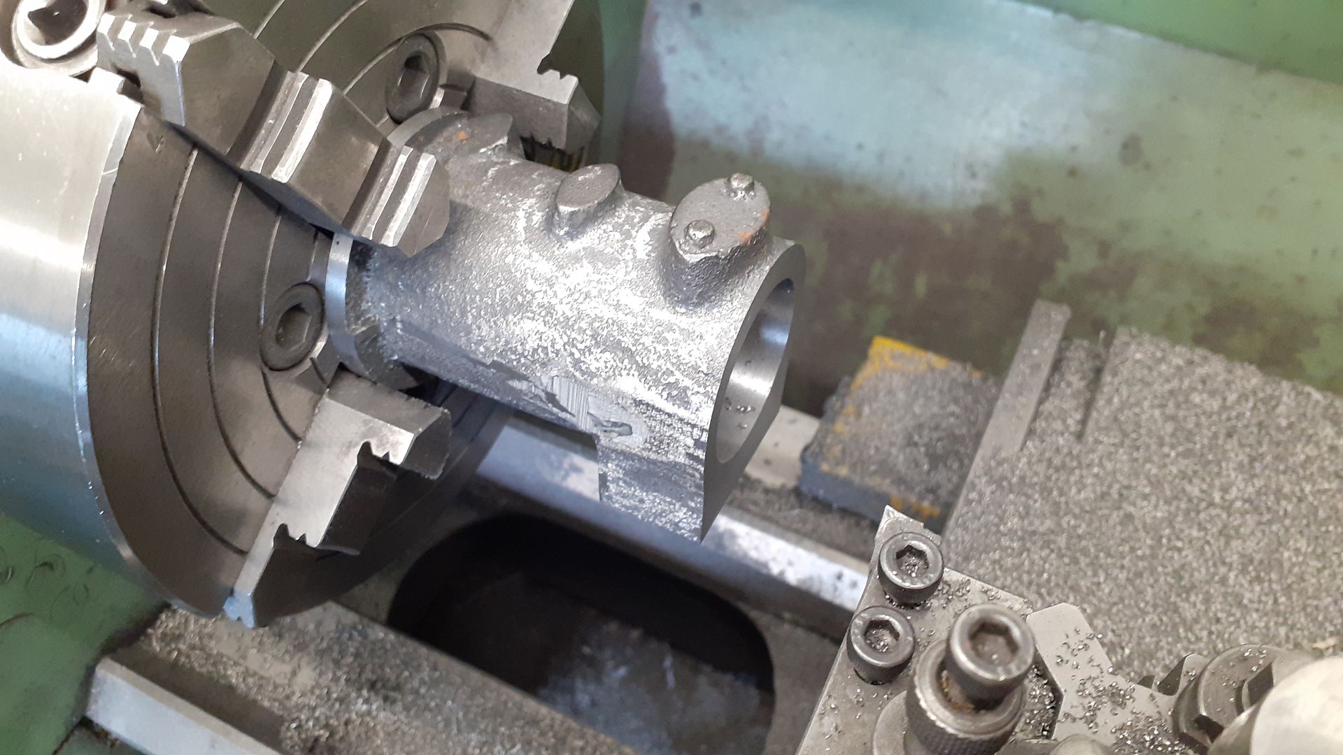
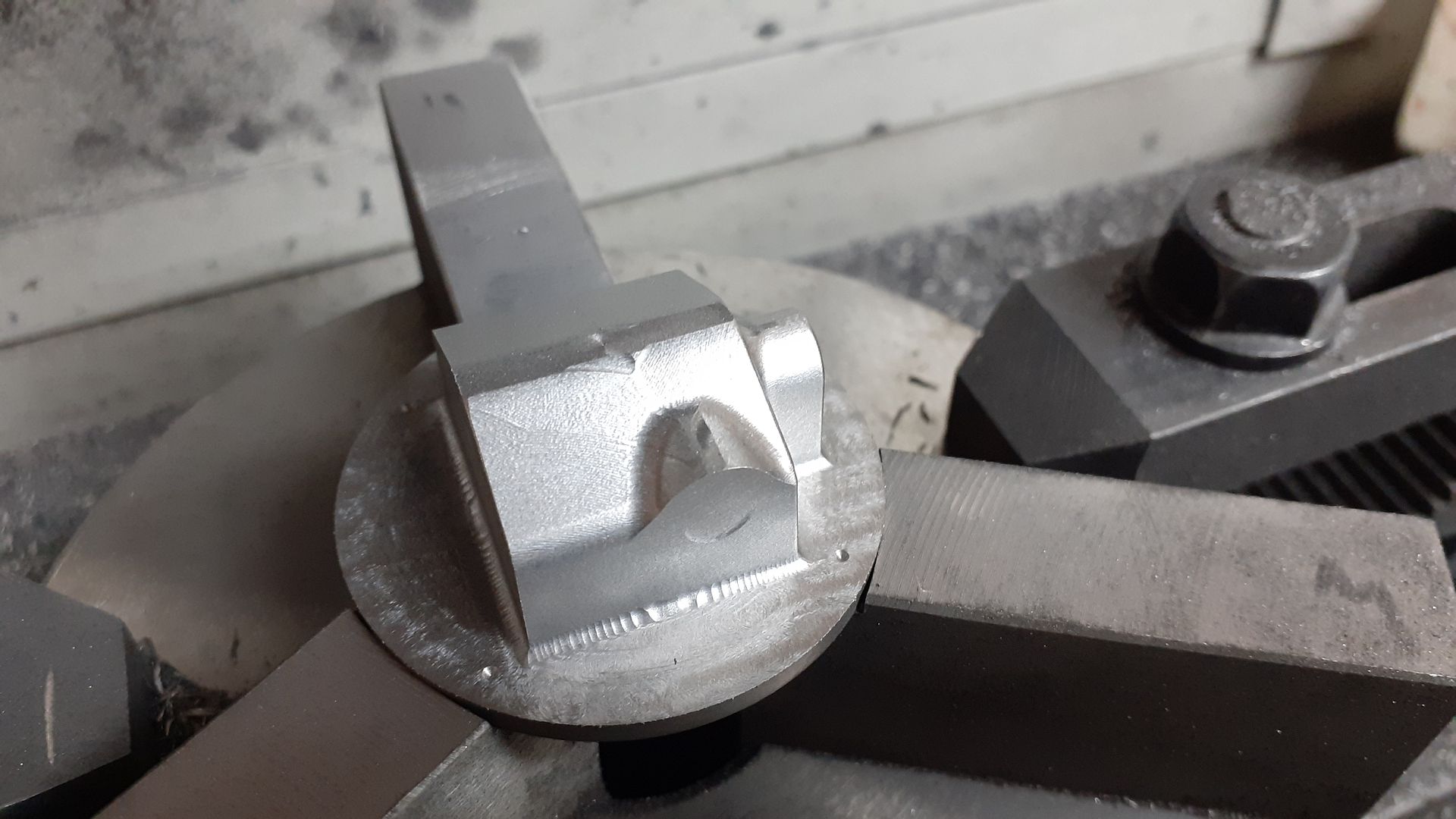
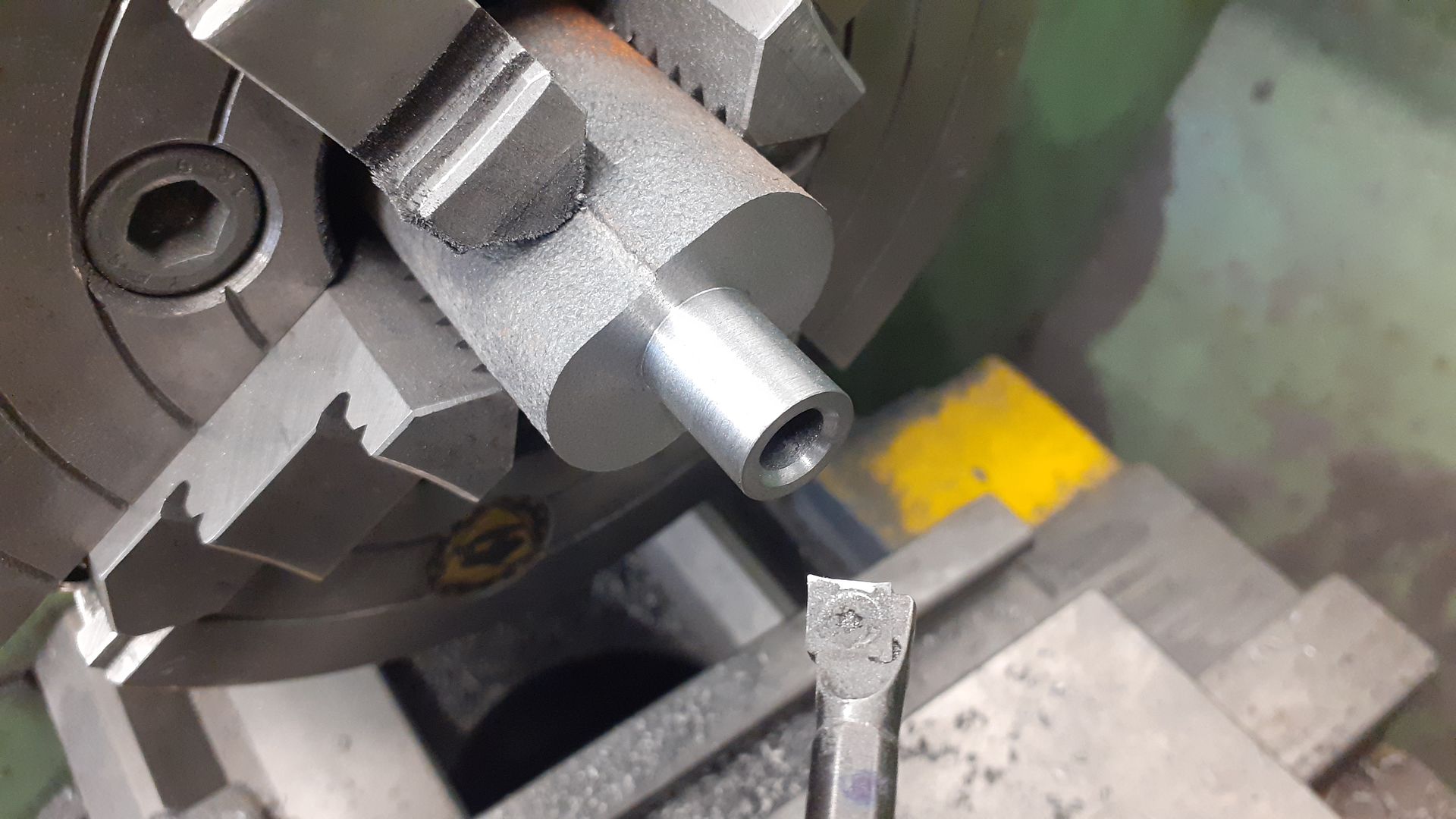
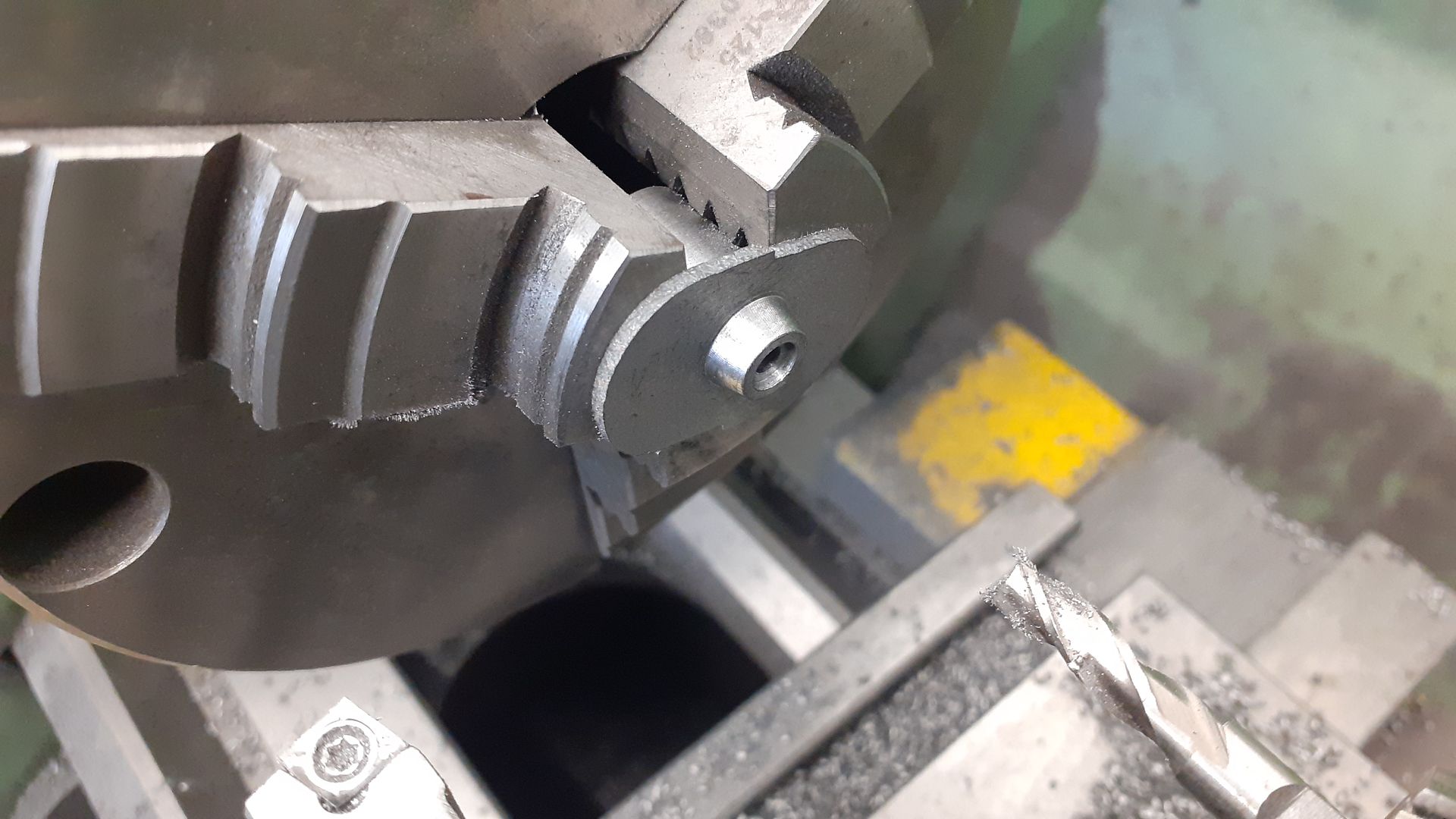
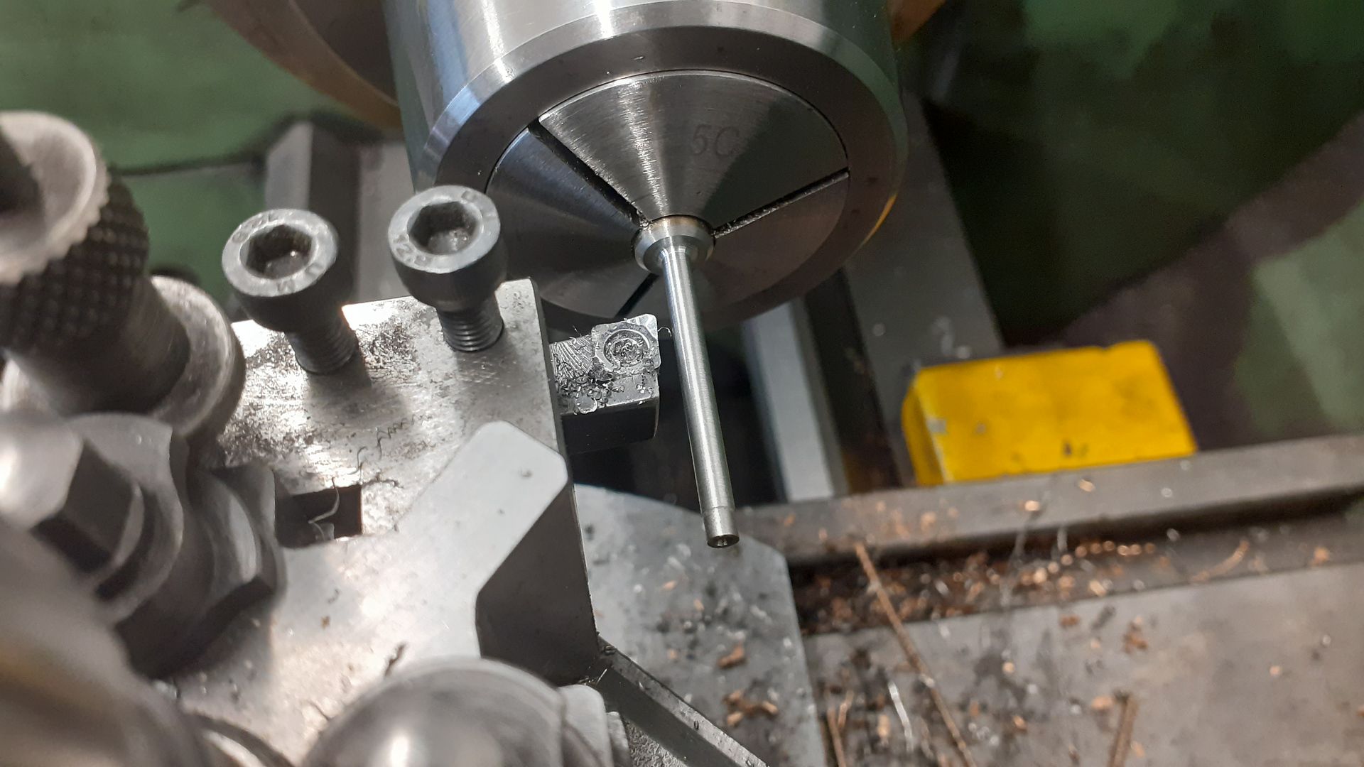
First job was to get rid of what was not needed.
*For those that don't know "Nattie" it is a flame licker very loosely made to resemble an early National Gas Engine
It all started when I said in another thread about Nattie*.
"Could not help thinking while I was running this that it would be fun to see if the cylinder could be sleeved to form a water jacket, gears changed to get 1:2 ratio, add a couple of valves into what was the exhaust block (turned on it's side) and a spark plug or hot tube in the head, about 24mm bore should work"
A few months later Graham Corry of Alyn Foundry sent me a pair of gears that he had been applying the special brown coating to for a number of years together with some Nattie castings so I could hardly refuse the challenge to make a sister engine called Gassie:-[
Although this engine does use castings I have put it under "Own design" as I did design the patterns for 50% of the castings and have modified the others together with designing all the remaining bits. This was done over a few evenings with Alibre along the same lines as Nattie which is to have an engine with the look of an early National Gas Engine.
I ended up keeping the exhaust block the same way up as that also kept the various bosses at the top of the cylinder in the right place making use of the rear one for a spark plug as I have seen on some full size engines. A liner allows for water cooling which is via the middle boss and a drilling through the underside. A new head houses the inlet valve and boss for the carb. A larger dia solid crankshaft takes care of the more powerful stroke and a thicker side rod carries the two cams and electrical contact for the ignition.
First job was to get rid of what was not needed.
*For those that don't know "Nattie" it is a flame licker very loosely made to resemble an early National Gas Engine