Frustrations

Home Model Engine Machinist Forum

Help Support Home Model Engine Machinist Forum:

This site may earn a commission from merchant affiliate links, including eBay, Amazon, and others.
Kaleb,
Thanks for your input. Actually, Steve and I are going to try to show some drawings that illustrate the good, the bad, and the ugly, but that will be in a week or 2.
In the meantime, the drawing you show is good, but could be better, and I will make a few, simple suggestions to show what I mean, but that will also be in a day or 2. Please keep in mind that my intention here is to help everyone, not to be a know-it-all. I just hope that someone can find value in what I offer, or if not, there is the delete button. I'm also certain that there are many here who can add their valuable knowledge and experience to this discussion.
Mosey
 
Kaleb,
Here is a quick sketch of some suggested revisions to make the drawing clearer.
1. Rearrange drawings on the sheet to align them directly over each other
2. Number them so you can refer to them on other sheets, etc.
3. Use better arrows that are easy to connect with the item, less confusing
4. Always have overall dimensions
5. Might like to see where the tapped hole is in plan view, etc.
Mosey

View attachment 40 mm Lathe Dog sketch 1.pdf
 
Mosey said:
Kaleb,
Thanks for your input. Actually, Steve and I are going to try to show some drawings that illustrate the good, the bad, and the ugly, but that will be in a week or 2.
In the meantime, the drawing you show is good, but could be better, and I will make a few, simple suggestions to show what I mean, but that will also be in a day or 2. Please keep in mind that my intention here is to help everyone, not to be a know-it-all. I just hope that someone can find value in what I offer, or if not, there is the delete button. I'm also certain that there are many here who can add their valuable knowledge and experience to this discussion.
Mosey
Mosey I would be interested in your input on drawings. I thinks it is a good idea to have a crash course in making and reading drawings. I sure a lot of us would value your input on the subject.

Regards Don
 
Don,
I hope the little markup I did below of the Lathe Dog is visible. Let's find a drawing with some meat to it, that I can take a look at. Do you have any that we might work on?
Mosey
 
The navy blueprint reading manual covers the basics. the main thing to learn is lines what do they represent.
projections and views and the section on machine drawing. there is lots of stuff in there that may or may not be of use to the folks hear like aircraft stations plumbing symbols and architectural drawing. but that is in the book too.

http://www.hnsa.org/doc/pdf/blueprint.pdf
Tin
 
Mosey said:
Don,
I hope the little markup I did below of the Lathe Dog is visible. Let's find a drawing with some meat to it, that I can take a look at. Do you have any that we might work on?
Mosey
By some meat to it,d o you need a drawing that has a lot of errors are just a drawing of parts? I can't supply a drawing with errors. I have a connectiong rod drawing.


Don


View attachment SAMPLE DRAWING_0001.pdf
 
Tin,
That manual is excellent in many ways, though dated before CAD, so it doesn't have the look we are used to today. The part about line standards is very good, we all can follow most of that (except it is infected with the common poor arrowhead types).
Jared,
We don't need one with errors, just one with lots of machine parts drafted. I'm sure we can edit most of what is out there. I will see what we can find.
You will notice that the organization of several drawings on a single sheet is most often poorly organized, and very confusing to follow, ie., the Elmers engines.
Mosey
 
When doing tool design drawings, I always endeavoured to show all overall dimensions of parts so the toolmaker could start blocking up parts straight away without having to add up dimensions. Also made sure that detail dimensions were from one datum edge, having to add up 2 or more dimensions to get the overall size had the chance of errors.

Paul.
 
Mosey, you can download any of mine from the downloads section.

I design machines for a living but for model building I try to keep the jargon and symbols off the drawing. Even for engineering work I find some of the geometric tollerancing to be a PITB - I see no point in issuing a drawing that requires the toolmaker to delve into a number of reference books simply to hand mark up the print with values from tables. I see little point in lableing a hole 7.0H7 when all I mean is 7.0 Ream.

If the part cannot be made from the print - then I have failed as a designer particularly wrt model building (within reason of course).

I typically do a three view 2D General Assembly drawing with each part in a different layer / colour - that way you can turn layers on and off to see where it goes in the assembly.

I copy those components to another part of the sheet for dimensioning and if I make any changes at that stage it is a simple matter to slot it back in to the GA.

After construction I renumber the component parts into the manufacturing sequence which (in my opinion) gives the best sequence of making matching parts.

Similarly all parts are marked "untoleranced, make allowances for limits and fits" which is pretty much the way most modellers approach their projects anyway.

There are better and more correct ways of doing it but I'm trying to make the drawing "accesable" to the nature of the hobby rather than engineering pe se.

At first glance this approach may look a bit cluttered but I find it works rather well.

I've attatched my 6 Shooter Elbow Engine (zipped Autocad *.dwg) as an example if you are interested - the drawings are mostly complete and I will post it to the downloads section once fully finished.

Ken

View attachment ELBOW6.zip
 
IMHO,

All else to one side, the most frustrating thing about model engineering drawings that I have purchased is that not one of them could be made from the plan due to:

Incorrect measurements

The inability for the model to be assembled as drawn.

Having made a couple of designs using 2D Cad and then started to build them it's easy to see how this happens because the real world soon overtakes the drawing board. Without meticulous attention to detail and constant correction the theory and reality soon drift apart. If you are doing this to make money, please make it worth my while to part with same.

I agree with Ken in that rather than write some obscure series of letters and numbers even though oh so correct they may be: mild steel, drill rod, phosphor bronze etc. are IMHO, more readily recognised. As for fits and tolerances, rattling good, sliding, push and shrink/press pretty well cover it.

Having recently graduated to the world of 3D modeling, a lot of the above errors are more apparent. Non the less and even with a layer for each part one part will go together with another in cyberspace that will not go together in the workshop. e.g. I rotated a cam, moved the pushrod to match and guess what the end of the push rod slid quite happily into the rocker arm and the valve did not budge.

I should add that apart from some elementary drawing lessons at school and during my apprenticeship, I am self taught with the aid of a couple of DVD's and the CAD program idiots guide. When it comes to dimensions I use the programs defaults and I'm pretty confident that my efforts in this important area are very amateurish.

Thanks for taking the time to show us the way to better presentation.

Best Regards
Bob
 
Ken,
I have downloaded your 6 Shooter drawings and your Broach, and they are very impressive. I am hesitant to make any comment, except to say that they could be made even easier to use with a few enhancements. If you wouldn't be offended, I would suggest some points to consider from the viewpoint of the guy who wants to make these parts. Let me know.
As you know I'm sure, one of the most difficult things to draft is a multi-part assembly, where you are trying to show parts that touch in reality, but have to be drawn with space or multi-lines to show the separate pieces. I have a set of drawings that I am in awe of, that do just that. They are architectural drawings, but the clarity of the difficult drawing subject is just amazing, and they were drawn in 1977 with pens on paper (Mylar)! I will post a piece of them later.
The one quick suggestion I have for your complex and terrific drawings would be to put each drawing or cluster of drawings on the sheet into a separate lined box. I will also try to post an illustration of that.
Stay tuned.
Mosey
 
Mosey, no problem I'm always open to suggestions.

Bob, My problem with the dimensioning defaults is they don't work for all sizes of object and are a PITB to change (at least on mine there are probably 50 parameters).

What I do is draw everything in real size (to hell with scale) - then when it comes to dimensioning, I scale the part up or down by an appropriate factor - switch on the alternate dimension and set its scale factor - that way I get dimensions and arrows etc. which are appropriately proportional to the drawing. Once I'm finished I scale the whole thing - dimensioning included - to actual values again.

That way I only ever have to dicker with two parameters in the dimensioning menu.

So if Im dimensioning a part 5000mm long and my default lettering is 4mm I would scale down 20:1 so when I scale up again I have 80mm lettering - more appropriate to the part. By the same token I would scale up very small parts.

I would like to hear any other tips.

P.S. I'm sure other CAD packages have ways of handling this way better than my antideluvian ACAD Ver 10.

Ken

 
Ken,
We always draw in model space at real world size. Lettering is good in paper space at whatever scale/size gets you where you want to be (with AutoCRAP). Scale is really only for drawings when they get onto paper.
I will make some gentle notes on what you are doing. Who knows, you might find it helps you get your drawings done. I know that better organization of the drawings keeps me (barely) sane.
More later.
Mosey
 
Thanks Ken,

In model space I always draw full size i.e. 1 : 1 on a world scale.

Rightly or more probably wrongly I only use dimensions in model space to show me where I'm at e.g. how much must I move something x,y or z to position it. For a model, I use 1/16" grid spacing. If I'm drawing say a house, (these are metric here) then I alter the grid to 100 mm spacing and change to a metric template.

My program, (TurboCAD) has a pullout called a "drafting pallet" from which up to 19 different views of a 3D model can be turned into 2D sketches. I have been placing the appropriate?? 2D sketches, in paper space where I set the scale if needed and then annotate and dimension.

To me it's easier to dimension in paper space 12 pt is 12 pt, not say 1ft in model space which when scaled down to paper space becomes unreadable. Of course If I had an A0 plotter rather than an A4 printer I may feel differently. ;D

Best Regards
Bob
 
Ken,
We normally divide our sheets up into a grid with a series of horizontal and vertical heavy lines, putting a single drawing in each of the boxes created. We number the drawings to match their position on the sheet within the boxes.
I've marked up your drawing with a grid, and attached one of mine to show how it looks.
After you've done this, we can go to the next step. I hope you will give it a go.
Mosey
In case you are wondering, my arrowheads don't show due to an Autocad glitch. They are actually 90 degree arrows, and this is an important item for you to apply to your drawings, rather than the long skinny map-style arrowheads. These arrowheads make a big difference in clarity, I think.
Mosey

View attachment sheets.pdf
 
Mosey,
The block framing I agree with - in fact I do that on many (but not all) of my industrial drawings.

On my elbow drawings I have blocked in the optional parts to avoid confusing them with the others - but I could still block in the remainder with a different thickness line - etc.

I've been drawing solid point arrowheads since I started with a pencil - 90° arrowheads make me think "Diodes" and those architechtural obliques I dislike with a passion - ditto outline arrowheads - merely a point of personal preference.

There's no accounting for taste.

Please contine.

Regards,
Ken
 
Have a look at the Chain Hook post by Brian Rupnow to see some pretty nice drawings.
Of course, I have a few tiny suggestions for improving his drawings as well, but basically, they are very clear.
 
I've been working with drawing in one fashion or another a long time in the aerospace and military area. And Ken your drawings for the most part meet the specs. The arrow solid heads are correct, blocking in views over the years have not seen much of. Just my observing over the last 38 years. Now architectural drafting my be different in fact I think it's standards are substantially different.
 
Doc,
When I studied engineering drawing at college, I already had a couple of years draughting behind me. The first lecture opened with a stern warning about doing everything "by the book" but once the lecturer saw my work he said "Oh - I see you've already developed your own style. I'm not going to interfere with that." He was however still strict about technicalities.

Since then much has changed and to some extent I've drifted off into my own world of draughting & design.

I still don't think that drawing standards have caught up with CAD, especially the 3D world (and neither have I).

Mosey - If I "issue" drawings - then they get plonked into a frame with my company details and all the other guff on tollerancing etc. etc. - in the CAD world it doesn't make sense to jamb that around every detail.

My engineering world revolves around one off parts (not production) and I generally work very closely with the toolmakers so to some extent the drawings are dumbed down.

Ken
 
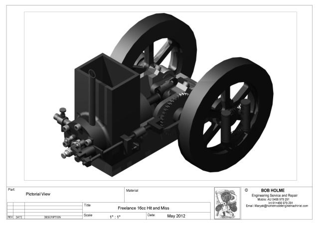
OK Critique away

BobHandM9.jpg


PDF Attached

I will make some more posts with a series of RAR files

View attachment 16cc.pdf
 

Latest posts

Back
Top