First engine (HMEM EZ of course)

Home Model Engine Machinist Forum

Help Support Home Model Engine Machinist Forum:

This site may earn a commission from merchant affiliate links, including eBay, Amazon, and others.

Ryan

Well-Known Member
Joined
Mar 5, 2009
Messages
49
Reaction score
11
My first engine.

Decided to modify the design a little. Just hacksawed and filed out the legs. Two M3 screws through the base.

EZ-step1.jpg
 
And the slightly embellished flywheel. I might paint the indented part of it.

EZ-step2.jpg
 
Hi Ryan, looking good, do you have a lathe but no mill?

Paul.

Correct but I have a large drill press with a compound table. it does okay for very light duty milling. with a collet chuck
 
I have finished the engine. However, I haven't got around to photographing the finished product. In the meantime.....

20140430_161613_resized.jpg


20140430_161443_resized.jpg
 
looks like a nice start into a hobby filled with new engines.

question, is the placement of the crankshaft to connecting rod on the correct side?
 
Last edited:
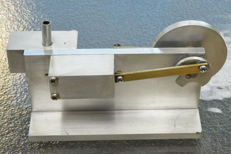
I think he's saying that the connecting rod is normally attached to the small side of the counterweight "pork chop", not in the center of the large side. That's so that the greater mass of the counterweight is always moving in the direction opposite the piston's mass. Yours looks as though it is backwards; is it, or is that attached properly?
 
I just attached it to the large side, because it was in the plans. interesting :)
 
I have seen others on YouTube with the connection this way, as Ryan says, it must be on the drawing that way.

Paul.
 
I have seen others on YouTube with the connection this way, as Ryan says, it must be on the drawing that way.

Paul.

Correct, mine is to the plans and done the same way.

DSC_2515_zpsb96410b1.jpg


One of my future shed outings is to polish this up and make it look nice.
 
I downloaded the plans and yes, this is how the 3D model is shown. The step-by-step instructions use a square instead of this style of crank disc so it's not covered in there.

Now I have this massive urge to build one though. Maybe I'll see if my eldest daughter is interested in having a go on the school holidays.
 
Strange. The imperial drawings do show a rectangular crank disc. The metric plans do indeed show a "Round" crank disc with the crank pin shown on the counterweight side.(?)

John
 
Strange. The imperial drawings do show a rectangular crank disc. The metric plans do indeed show a "Round" crank disc with the crank pin shown on the counterweight side.(?)

John

Now I know why the retaining pin that holds the crank let go at 8000 rpm. It was out of balance :fan:
 

Latest posts

Back
Top