Finger Engine Clutch"

Home Model Engine Machinist Forum

Help Support Home Model Engine Machinist Forum:

This site may earn a commission from merchant affiliate links, including eBay, Amazon, and others.
Here are the parts for the one way clutch.

fingerclutch012.jpg


The actuator freewheels on the shaft. Right now it is aluminum on a steel shaft. I plan to insert a bronze bushing to reduce friction. The diameter of this and all other components is 2".

fingerclutch013.jpg


The clutch cam carrier also freewheels on the shaft and will also get a bushing.

fingerclutch014.jpg


The clutch cams mount on the pivots of the carrier plates and the slots on the cams engage the drive pins of the actuator.

fingerclutch015.jpg


The action of the clutch depends on a small angular displacement between the carrier and the actuator. On the power stroke, the cams are driven outward against the inner face of the drum. At the end of the stroke, the carrier plate stops as the lever comes to a stop and the momentum of the actuator plate moves the pins in the opposite direction and pulls the cams away from the drum providing instant disengagement for the return stroke. The last part that mounts on the shaft is the drum and it is the only part fixed to the shaft.

The gearing is salvaged from a discarded cordless drill and provides a 5:1 increase.

planetarygears008.jpg


I will get some more video after I get it cleaned up and mounted.


Jerry
 
Here is a video of the drum end where there gear action and the rotation is 1:1 with the lever. I know. Its a clunky set screw but it helps visualize the motion.

[ame]http://youtu.be/RkW2mLV0Syk[/ame]

Jerry
 
;D REALLY Good going Cap'n J :bow: :bow:

Makes my little escapade today seem a bit dim, but I'll post it for interest's sake.

Cut a quick 'n dirty ratchet - used a dovetail cutter to get some angles:
normal_IMG_2826.JPG


Made some other crude bits; a new bearing for the column that extends out a ways, a ring to fit on the outside with a hole for an M3 cap screw and a small hole for a pin that will help reversing the ring, and a tooth to engage the ratchet:
normal_IMG_2830.JPG


Assembled it looks like this; a drill bit is still doubling as the reversing pin:
normal_IMG_2829.JPG

The multiple holes in the ratchet tooth was to test the effect of powering the lot at different offsets; closest to the center works best, and it's surprisingly positive.

It does run after a fashion:
[ame]http://www.youtube.com/watch?v=fjXpCuc3Ono[/ame]

John was definitely right; gearing would be best to get some RPM from the flywheel. I was in a bit of double jeopardy this time... Didn't follow John's current advise, but did follow some he'd given me many months ago: "Unless you try it you'll never know". Nothing like a bit of practical work to try something; at least I know I can make a ratchet now :)

I'll try and complete it as-is tomorrow; I need to get cracking on my Cracker and a lot of tool-making jobs again, and am in no mood to cut some gears for now :D

Kind regards, Arnold
 
Hey Arnold,

Nice ratchet! Did you originally plan to hang it under the shaft like that or is that a revision? Looks like it does the job of engaging and disengaging well. John's advice is usually worth listening to, even if you don't follow it. I think the gearing is a good idea but I think you could get the same result with a bigger, heavier flywheel.

Thanks for taking the challenge and following through with a good result. That's one of the greatest things about this forum. A simple question gets a lot of good answers and leads to some new experience.

One of the thins that John said is that there are probably lots of ways to do this and I'm going to explore a few more before I move on.

Jerry
 
Nice work Arnold!!

Loved the shot of cutting the gear!!
I am sure you do not want to make too many of those in the future! ;D

Looks like it works a treat too!

Andrew
 
Thanks Cap'n J & Andrew

Jerry, it's pretty much as I had in mind - I'll add a bit of a description of how things work in a later the post. Looking forward to your other explorations Thm:.

Andrew, that milling shot is all wrong :-[ - Only after I set up everything I realised I'd have to climb mill to cut the grooves at the correct angle - so I went and did just that, but it's not good practice. This was a very quick job; everything by eyeball and gut feel; it took me less than half an hour for doing all the setup and cutting that ratchet gear... Proper gears take a wee bit longer :big:. Mind you, I'm not averse to cutting gears; in fact, I enjoy it and in the next couple of months I'll be doing quite a bit of that, but just not for this build.

Well, the engine is finished, and works surprisingly well ;D
Made some more crude bits:
normal_IMG_2831.JPG


All assembled it looks like this:
normal_IMG_2832.JPG


normal_IMG_2833.JPG


Definitely one of the crudest-looking things I built in quite a while Rof} - I'll call it "Rustic"

But it does run ;D (Apologies; I took this video in my kitchen and the TV was on, so a lot of background sound):
[ame]http://www.youtube.com/watch?v=FqwC1pXNthc[/ame]

Kind regards, Arnold
 
Arnold

Call it crude if you want to but the challenge here was function, not finish. I think you passed on the function part. As far as finish goes...not too shabby. At least it's got all the necessary parts. You have shamed me into getting this thing FINISHED!

I seem to have a problem with that. I get to a point where something works, and I want to tinker with it until I works better. This project is a good example. I started fiddling with the clutch and discovered that there was a small amount of friction between the carrier plate and the drum, even with the cams retracted so I fixed that and then the clutch didn't work at all.

It turns out that this friction was providing the energy to engage and disengage the clutch. I guess that would be OK except that the energy to disengage the clutch was coming out of the flywheel. Not much energy but then, every bit counts.

The aluminum carrier plate just didn't have enough mass to drive the mechanism the way I thought it would. I thought that might be a problem when I was building it but when I assembled it and it worked, I forgot about it. Well it worked but not the way I designed it and not the way I explained it in my last post so I had to fix it.

Here is the fix, a cast iron rim added to the carrier plate to give it the needed mass:

fingerclutchrim023.jpg


It came from a surprisingly convenient source.

fingerclutchrim022.jpg


Lowes cast iron plumbing parts are just that, CAST IRON. Not the galvanized cast steel that most plumbing supplies are. It added the needed mass and the action is greatly improved. You probably can't tell the difference in the video but the feel is unmistakeable.


<VIDEO>


Now I can get to the spring, the stop, and the base.

Jerry
 
And so it goes on, at each step a little improvement.

You guys are doing a great job of solving the problem, I just wish I could be in there with you.

I think you have both solved the drive problem perfectly. A purchased one way clutch bearing could do no more than what you gents have achieved.

It is now a matter to get the flywheel to increase in speed at each stroke, rather than frantically using the treadle just to keep the flywheel turning.
Jerry's is almost there, shame you couldn't have got a bit of a higher gearing in there, but if you wanted to, you could call that a project achieved.

Just by tinkering about like this (I know you have put a lot of work into them) I think both of you have learned something about problem solving. Maybe you didn't learn a lot, but I bet both of you enjoyed the challenge.


John
 
John

Thanks for the comments. This has been a fun challenge. I'm almost there and that has been the story of my life. This finger engine may never be finished but I was much more interested in the clutch than I was in the engine so I'm going to call that part finished. More gearing might help. I salvaged the planetary gears from a battery powered drill and only used half of it. The original gear set was a double reduction type where each gear set gives a 5.5:1 ratio so if I use both gear sets, it will give a ration of 30.25:1. That will really spin the flywheel or it may require more input torque than the clutch can handle. I think I will try another type of clutch mechanism before doubling up on the gears.

The two shoe cam clutch could be improved. Different material for the drum and the cams and a little different angle on the slots might give improved performance but I'm going to try something else. For my next trick, I'm going to attempt a "sprag clutch". This is another type of over running clutch that uses small wedges between the driving and driven parts that release when the parts change relative motion.

I have some ideas on doing this but if anyone has done this or has any some thoughts, please weigh in. This may be more difficult than I think. Clearances, angles, and shapes, Oh MY!

Jerry 1360
 
Thanks John & Jerry

John, yes, I did learn quite a bit actually - and it definitely is a nice challenge to carry on with in future. I have an idea on how to make the clutch double-acting and I'll be keeping on the lookout for a set of suitable gears to gear the flywheel up a bit. And trying to figure out a way to make the flywheel run freely rather than have the gears still engaged when the pedal is stopped. Lots of tinkering to do on a rainy day ;D

Good going Jerry Thm:
I also considered the sprag clutch, it's a nice challenge to figure out. Gave up on it though; it would leave quite a bit of friction going without some way of positively disengaging it.

Kind regards, Arnold

 
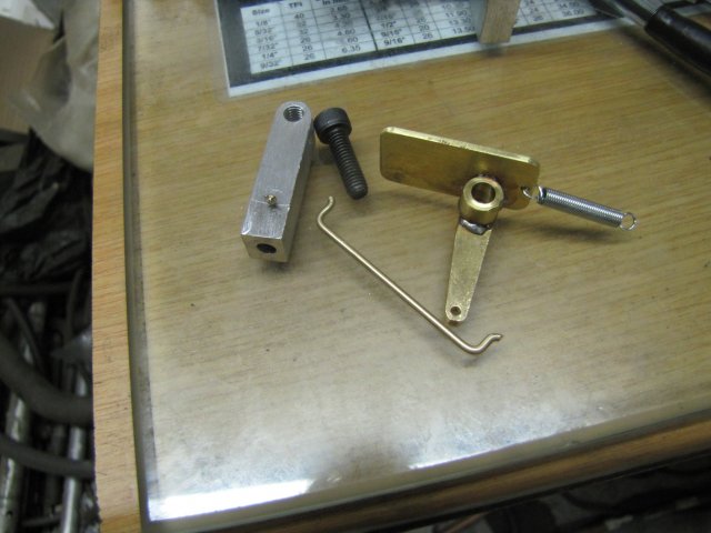
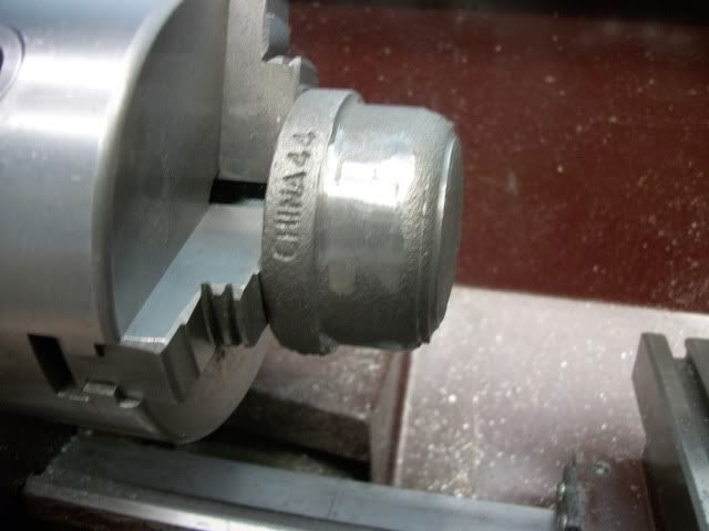
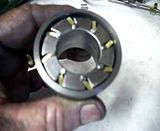
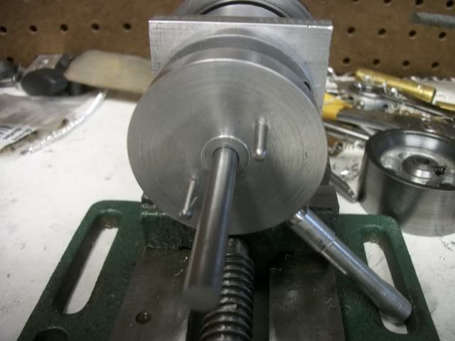
Here is my first attempt at building a sprag clutch.

sprag006.jpg


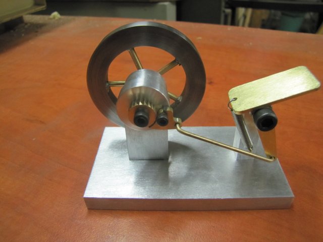
It worked very well much of the time. Other times it worked not at all. It would refuse to lock up, and then for no apparent reason, wham! It would lock and refuse to release. For a first attempt, I was surprised it worked at all. There are so many variables! Angles, shapes, clearance, etc. I won't bore you with all my rejected ideas. In the end, this design won out because of the available material. I decided on cast iron for the inner and outer races because it is cheap and readily available. The local source for this is the plumbing department at Lowes. Imported Chinese couplings, bushings, and plugs in various sizes. Much cheaper than brass or bronze and harder and slicker than aluminum. I would have liked to use cast iron for the sprags as well but I couldn't think of a way to produce the small shape needed.

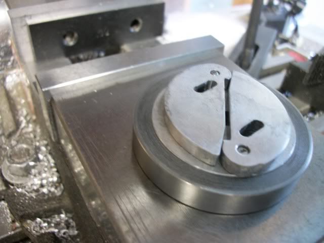
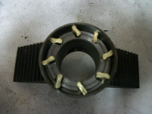
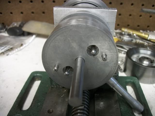
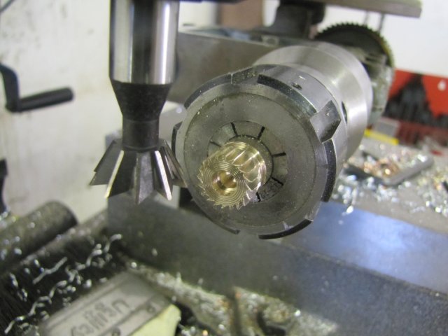
I decided on brass for the sprags when I found a strip with a rectangular cross section 1/4" x 3/32". For this attempt I actually milled concave faces and rounded outer edges to produce the "8" shaped cross section that I was familiar with in commercial clutches. I found out later that is really not necessary. These little brass sprags fit loosely into angled slots on the inner race. There is no spring pressure to press them against the outer race, They just sort of flop around in there and when the relative motion is in the free direction, there is plenty of clearance. About .020". When the movement reverses, the lock-up direction, the little brass sprags stick there heads up to see whats happening and wedge themselves between the races. Sometimes. Other times they would get stuck in the laying down attitude due to imperfection in the shape of the sprags and irregularities in the inner end of the milled slot. Other times, they would lock up but one or more would pivot over center and then refuse to unlock.

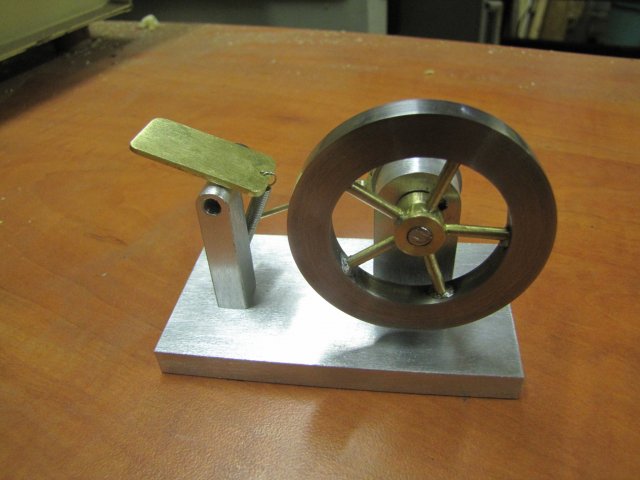
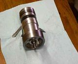
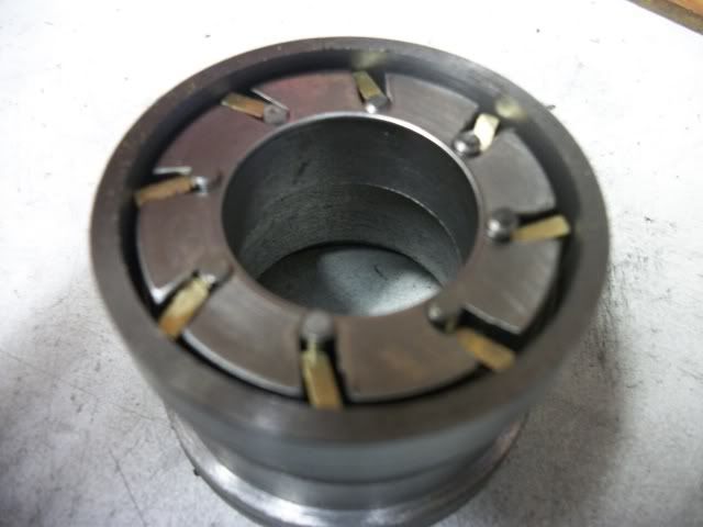
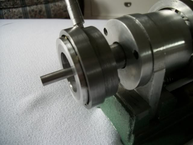
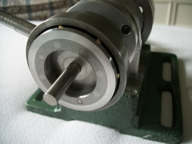
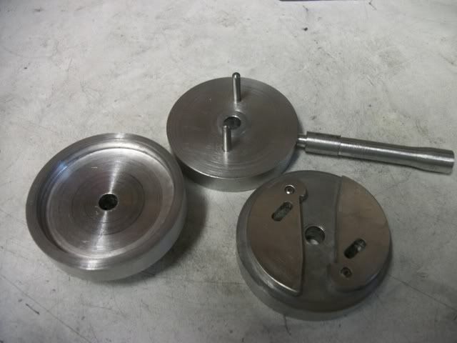
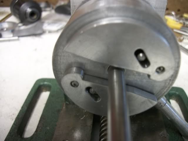
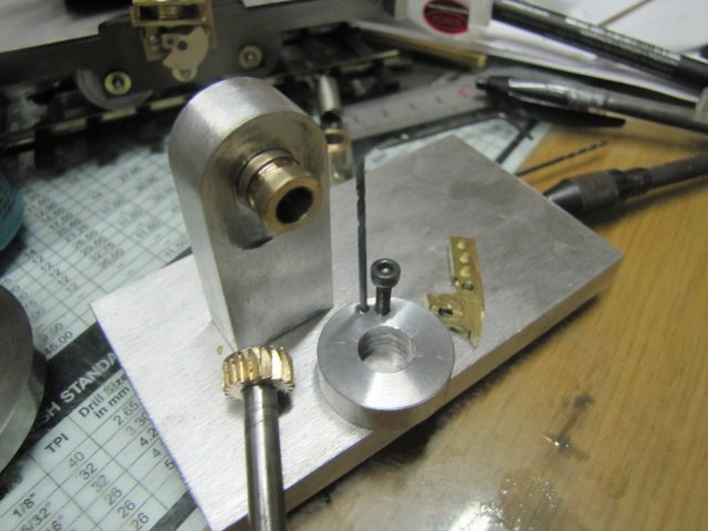
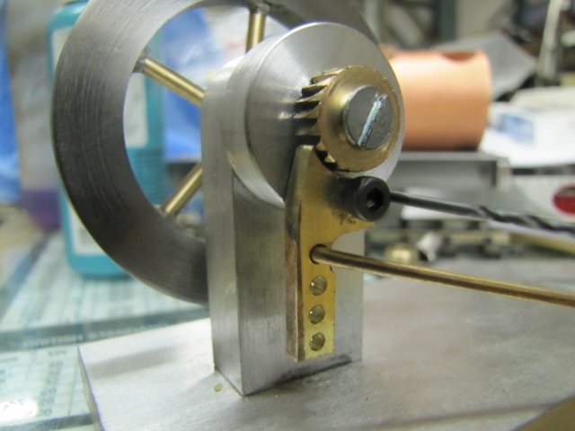
Here is my second attempt at building a sprag clutch:

ASprag007.jpg


In this version, the inner end of the slot is stopped with a polished 1/8" Stainless Steel rod. This gives improved control of the slot length and gives a line contact with the inner end of the sprag against the polished face of the rod. I made no effort to shape the sprags, except to file a bevel on the inner end. The function of the bevel is to keep sprag flush against the pressure face of the slot, preventing it from going over-center and insuring instant release to freewheel.

I will try to draw this up for a clearer understanding, but for now, here is a video. As you can see, my hands and the machines are covered with cast iron powder.

<VIDEO>


As you can see, my hands and the machines are covered with cast iron powder. Tomorrow will be a big cleanup day, and then I will work out all the fiddly bits like bearings, shields, shafts and retainers.

Jerry 1530


Thanks for the complement, Ken. Cast iron sure is pretty when its polished but what a mess it makes of the machines.

The sprag clutch is finished and mounted and is a big improvement over the cam clutch. It is more compact, has much less friction in free wheel, much quicker lock-up and release. I can actually get good torque transfer with only about 10 degrees of lever action.

bSPRAG007.jpg


bSPRAG006.jpg


Batteries died before I got good video but I'll try again next week.

Jerry
 
To all

I like the way you have taken the finger engine to new heights by using a clutch. It is plain to see that you all have put a lot of thought into the design of this clutch. Each taking a different path to the finish line. All are to be congratulated for stepping up and taking the challenge. :bow: :bow:

Cheers :)

Don
(1700)​
 
I did not really think that mentioning a clutch type mechanism would receive this kind of genius!!!!

It is amazing to see what happens on this site and the enthusiasm everyone puts into a thought or comment!

When i get around to building one i think it will just be a standard version! ;D
Maybe the clutch version will follow in time...

Andrew
 

Latest posts

Back
Top