Exhaust Valve Timing

Home Model Engine Machinist Forum

Help Support Home Model Engine Machinist Forum:

This site may earn a commission from merchant affiliate links, including eBay, Amazon, and others.

Brian Rupnow

Design Engineer
Project of the Month Winner
Joined
May 23, 2008
Messages
14,969
Reaction score
8,250
Location
Barrie, Ontario, Canada
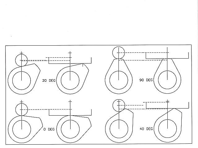
I must admit, I haven't put a great deal of science into the design of the exhaust cams on the two engines I have designed from scratch, the "Rupnow Engine" and the "dual opposed piston" engine. With the "Rupnow Engine" I copied the cam profile from the Kerzel hit and miss engine, and I got lucky.---It ran. The dual opposed piston engine runs, but not the way I ultimately want it to. First I am going to tell you what I know. Then we will delve into the arcane science of cam design. So---This I know. When you have built a new 4 cycle engine from scratch, be it from someone else's proven design, or from your own design the first step in setting it up to run is to set the valve timing. The valve is driven either directly or indirectly by a cam, which revolves at 1/2 the speed of the crankshaft. The cam gear is attached to the camshaft, or else it rotates freely on a stub-shaft with the cam attached to the face of the gear, but either way, it meshes with a gear on the crankshaft. The gear on the crankshaft is not keyed in place, but is generally held in place on the crankshaft by one or two set screws. We are only concerned here with rotational movement, not movement parallel to the centerline of the crankshaft. With the cam lobe not providing any lift at all on the valve, use a feeler gauge and set the gap between the end of the valve and the lifter (or rocker arm) at about 0.010". The engine is then rotated by hand in the direction of rotation you want the engine to run. The set screws holding the crankshaft gear are not tightened down at this point. You want the piston to be moving from top dead center towards bottom dead center. About 1/8" before the piston reaches bottom dead center, stop turning the crankshaft. Rotate the crankshaft gear in the same direction with your fingers (it is loose on the crankshaft) and as you do the cam gear will rotate in the opposite direction. When the lobe on the cam just begins to lift the valve pushrod (a point that you can definitely feel, as there is resistance to the valve lifting created by the valve spring), stop and lock down the set screws in the crankshaft gear. Now your valve timing is set. As the piston moves that final 1/8" to bottom dead center, the valve begins to open. As the piston travels from bottom dead center towards top dead center, the exhaust valve will fully open to let any exhaust gas in the cylinder be pushed out thru the exhaust valve to the exhaust pipe. As the piston approaches top dead center, the valve should begin closing, and by the time it reaches top dead center, the valve should be fully closed to begin the intake stroke. This means that the "lifter" has raised up on the leading edge of the cam, skated across the major diameter at the end of the cam, and rode back down the other slope of the cam and returned to the portion of the cam which provides no lift. Now--Here lies the mystery. On low speed engines such as mine, both sides of the cam are a straight line that lean in towards each other at the major diameter area of the cam which provides maximum lift. The secret of just how much they should lean in towards each other is directly related to the number of degrees the crankshaft has to rotate to carry the piston from bottom dead center to top dead center, which should, in theory be exactly 180 degrees. I have set the opposed piston engine up so the valve is opening at the correct time. However, I find that the valve is closing much sooner than it should as the piston travels up the cylinder towards top dead center on its exhaust stroke.--This means I am going to have to come up with a cam profile that has a wider area of "maximum lift" than the profile I am currently using. I hope this is making some sense. If anyone with experience in the development of cam profiles wants to speak up and educate me somewhat on this, I would greatly appreciate it.---Brian
 
Last edited:
  • Like
Reactions: gus
Hi Brian,
Cam design is an extremely complex science and far too involved to get into here so for the sake of simplicity here's what I can tell you.
What you have described would be known as very mild cam timing and should work fine for a hit and miss engine.
Normally on a 4 cycle engine with both valves operated by the cam the timing would be different and calculated by the working rpm of the engine. Here again for the sake of simplicity the exhaust valve should open around 30 degrees before BDC. By this time the fuel charge has done it's work and with the valve opening at this point is allows the exhaust gases to get a head start on exiting.
Now the piston is heading toward TDC. About 30 degrees before TDC the intake starts to open. The reason for this is to allow the moving exhaust gases to help pull the intake charge into the cylinder. Now the piston moves past TDC to about 30 degrees and the exhaust closes. The reason for this delay in closing here again is the scavenging effect of the flowing exhaust gases and the fact that in 30 degrees of crank rotation there isn't much vertical movement of the piston. Now the piston is headed back to BDC with the intake open. It stays open about 30 degrees past BDC so that the inertia of the moving air/fuel charge has a chance to fully fill the cylinder.
As I said these numbers are only approximate due to the many variations of engine design, but you get the picture.
gbritnell
 
Brian, some sketches in SW will have valve timing sorted in a few minutes, no? Just keep in mind the valve lash you're setting to be accurate. .010" of lash doesn't sound like much, but depending on geometry (small lift) the result is what you see. I would let the exhaust valve close after TDC. If there is still pressure in the cylinder the intake valve won't open until it's below atmospheric, so you won't gain anything by closing the exhaust early. It was common practice to close the exhaust early and open the intake late before the 1920's, but they figured it out. Although at your size, speed, and BEMP the effects are small, you have two cylinders breathing through one valve and the valves are fairly shrouded.

The exhaust flow doesn't "pull" fresh charge into the cylinder unless the exhaust is highly tuned. It simply doesn't need consideration in a model engine, let alone a hit n' miss with atmospheric intake. It's just about giving the gasses time to move and providing open valve area when it's useful.
 
Dieselpilot--I thought of the same thing last night, but was away on a job all day, and didn't have a chance to look until tonight. The engine rotates clockwise, and as you can see by the dimension on the drawing, the piston is 1/8" from being at bottom dead center. The angle of the crankshaft shows that this is almost spot on 50 degrees advance.
 
On an engine which has a mechanically operated intake valve, I can see the reasoning for having the exhaust valve remain open for a portion of the intake stroke. On an engine with an atmospheric valve, I would think the exhaust valve should close right at top dead center. If the exhaust valve begins to open 50 degrees in advance of bottom dead center, and closes at top dead center that's a total of 180 +50=230 degrees. Now the cam revolves at half the speed of the crankshaft, so I think that translates to 115 degrees of "cam influenced movement" of the valve.--Stick with me folks, I'm winging it here. The cam rotates thru 360 degrees, so I think that means there should be 360-115=245 degrees of cam which should not be influencing the movement of the valve. (valve is closed when not being influenced by the cam). The drawing of my cam shows that the angle is about 235 degrees of cam which is not influencing the valve. So--what I have is pretty darn close. I am not sure of my reasoning here, but would a 10 degree difference make that much difference?--And am I correct in my thinking that when using an atmospheric intake valve the exhaust valve should be closing at top dead center?
 
Brian,
Slow speed engines are very forgiving on valve timing. The literature says an atmospheric intake valve opens 20 degrees ATDC and closes 20 degrees BBDC. Assuming this, the exhaust valve could stay open from 30 degrees BBDC to 15-20 degrees after TDC without influencing the inlet air charge. A slow speed model engine will work well with 210 crankshaft degrees duration on the exhaust, and 180 degrees on the intake valve starting at 10-20 degrees ATDC.

From my own experience with conventional slow speed model engines, I have found that a good quality spark and a .020"+ plug gap is much more important than trying to tweak valve timing and duration. You can also close up your valve lash .003".004" on a model engine.

Jeff
 
One more kick at the can here today folks. If the exhaust valve opens at 50 degrees before bottom dead center, stays open for 180 degrees, then closes 20 degrees after top dead center, then that is a total of 250 degrees. If we divide that by two, then that comes out to 125 degrees of cam rotation.---And guess what---that's pretty well exactly what my cam drawing shows. Now I must face the music. If those numbers surrounding my cam look so "spot on", then it is possible that I screwed up the cam when I made it. I am also going to have to recheck the valve lash, as I believe that can possibly have a large effect on what's going on here.---Brian
 
The following is provided courtesy of Gail in New Mexico---It shows the difference in valve opening when the valve is opened by a flat bottomed push rod or a push-rod with a roller on the bottom such as I am using on my opposed piston engine. --Seems to be quite a remarkable difference. If my cam is right, then it may be as simple a fix as changing out my push-rod for one with a flat bottom.
Brian,
Perhaps this will help muddy the waters a little bit on the roller vs flat cam follower.

This diagram shows only one aspect of it. There are others. This was drawn ysing your opposed cam and roller sizes.

First look at the 0 degree sketch and then the 90 degree and notice that the roller and flat positions are identical. It's how they get there that is important.

At 20 degrees you will notice that the valve being driven by the roller follower has lifted only a tiny amount compared to the flat bottom follower. On higher performance engines this can cause valve burning as the hot exhaust gases travel through a tiny opening at high speed at the pressure in the cylinder is still high.

At 40 degrees the valve driven by the roller follower is only open about 1/2 way while the flat bottom driven one is open almost all the way.

This rapid opening with the flat bottom comes with a price. This high initial acceleration causes cam wear as it is a violent action. That's one reason that we put a flank radius on the cam to keep the loads on the cam down. On higher speed engines the rapid transition between the high acceleration and open dwell causes valve float which requires stronger valve springs to control or by tailoring the flank radius.

A flank radius is also used on roller followers to get a more uniform acceleration curve.

I have not drawn anything about what happens as you approach full opening but the reverse acceleration curves happen to a lesser extent. You can simulate all of this in Solid Works easier than I can post diagrams.

We have some real experts here on the forum who and elaborate far more than I can and point out the errors in my ways.
Gail in NM
Camdiagram_zpsba4646bd.jpg
 
I just got my feeler gauges out and checked, and found that my valve lash had slipped/changed to a whopping 0.023"!!! I am changing it to .005" to see what effects that has on when the valve opens and closes without changing anything else.
 
Okay--That clinches it--There is something wrong with the machining of my cam, but not with the design of it. I set the lash at .005", and readjusted the timing so that the valve lifter just began to contact the valve at 50 degrees before bottom dead center, (which corresponds with the 1/8" of final piston travel before bottom dead center. I then rotated the crankshaft by hand until the piston began its travel up the cylinder on the exhaust stroke. The exhaust valve opened fully as it was supposed to--and then stayed open through most of what should have been the intake stroke as the piston travelled back down the cylinder. I have messed up the machining of the cam. I'm surprised that the engine ran at all. So--this weekend I will machine a new cam. I knew there was a reason I designed this engine to have a bolt on cam!!!
 
Intake valve opening is determine by pressure differential, not crank angle. If the pressure in the cylinder is not down to ambient when the exhaust closes, it will delay intake opening until the piston is further down the intake stroke. Again, this could be trivial for this particular engine.

It's a given that a roller vs. flat follower give different lift profiles on the same cam. It's also why roller cams look very different than flat follower cams. I usually solve design problems like this in SolidWorks at the design stage. Parametric CAD is the solution for problems like this. I wouldn't want to generate an entire cam profile that way, but started once. If it works for you in SW, just double check the cam and lash, it should work in real life.

Do you have a small machinist protractor to check the angle between flanks?
 
I just measured the angle between the flat faces of the cam with my machinists protractor.
The angle measures 57 degrees. It should be 55.2 according to the drawing.
 
To me, 57° vs. 55.2° is well within spec for this. I'd set up a degree wheel to see what's happening, but it's easy to measure piston position on your engine.

Set the lash to what you designed the cam for and check the position again. I sketched this (with a .25" follower couldn't find the real size) and from the nominal zero lash cam to .010" of lash you lose 50° (crank angle) of duration. .023" would have lost ~80°. The follower size has a very small impact on duration in this case. I don't see how your cam you have could possibly have more than 246° duration, even with zero lash. I'd set the lash on the base circle and just make sure the valve is closed until the follower hits the flanks. Lash exists to take up tolerances on the base circle to make sure the valve doesn't open when not intended.
 
Last edited:
Brian,
There is a good description with diagrams of cam design in Malcolm Strides book "Miniature Internal Combustion Engines".

Cheers,
Phil
 
Hello Brian!

Take the cam and chuck it in a rotary table. Put an indicator on it and see how many degrees it is actually opening the valve. From the pic you posted on the other site it seems to have a flat spot on the left side where the lobe would transition onto the base circle. If that is true then extra duration could be added. Almost like the flank was not cut deep enough or something.
 
Back
Top