[SIZE=+2]AN INSTRUMENT FOR MEASURING THE POWER DELIVERED BY SMALL ENGINES[/SIZE]
INTRODUCTION
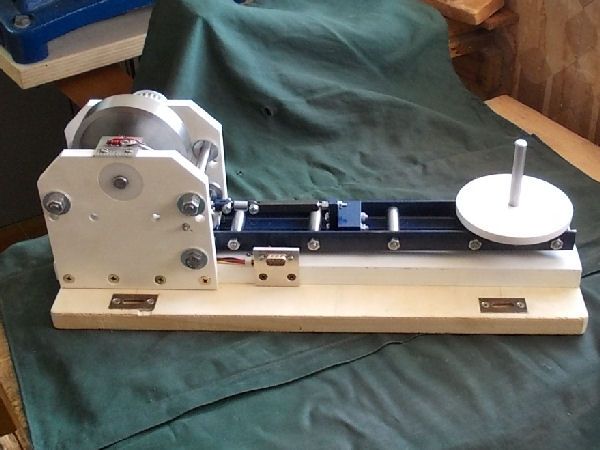
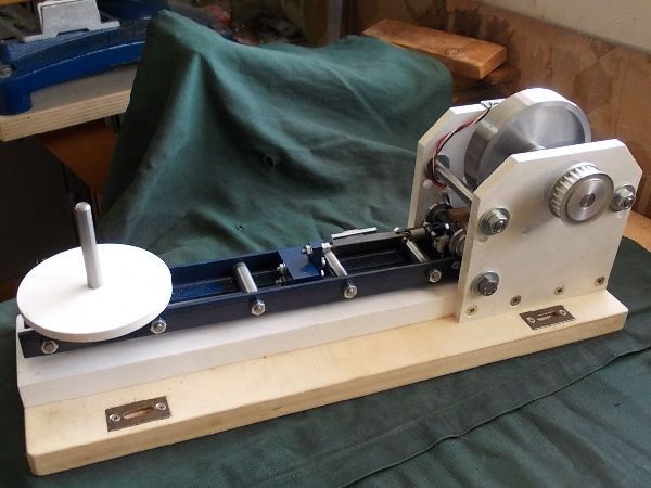
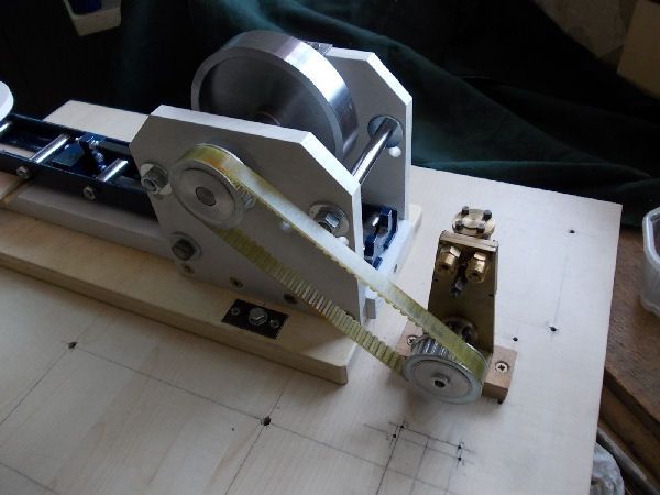
This thread briefly presents an instrument I have developed during the last year to try to measure the delivered power of the small steam engines I have built over the years. I took the basic idea for the instrument from the chapter Testing Model Engines in K.N. Harriss classic Model Stationary and Marine Steam Engines. This idea was the object of a patent by a certain Mr. Sellers in the early 1900s.
PRINCIPLE OF OPERATION
As we know power is defined as energy per unit of time, and energy is defined as force multiplied by distance. In the MKS metric system which I use Time is measured in seconds, Distance in meters, Mass in kilograms, Force in newtons (the force needed to accelerate a mass of 1 Kg at the rate of 1 meter/sec/sec); Pressure in pascals (1 newton per square meter), Energy in joules (the energy needed to move 1 meter against a force of 1 newton) and Power in watts (1 joule per second). At the surface of the earth the force of gravity on a mass of 1 Kg is taken to be 9.81 newtons. Since 1 pascal is a very small pressure, I will use the bar as the unit of pressure. 1 bar is equal to 100,000 pascals and is very nearly equal to one atmosphere.
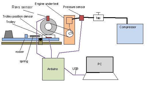
The instrument presented in Harriss book measures power by direct application of the above definitions. The image below, taken from Harriss book, illustrates the principle.
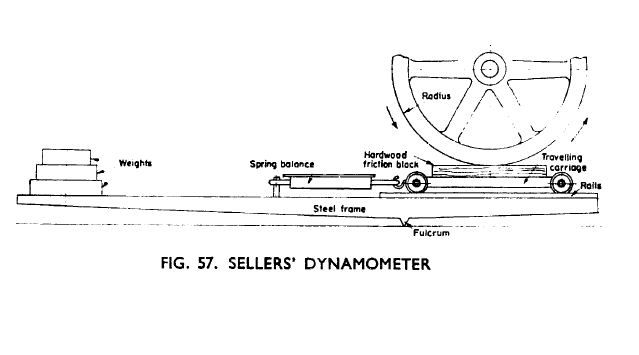
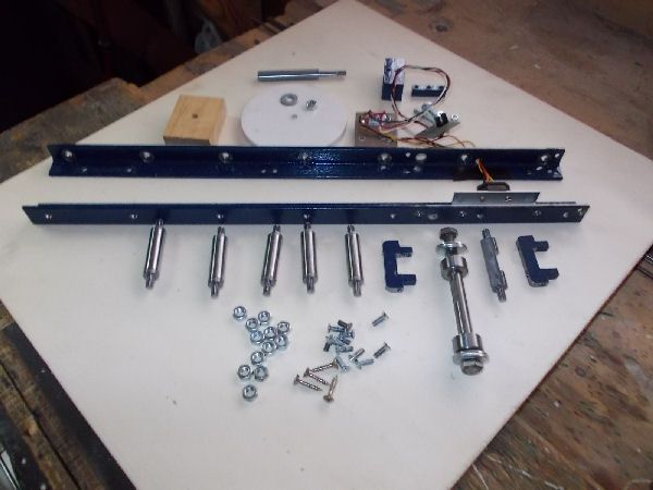
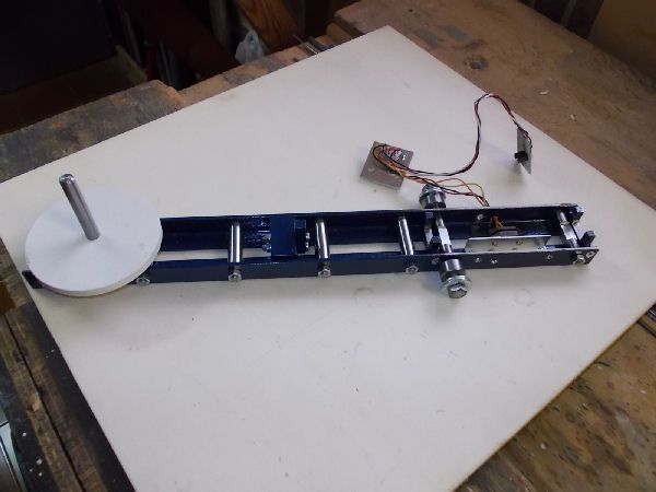
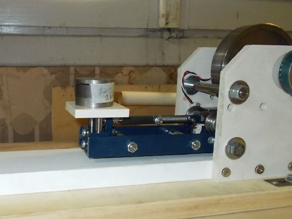
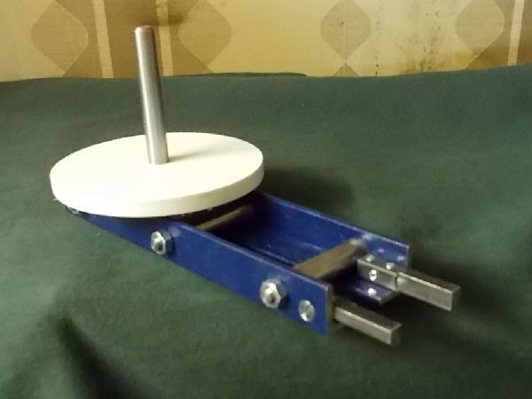
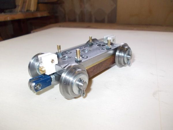
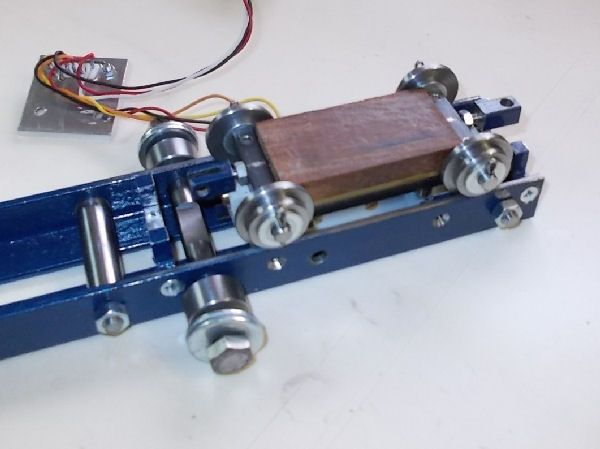
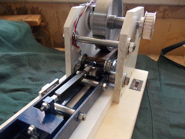
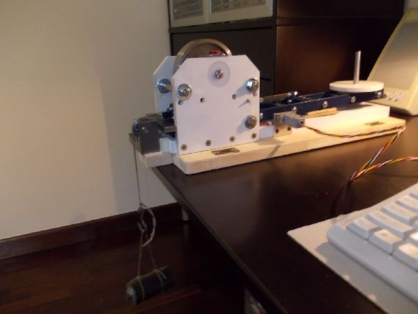
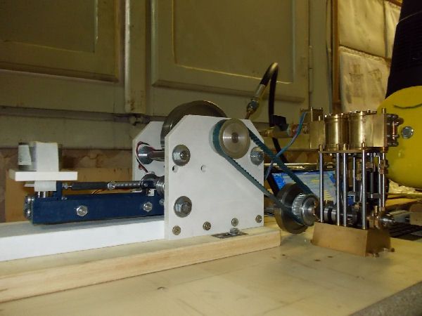
The engine to be measured must drive a brake wheel of the instrument. This wheel is braked by a block of waxed hardwood pressed against its rim. This wooden block is mounted on a trolley which can move along a rail tangent to the wheel rim and which is fixed to the business end of a spring balance. The tangential frictional drag between the wheel and the block is thus directly measured by the spring balance. The rails on which the trolley moves are in turn mounted at one end of a pivoted rocker; on the other end of the rocker is a platform on which weights can be placed to adjust the pressure of the wooden block against the wheel rim.
The spring balance is designed to measure mass by using the earths gravitational force on that mass, so its reading of mass in kilograms must be multiplied by 9.81 to obtain the frictional force in newtons. For each revolution of the wheel the distance moved against this force is simply the length of the wheels circumference. Thus for each revolution of the wheel the energy in joules developed by the engine under test is this force in newtons multiplied by that length in meters. Multiply this energy in joules by the number of revolutions per second and you have the engines delivered power in watts.
Thus to calculate the engines power the instrument must measure two things:
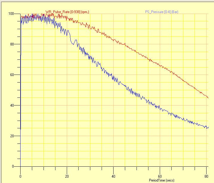
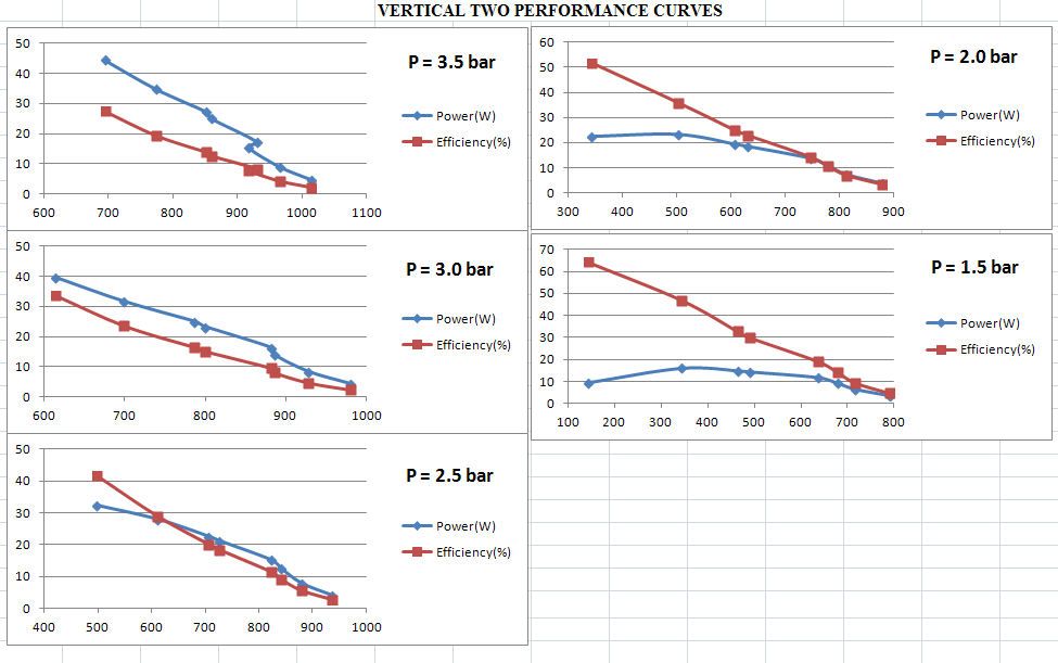
With constant input conditions (pressure, temperature..), one would expect the both the power and the efficiency of a steam engine to be a function of the revs, perhaps presenting a peak at some optimal value of the revs.
ENTER ARDUINO
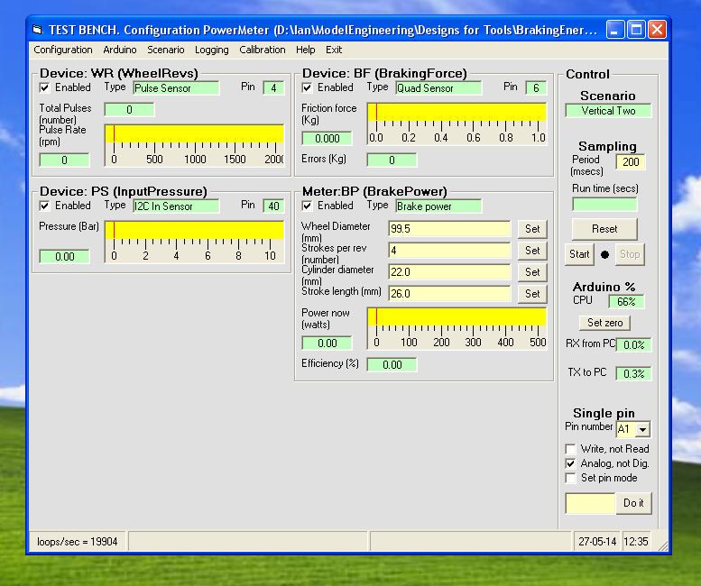
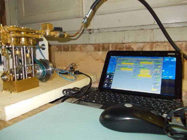
My early attempts to find a means for measuring the revolution rate of a wheel led me to the idea of using an Arduino microprocessor, which actually costs significantly less than a dedicated rev meter and which opens up other fascinating opportunities. So I bought one and took it and my small portable PC with me to play with during my long summer break in the north of Italy away from my workshop. I thoroughly enjoyed this encounter and have become an enthusiastic Arduino fan. The result of my fun is a software tool Test Bench most of which runs on the PC connected via USB to Arduino and which not only measures the revolution rate but can sample and record for subsequent analysis other real time data captured by the Arduino.
An infrared fork sensor costing a few euro (Photologic Slotted Optical Switch OPB626) is used to provide an Arduino digital input with a square wave at the revolution frequency. The axle of the wheel drives a disc with a suitable cutout to allow the infrared beam to pass for only half of each revolution. Arduino measures the time between successive upward transitions and the PC uses this to give a precise rpm estimate of the instantaneous rev rate. I have tested this solution up to over 3000 rpm.
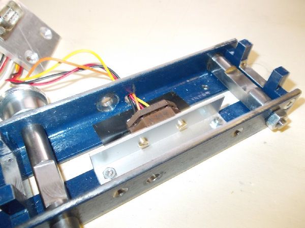
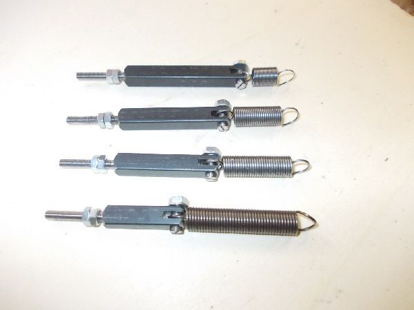
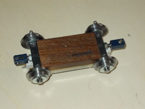
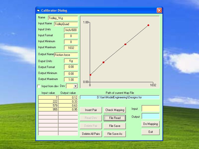
The only spring balance I could find in local shops was for measuring weights up to 10 Kilograms. A few calculations show that a 10 Kilogram frictional force on the rim of a 10 cm wheel is going to dissipate about 30 joules per revolution which, at a speed of 1200 rpm (=20rps) corresponds to a power of 600 watts which is a lot of power for a small engine. And so I decided to replace the spring balance with a precision spring chosen from a set according to the range of power to be measured, and to measure the position of the trolley on which the wooden block is mounted with a linear optical encoder (US Digital EM1 Encoder Module 150 lines/inch), the graduated tape of which is fixed underneath the trolley. Arduino acquires the Quadrature output which reveals motion of the tape through the encoder. A Quadrature signal consists of two digital square waves with a phase difference of +90 or -90 depending on the direction of the motion. The Arduino reveals the transitions on these two signals and maintains an integration counter, which represents the position of the trolley in units of 1/600 inch. The trolley has an excursion of 44mm so the maximum value of the counter is about 1040. Test Bench software on the PC then uses table interpolation to recover the corresponding frictional force in Kilograms. The values in the table, which depend on the spring being used, are defined by a Calibration Process about which more later.
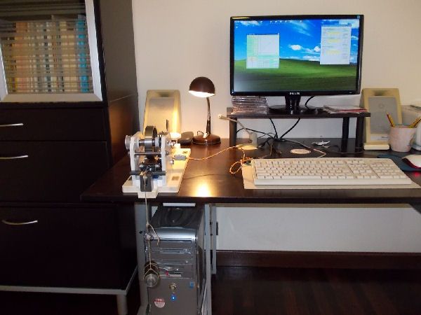
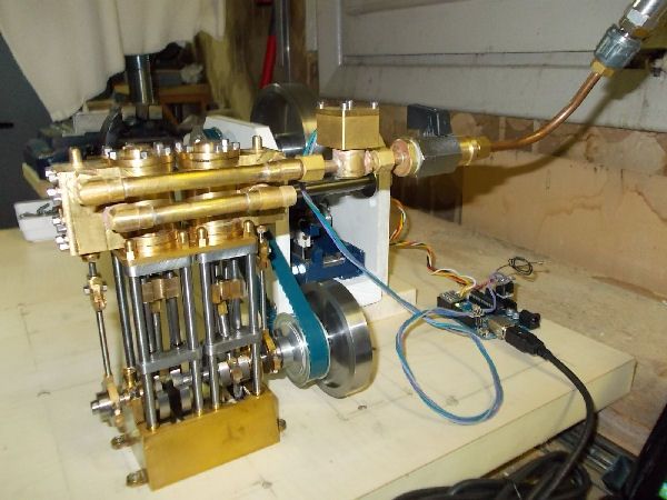
The picture below shows the Arduino with the connecting cable to the instrument.
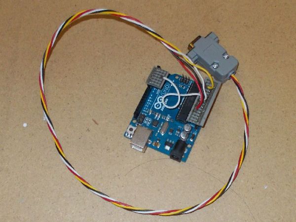
This cable has five wires:
INTRODUCTION
This thread briefly presents an instrument I have developed during the last year to try to measure the delivered power of the small steam engines I have built over the years. I took the basic idea for the instrument from the chapter Testing Model Engines in K.N. Harriss classic Model Stationary and Marine Steam Engines. This idea was the object of a patent by a certain Mr. Sellers in the early 1900s.
PRINCIPLE OF OPERATION
As we know power is defined as energy per unit of time, and energy is defined as force multiplied by distance. In the MKS metric system which I use Time is measured in seconds, Distance in meters, Mass in kilograms, Force in newtons (the force needed to accelerate a mass of 1 Kg at the rate of 1 meter/sec/sec); Pressure in pascals (1 newton per square meter), Energy in joules (the energy needed to move 1 meter against a force of 1 newton) and Power in watts (1 joule per second). At the surface of the earth the force of gravity on a mass of 1 Kg is taken to be 9.81 newtons. Since 1 pascal is a very small pressure, I will use the bar as the unit of pressure. 1 bar is equal to 100,000 pascals and is very nearly equal to one atmosphere.
The instrument presented in Harriss book measures power by direct application of the above definitions. The image below, taken from Harriss book, illustrates the principle.

The engine to be measured must drive a brake wheel of the instrument. This wheel is braked by a block of waxed hardwood pressed against its rim. This wooden block is mounted on a trolley which can move along a rail tangent to the wheel rim and which is fixed to the business end of a spring balance. The tangential frictional drag between the wheel and the block is thus directly measured by the spring balance. The rails on which the trolley moves are in turn mounted at one end of a pivoted rocker; on the other end of the rocker is a platform on which weights can be placed to adjust the pressure of the wooden block against the wheel rim.
The spring balance is designed to measure mass by using the earths gravitational force on that mass, so its reading of mass in kilograms must be multiplied by 9.81 to obtain the frictional force in newtons. For each revolution of the wheel the distance moved against this force is simply the length of the wheels circumference. Thus for each revolution of the wheel the energy in joules developed by the engine under test is this force in newtons multiplied by that length in meters. Multiply this energy in joules by the number of revolutions per second and you have the engines delivered power in watts.
Thus to calculate the engines power the instrument must measure two things:
- the tangential frictional force between the wheel and the block,
- the revolution rate of the wheel.
With constant input conditions (pressure, temperature..), one would expect the both the power and the efficiency of a steam engine to be a function of the revs, perhaps presenting a peak at some optimal value of the revs.
ENTER ARDUINO
My early attempts to find a means for measuring the revolution rate of a wheel led me to the idea of using an Arduino microprocessor, which actually costs significantly less than a dedicated rev meter and which opens up other fascinating opportunities. So I bought one and took it and my small portable PC with me to play with during my long summer break in the north of Italy away from my workshop. I thoroughly enjoyed this encounter and have become an enthusiastic Arduino fan. The result of my fun is a software tool Test Bench most of which runs on the PC connected via USB to Arduino and which not only measures the revolution rate but can sample and record for subsequent analysis other real time data captured by the Arduino.
An infrared fork sensor costing a few euro (Photologic Slotted Optical Switch OPB626) is used to provide an Arduino digital input with a square wave at the revolution frequency. The axle of the wheel drives a disc with a suitable cutout to allow the infrared beam to pass for only half of each revolution. Arduino measures the time between successive upward transitions and the PC uses this to give a precise rpm estimate of the instantaneous rev rate. I have tested this solution up to over 3000 rpm.
The only spring balance I could find in local shops was for measuring weights up to 10 Kilograms. A few calculations show that a 10 Kilogram frictional force on the rim of a 10 cm wheel is going to dissipate about 30 joules per revolution which, at a speed of 1200 rpm (=20rps) corresponds to a power of 600 watts which is a lot of power for a small engine. And so I decided to replace the spring balance with a precision spring chosen from a set according to the range of power to be measured, and to measure the position of the trolley on which the wooden block is mounted with a linear optical encoder (US Digital EM1 Encoder Module 150 lines/inch), the graduated tape of which is fixed underneath the trolley. Arduino acquires the Quadrature output which reveals motion of the tape through the encoder. A Quadrature signal consists of two digital square waves with a phase difference of +90 or -90 depending on the direction of the motion. The Arduino reveals the transitions on these two signals and maintains an integration counter, which represents the position of the trolley in units of 1/600 inch. The trolley has an excursion of 44mm so the maximum value of the counter is about 1040. Test Bench software on the PC then uses table interpolation to recover the corresponding frictional force in Kilograms. The values in the table, which depend on the spring being used, are defined by a Calibration Process about which more later.
The picture below shows the Arduino with the connecting cable to the instrument.

This cable has five wires:
- 0V (black)
- +5V (red)
- Square wave from infrared fork sensor for wheel revolutions (white)
- Square wave A from linear encoder for trolley position (orange)
- Square wave B from linear encoder for trolley position (yellow)


