Finger Engine Clutch"

Home Model Engine Machinist Forum

Help Support Home Model Engine Machinist Forum:

This site may earn a commission from merchant affiliate links, including eBay, Amazon, and others.

Captain Jerry

Project of the Month Winner!!!
Project of the Month Winner
Joined
Dec 2, 2008
Messages
971
Reaction score
8
Hi All!

This is an offshoot from an older thread from 2008 that got revived because of a more current thread about finger engines. I thought it more appropriate to start a new thread because it has taken a different course. The parent thread can be found at
http://www.homemodelenginemachinist.com/index.php?topic=2063

It is worth the time to take a moment to read that thread if you haven't already.

This thread is aimed at building a finger engine that uses a clutch or other method to decouple the finger treadle from the flywheel so that the flywheel will continue to freewheel after treadle action stops.

There have been a few ideas and suggestions offered. So far only Arnold and I have jumped in, but there is plenty of room for everybody. The rules are simple. The above paragraph is all there is.

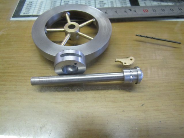
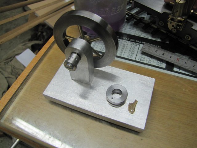
Arnold thought that he would get some shop time on it today and so did I. My shop time was spent mostly looking through the pile of discarded parts from other projects. I found what I was looking for and cobbled up a mock up as shown here:

fingerandrevvalve002.jpg


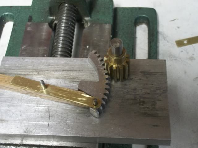
It make take some imagination to understand. Imagine that the small pinion is on a shaft with a flywheel. When the free end of the treadle is depressed with a finger, the gear segment pivots on its bottom pivot pin and is forced into mesh with the pinion and drive it clockwise. At the end of the power stroke, the gear segment pivots out of mesh with the pinion and is returned to the lower position by a spring. The process repeats.

fingerandrevvalve004.jpg


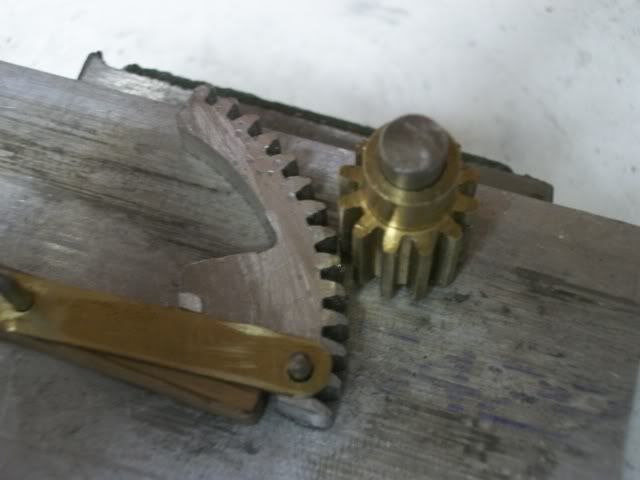
Position, clearances, springs, stops have still to be worked out, but that for tomorrow ( or later)

Arnold, how did you make out?

Jerry
 
Jerry, I played around with the spring clutch idea - it will work but as Noitoen said the friction will slow the flywheel down pretty quickly.

A roller clutch (balls can do as well for low torque) would work - consists of an outer hub with the surface rad inclined by 2° at three points forming 3 "wedges" when turned in the one direction the rollers (balls) move to the open end of the "wedge" when turned the other way they lock into the wedge.

No springs required as gravity will drop at least one roller into the wedge.

A fiddly bit of work for the rotab.

Ken

clutch.JPG
 
Nice going Jerry Thm:

Ken, that's one of the solutions I looked at. I settled on a slightly different method though - just need some time in the shop to build it.

:big: What was supposed to be a quiet weekend for me turned into a social fest with a steady stream of visitors and partying; I didn't even get to unlock the shop, never mind build anything.

Regards, Arnold
 
I remember when I was a kid, once I saw an artisan turn some wood souvenirs with a "man powered" wood lathe. The lathe structure was very crude, mounted under a tree. A flexible branch of the tree acted as a spring with a piece of rope tied to it hanging above the lathe's shaft, went once or twice around the shaft and the other end of the rope was tied to a wood plank that acted as a pedal. When he pressed the plank it would spin the shaft and as he released the pressure the "branch spring" would pull the pedal back up and let the shaft spinning due to a small flywheel.

Here is another version http://www.wood-lathe.org/articles/a-brief-history-of-wood-lathes
 
I am unable physically to join in the fun on this little project, but that doesn't stop me thinking about ways to get the drive from the finger treadle to the flywheel gears.

I don't know if anyone can understand this C-o-C, but with a little bit of fiddling, this should be able to be got to work. Maybe a second spring would be required under the finger button to allow it to retract a little quicker. The only problem I can forsee is getting too much pressure produced between the taper and cone. That could be solved by having the fixed taper that the shaft taper runs against to be slightly spring loaded, or even an o-ring in a recess instead of the internal cone against the taper.

There are most probably hundreds of ways of solving this problem, so even if you aren't going to make one, how about knocking up a C-o-C to give your ideas to the subject.


John

Treadle drive.jpg
 
dmac

Sure a one way bearing would work but that's so easy, it was the one solution that was ruled out. For the purpose of this discussion, project, or brainstorming session, the clutch mechanism must be shop made.

There have been some good ideas proposed and the way I see it, all of them could be made to work. There is no time limit on this project so if something pops into your head, tomorrow, next week, next month, build it, draw it, model it, or just describe it.

One of the things that I have been wrestling with is the fact that a finger engine treadle operates over an arc of no more than about 20 degrees. So the clutch must actuate in a small fraction of that if there is going to be any arc left to provide power, and it must disengage cleanly without robbing any energy from the flywheel. Lots to think about.

Another idea hit me this afternoon and you have probably seen it in music boxes and wind-up toys of all kinds. It uses a drop out pinion between the driving gear (attached to the finger treadle) and the driven gear (attached to the flywheel). The pinion is fixed on a short axle shaft that moves in a short slot that keeps in mesh with the driving gear. When the shaft is at one end of the slot, the drop out pinion is also in mesh with the driven gear. When the driving gear stops or reverses, the pinion is pushed to the other end of the slot, un-meshing with the driven gear and letting it freewheel. That should be easy to build. If I had another pinion laying around, I would give it a try.

Jerry

Jerry
 
I just thought of another mechanism. Those "pull-back and release" toy cars have a sort of multiplication system that gets the car to run fast and far with a little pull-back movement. Should investigate how it works ;)
 
Here is a quick sketch of the drop out pinion. The finger pedal would be directly attached to the large gear on the right.

Jerry

Drop out pinion.JPG
 
Jerry,
If you made the top of the pinion teeth pointed instead of the usual flats. The posibility of the flats hitting when they rengaged would be elimated which was the problem I was having thinking about a gear design.

I like that one.

Dan
 
Dan

I think you are right about that. The two gears meshed and ran well when the centers were at the correct distance. They got a little rough when I cut the drive gear quadrant and drive it into and out of mesh. I took a file to both gears and eased the corners off of the teeth and the action is much better. Thanks for the suggestion.

Jerry
 
;D I finally managed to get 5 hours in the shop today...

Built some crude bits from odds 'n ends lying around:
normal_IMG_2816.JPG


And a base:
normal_IMG_2817.JPG


I tried to do a ratchet drive that will use the inertia of the "crank" movement to engage the ratchet, and once it goes beyond a certain point will automatically disengage. A spring below the "finger" (not built yet) will pull back things for another stroke. Things don't quite work like I wanted it to though - it only half-works which is no good for me.
There is too much friction between the outer ring and the inner "drive" bit with the ratchet on, and it is a bit too light as well as it's made from aluminium , so it does not provide enough inertial resistance to properly engage the ratchet. The ratchet mechanism is a wee bit shallow as well, so it's back to ye olde papyrus and pen for those bits.
;D Already have a plan; just need a bit more shop time.

Kind regards, Arnold
 
Looks great Arnold!!!

Just making the flywheel would take me forever!!!!

Andrew
 
If I could give you a clue to getting it to work correctly.

Have your treadle driving a fairly large gear rather than direct to the flywheel, then the large gear driving a smaller gear connected to the flywheel.

Doing it that way, most of the energy you produce from the very short stroke of your clutch will be driving the flywheel a little faster each time and so storing that small amount of energy you are able to produce each stroke.

That is the way Bill Reichart managed to get his to run.

Without that addition, I don't think you can generate enough flywheel momentum to keep things going, unless you can say extend the drive treadle driving part to give a lot more than just a part of one revolution to the flywheel.

As I stated when we first discussed this on the other link, I had already looked at different methods of clutch to see if the gears could be done away with. But when you study the original plans in detail, you can see why the gears need to be in there, and I think the exercise was only to come up with a new clutch system rather than the roller variety.

I hope you can understand my ramblings.


John
 
Bogs

Your ramblings make perfect sense. I may be slow but I'm heading in that direction. The planets may revolve about the sun many times before I'm finished.

Jerry
 
Would something like a bendix gear work?

Is that essentially what you're already doing there?

(please excuse my noobishness)

Is that also the kind of gear that allows your feet to stay stationary when you're coasting on your bike?

Just trying to understand if a modification of that sort of assembly may work.
Or... if not, why not?

:)
 
checkedout said:
Would something like a bendix gear work?

Is that essentially what you're already doing there?

(please excuse my noobishness)

Is that also the kind of gear that allows your feet to stay stationary when you're coasting on your bike?

Just trying to understand if a modification of that sort of assembly may work.
Or... if not, why not?

:)

Checkedout

I don't know how the bicycle coaster brake works but in principle it seems like the same thing. The bendix uses a helix to drive the starter pinion into mesh with the flywheel gear. I think the problem with that is that the helix has to make one or more revolution to engage.

As I see it, finger engine treadle makes less that a 1/4 revolution per stroke and the clutch mechanism must engage in a ver small fraction of that stroke. It must also disengage completely and instantly at the end of the stroke.

Bogs

I understand that gearing would allow the small input arc to transfer more energy to the flywheel. Would a LARGE flywheel give the same action. More inertial resistance to absorb more energy on the short stroke?

Jerry
 
While thinking about all of the possible ways to make a one way clutch I kept avoiding the most direct approach. Instead of gears, wrapped strings or springs, how about just a clutch? You know, one thing rubbing against another thing. I drew up an Alibre' model Tuesday night, made some parts Wednesday, and fiddled with it today. I didn't really get it finished but I got close enough to do a trial assembly and test. There is no base, and no return spring, the flywheel is my plumbing parts baton and there are some minor revisions to be made but it works surprisingly well.

I didn't get any build photos and only a couple of videos of the trial. Here it is:

[ame]http://www.youtube.com/watch?v=o-LvTNnPeg8[/ame]

I haven't decided on the final mounting but I will work on it tomorrow. I will take it appart and try to get some pics of the works.

Jerry
 
That is a really cool design Jerry!!!
Works a treat too!!

With a return spring and a stop to position the lever in a handy place it will be perfect!!!

Seeing how the clutch works would be great!!!!

Excellent work!!!! :bow:

Andrew
 
Back
Top