exp. design for a dbl. acting mini. hydraulic cylinder

Home Model Engine Machinist Forum

Help Support Home Model Engine Machinist Forum:

This site may earn a commission from merchant affiliate links, including eBay, Amazon, and others.
Hi Kel.

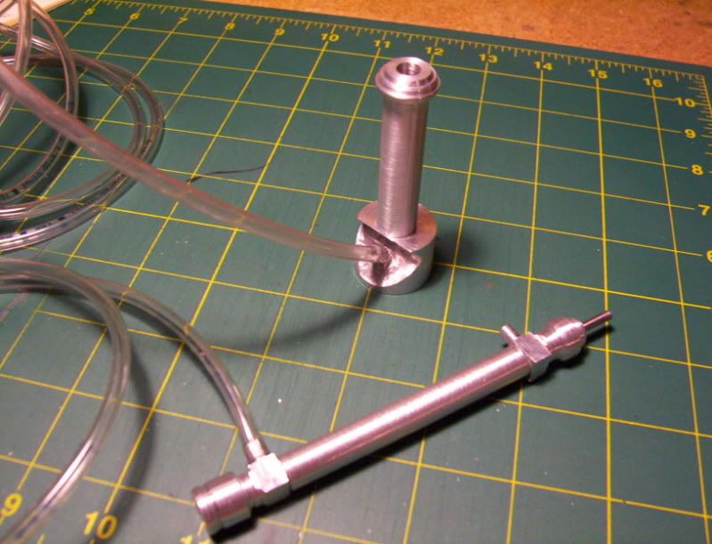
At the moment, I'm using the plastic tubing, pretty much the kind for fish aquariums, air tubing.

That's the kind of tubing I used for my lift table, I don't recall having any kind of issues with that table project using that tubing, If it was expanding and causing problems I really didn't notice anything, however your RC projects may need more precision in its movement of the piston, while my table project was more like brute force just to get it to raise up.

Have you tried "smallparts.com", they may have the kind of lines your looking for.

Thanks for watching my thread.


Hello to everyone,
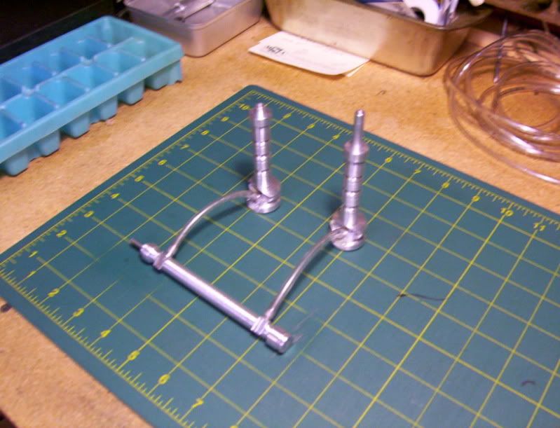
Update in my build thread:

As I said in my earliewr posts, my work in progress threads go from one idea of build to a completely different approach until I hit the right combination.

I hope this thread isn't becoming confusing, with all the detours I take.

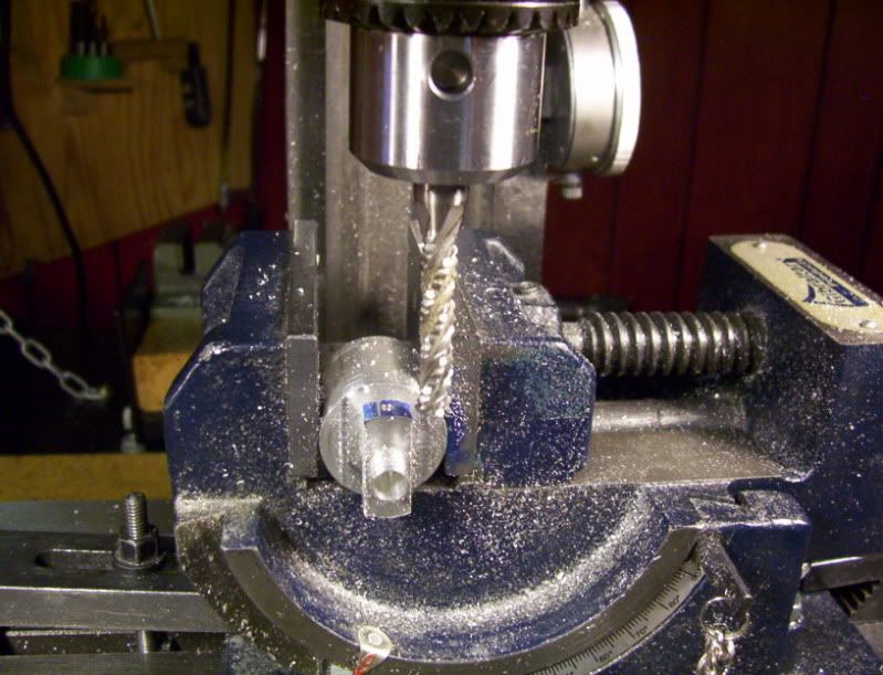
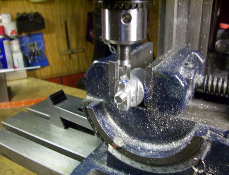
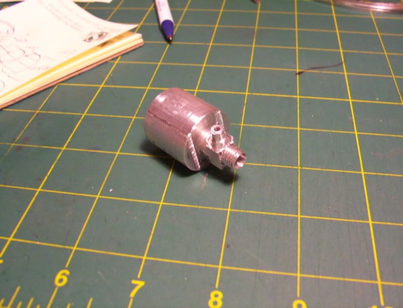
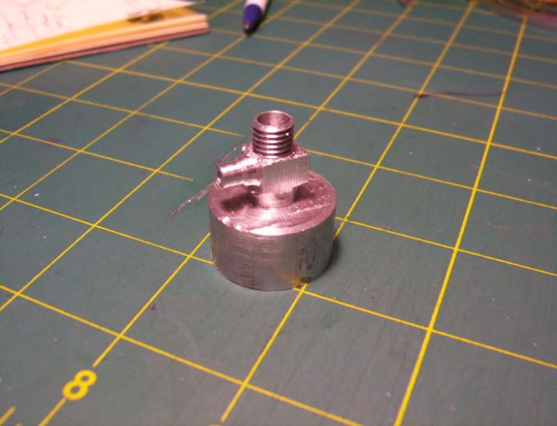
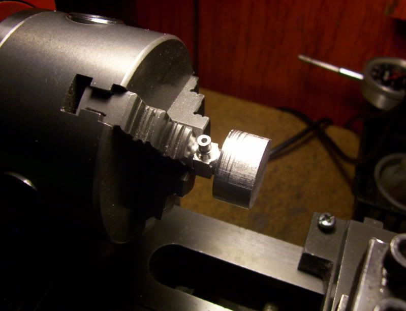
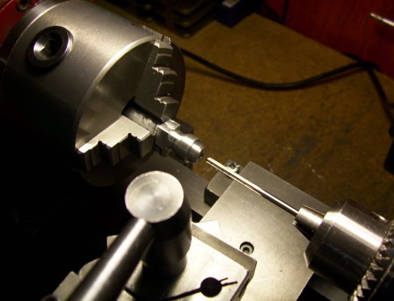
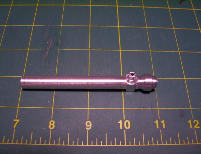
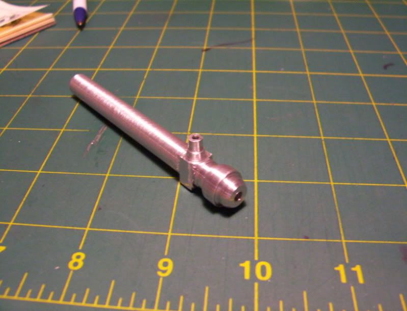
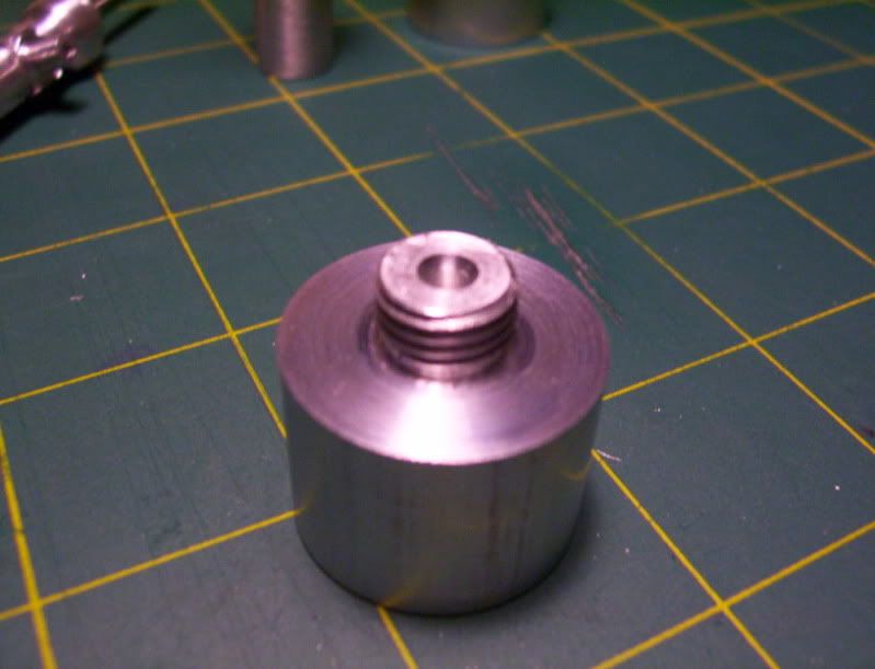
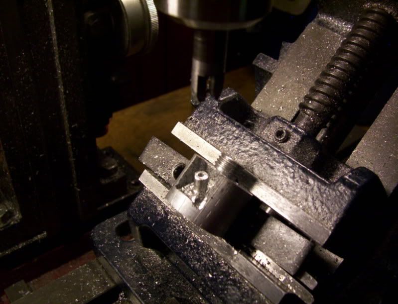
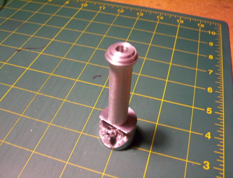
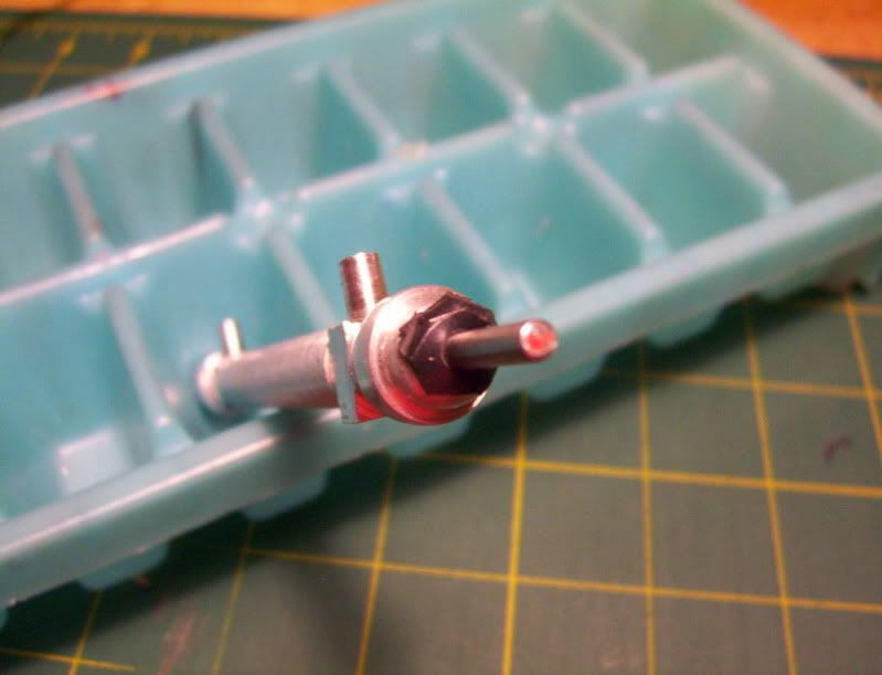
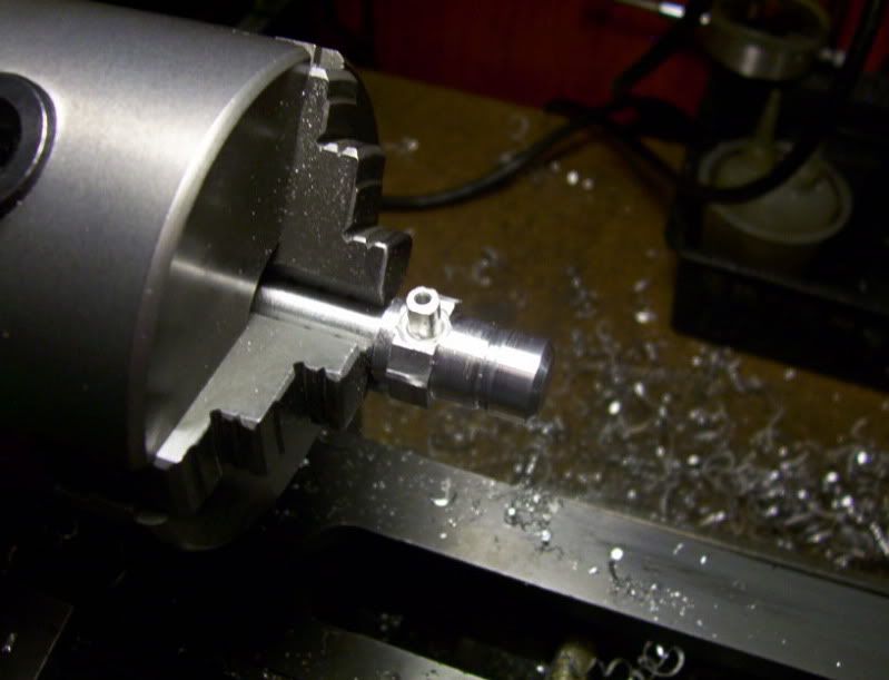
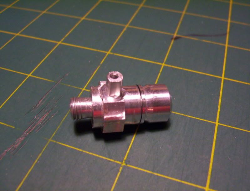
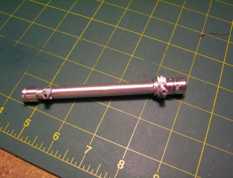
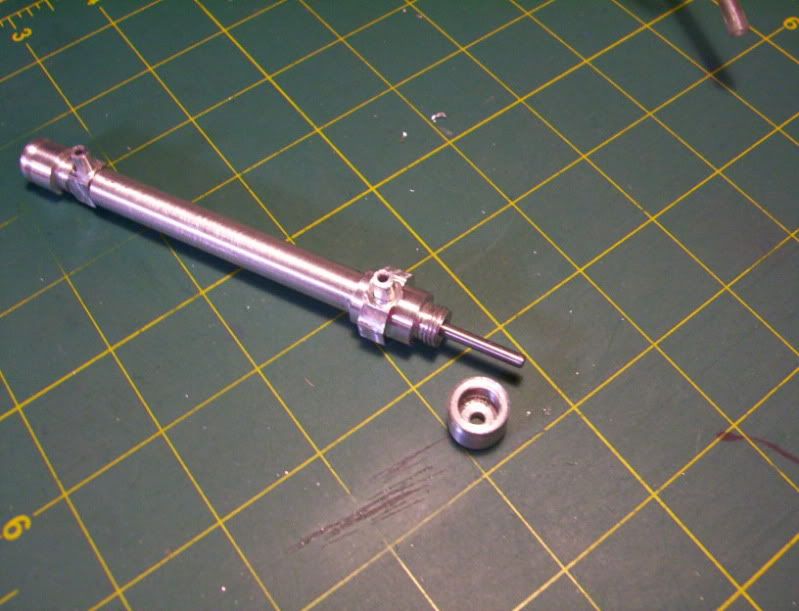
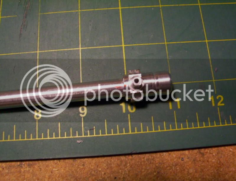
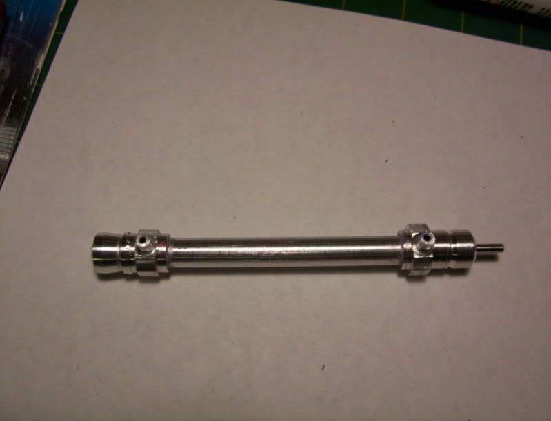
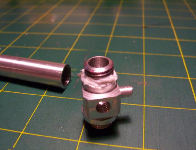
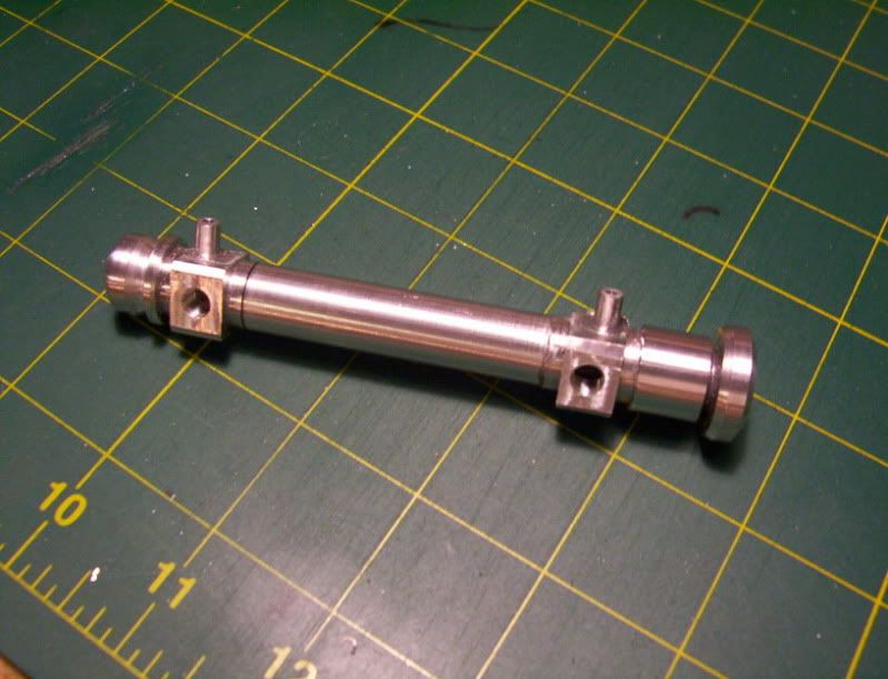
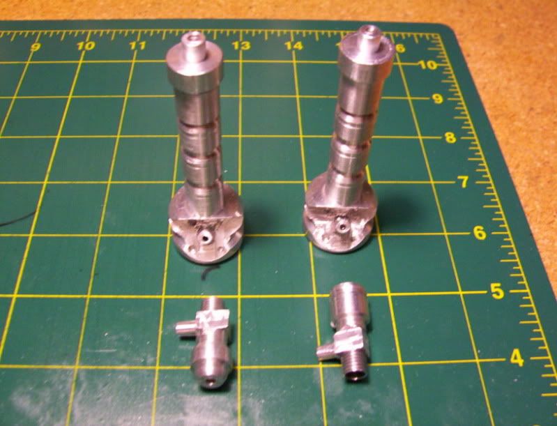
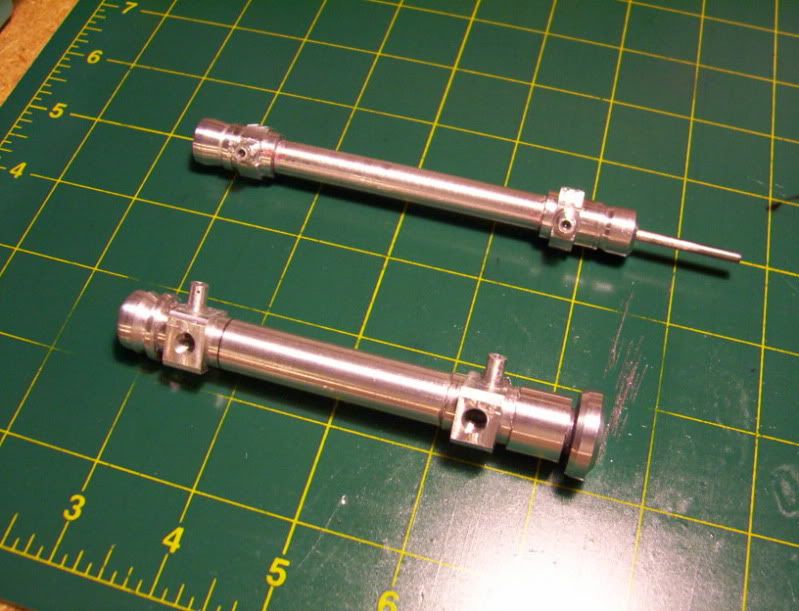
With that said, I am now REDOING AGAIN the whole cylinder arrangement, the reason for that is, when I did my last cylinder, it came out great, However I clamped the cylinder after it was hollowed out just a little too tightly in my V block to machine the tube connector, and put a dent on the inside that will not ream out, the piston stilol works fine, but now and then there is a small catch in that area.

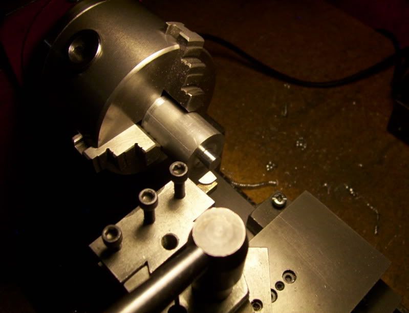
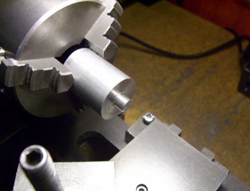
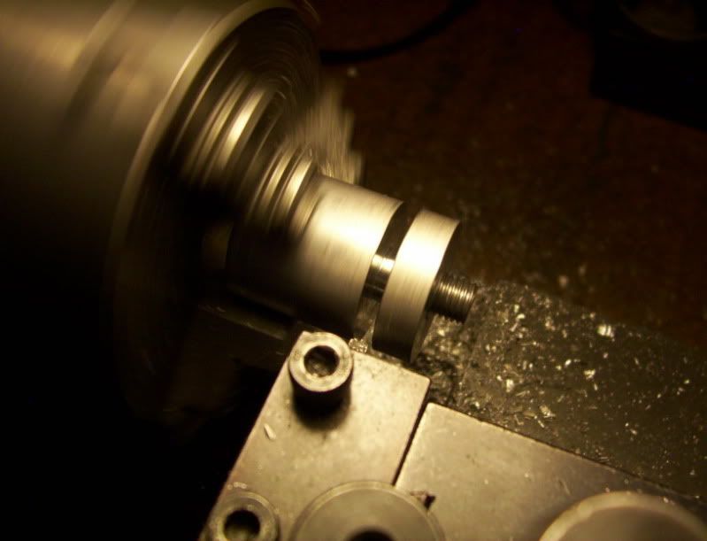
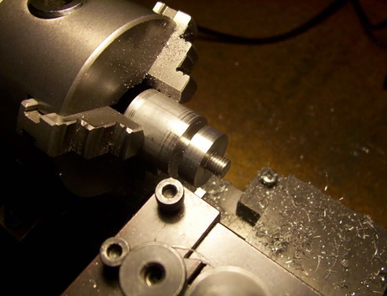
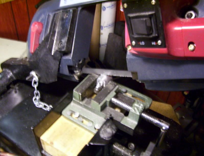
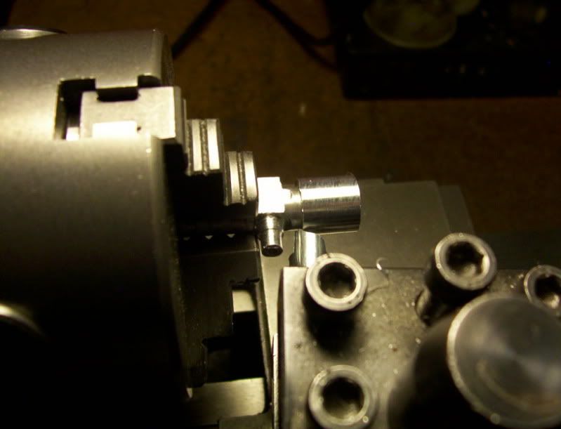
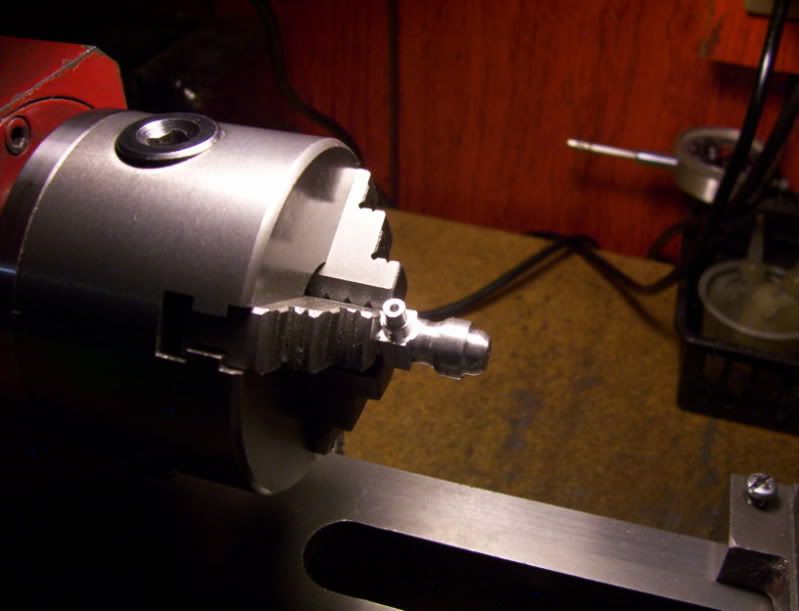
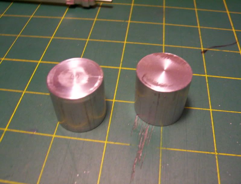
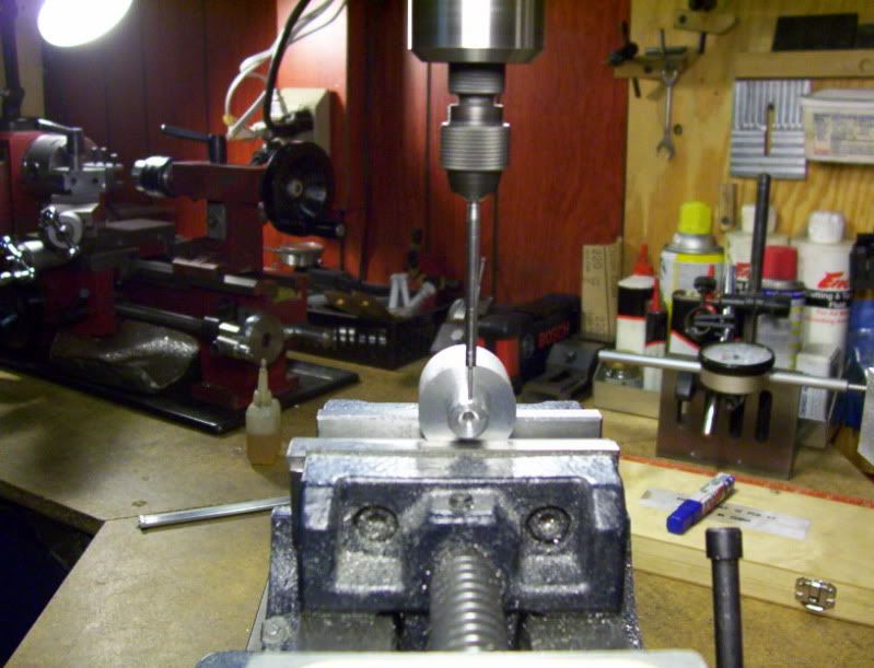
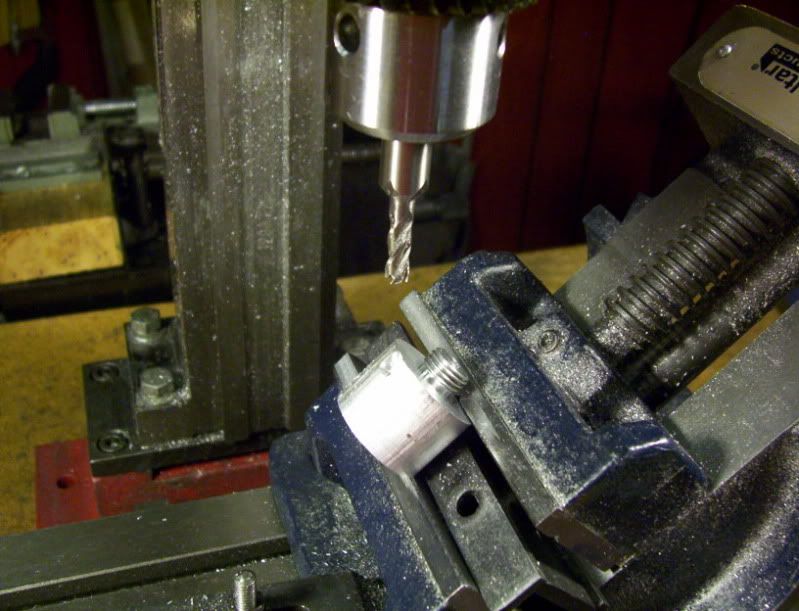
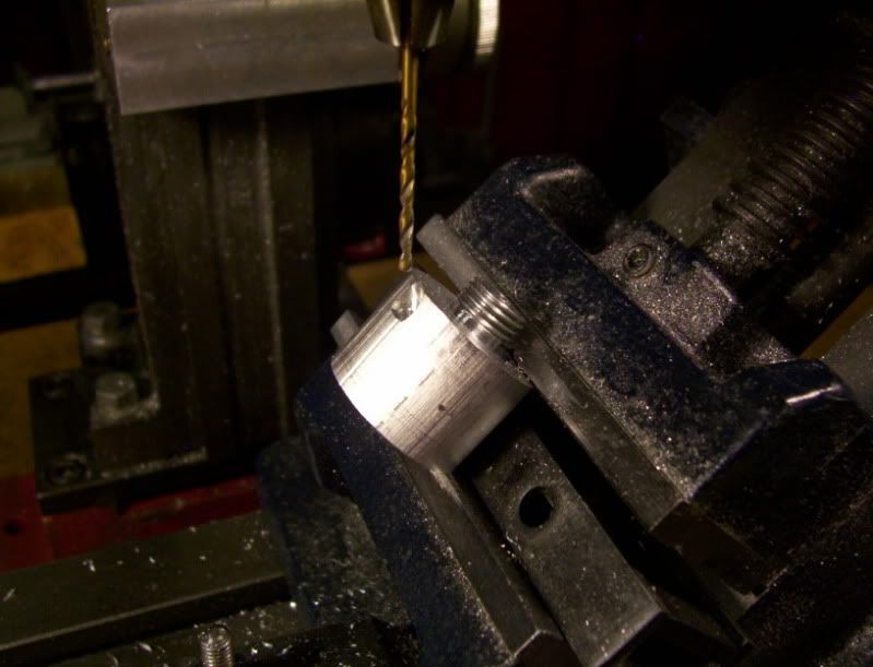
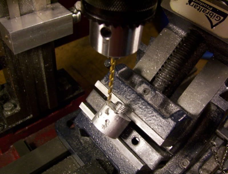
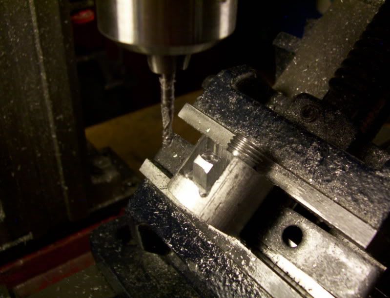
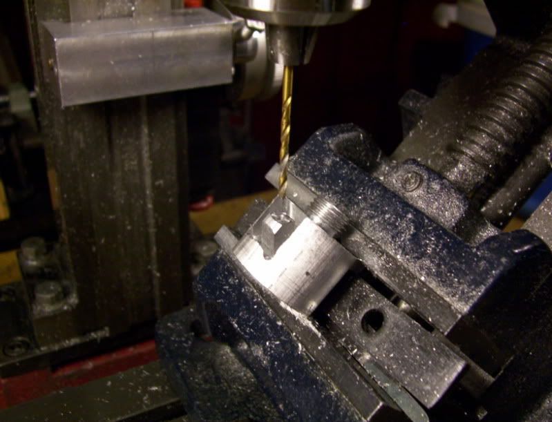
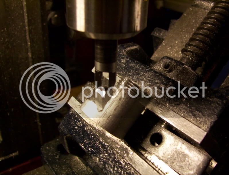
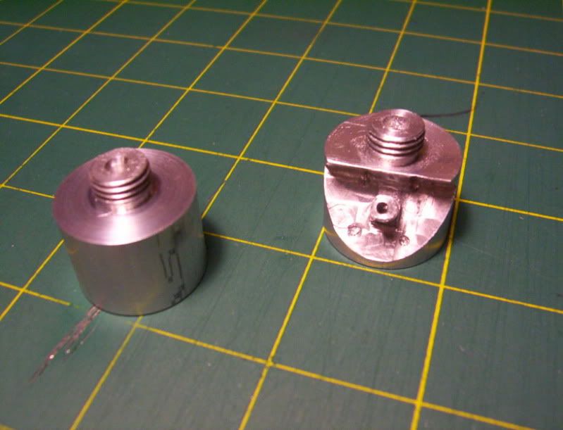
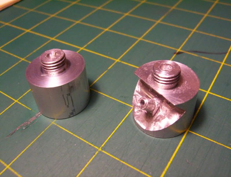
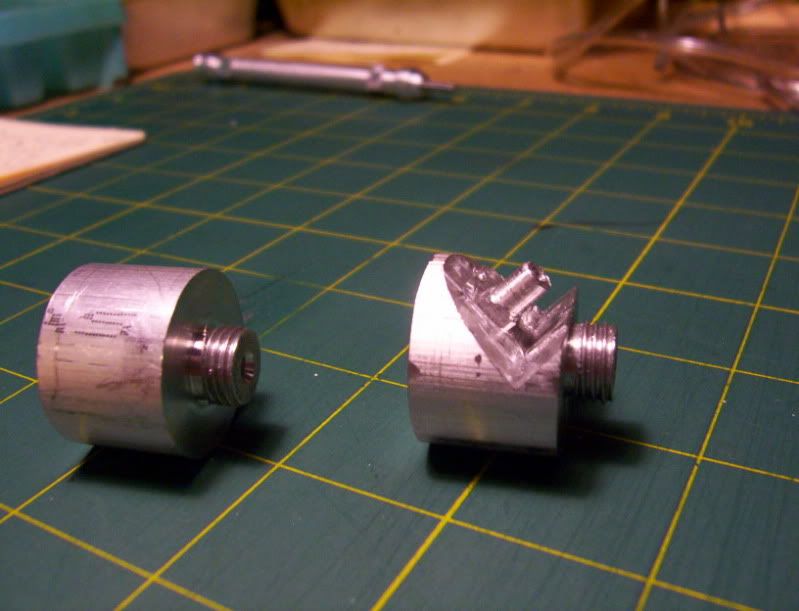
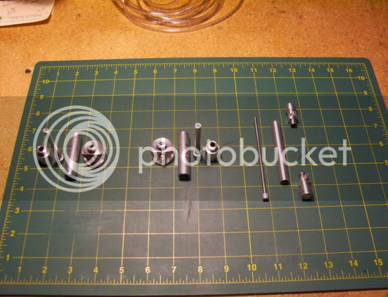
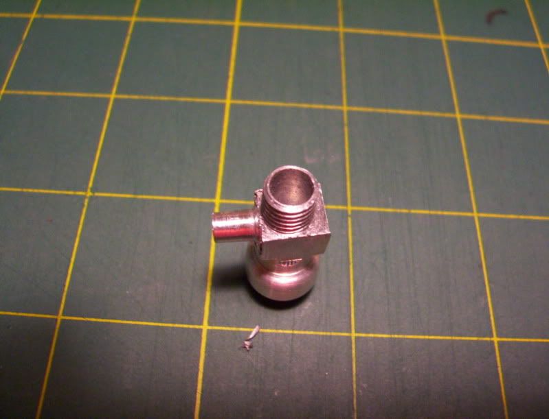
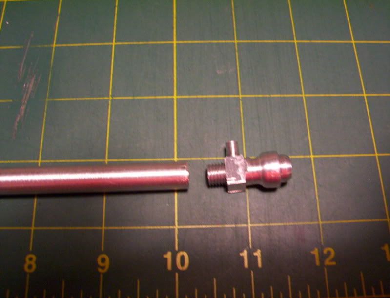
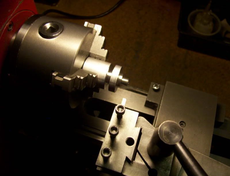
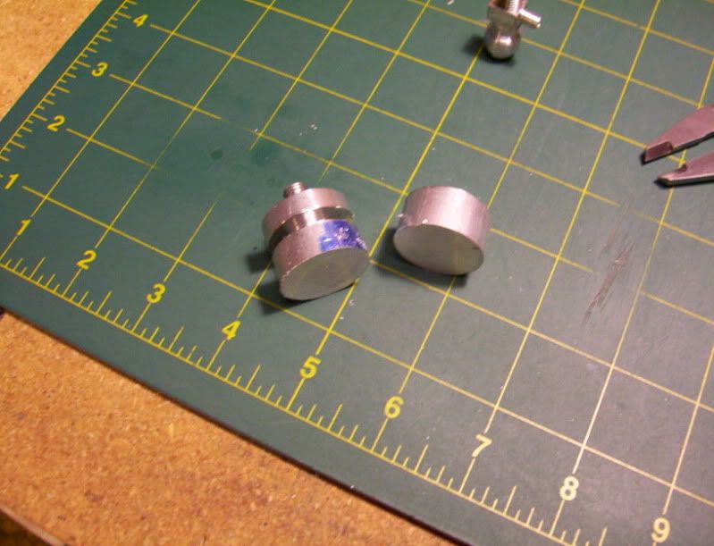
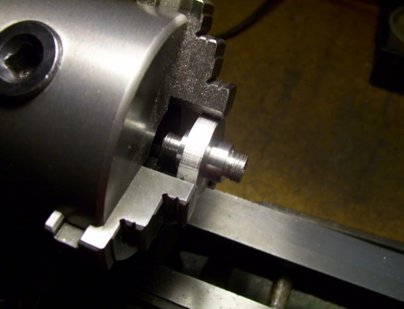
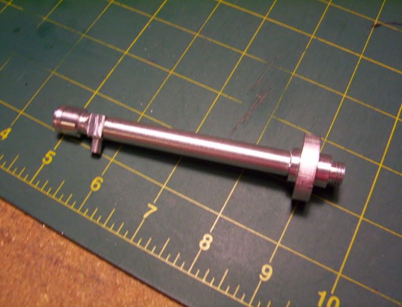
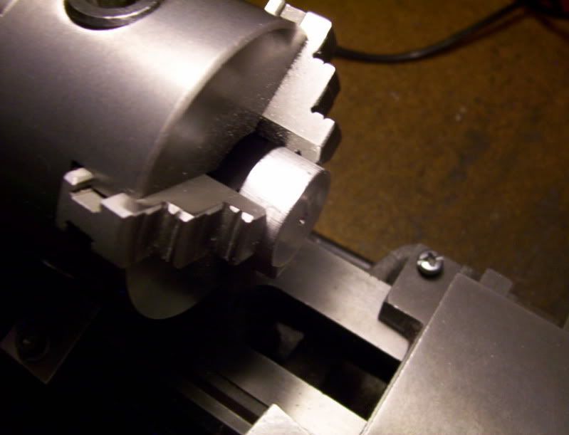
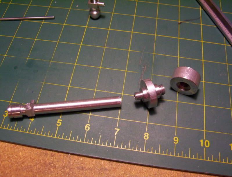
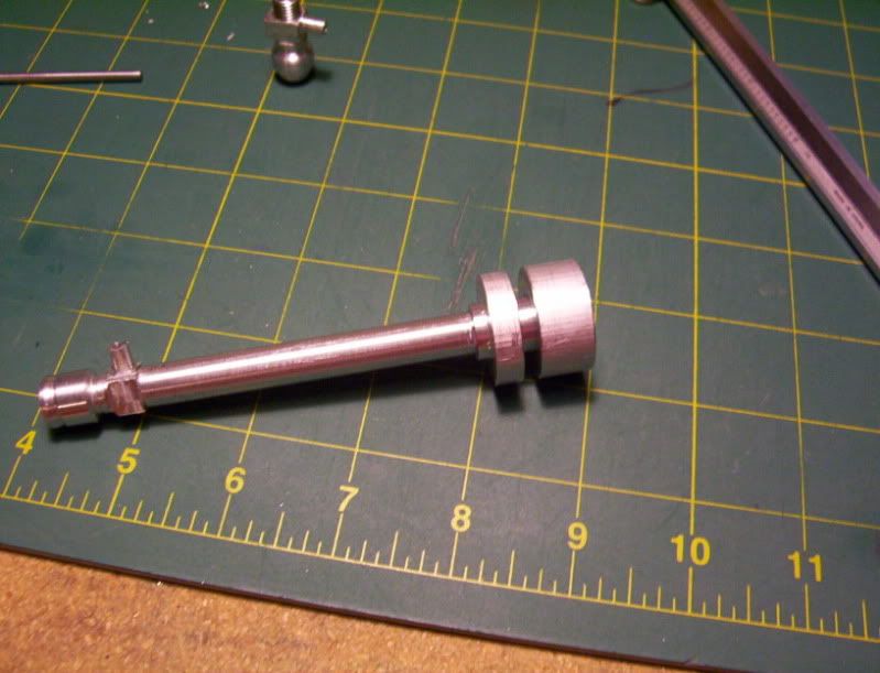
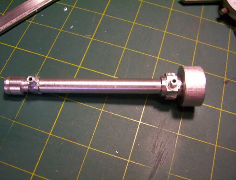
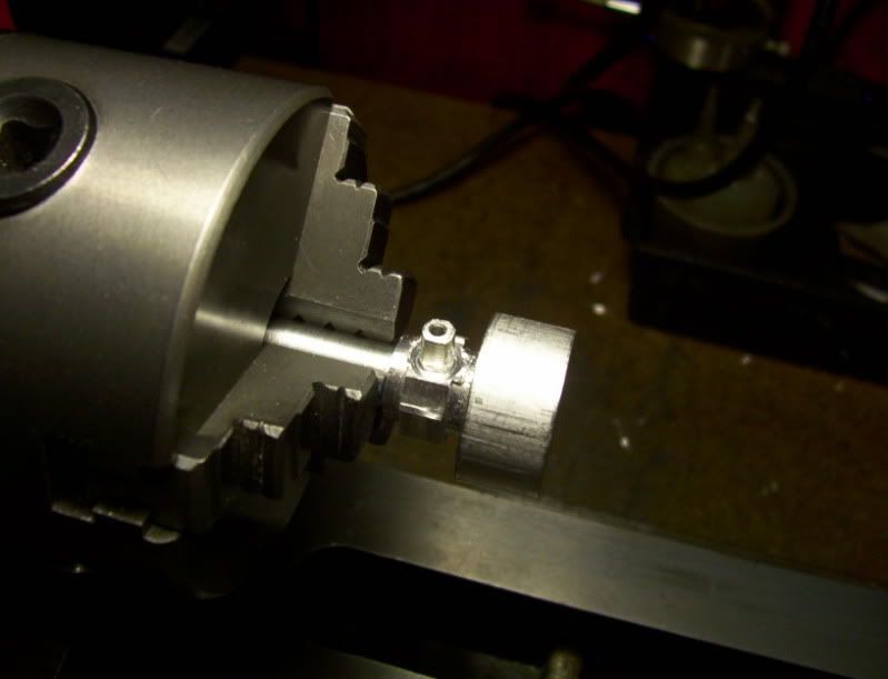
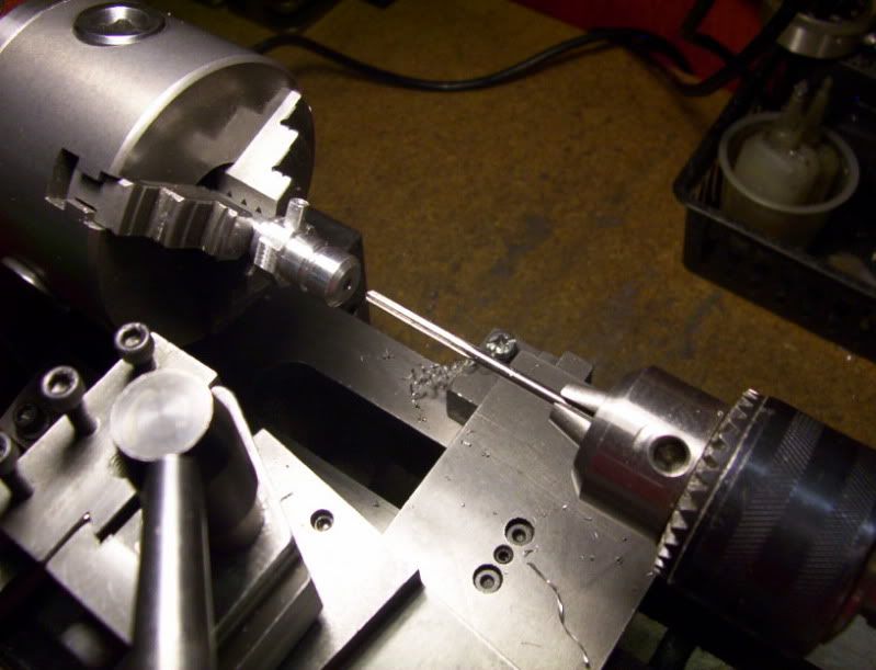
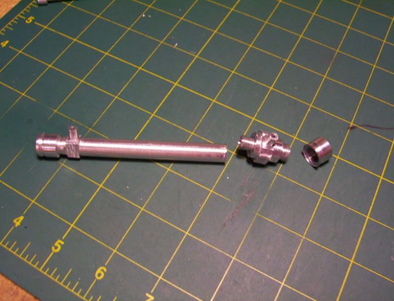
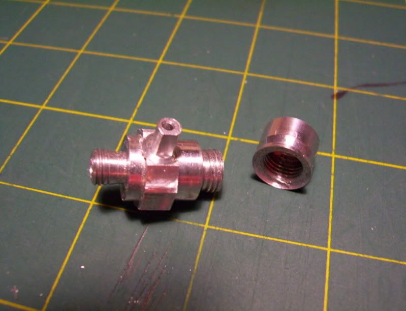
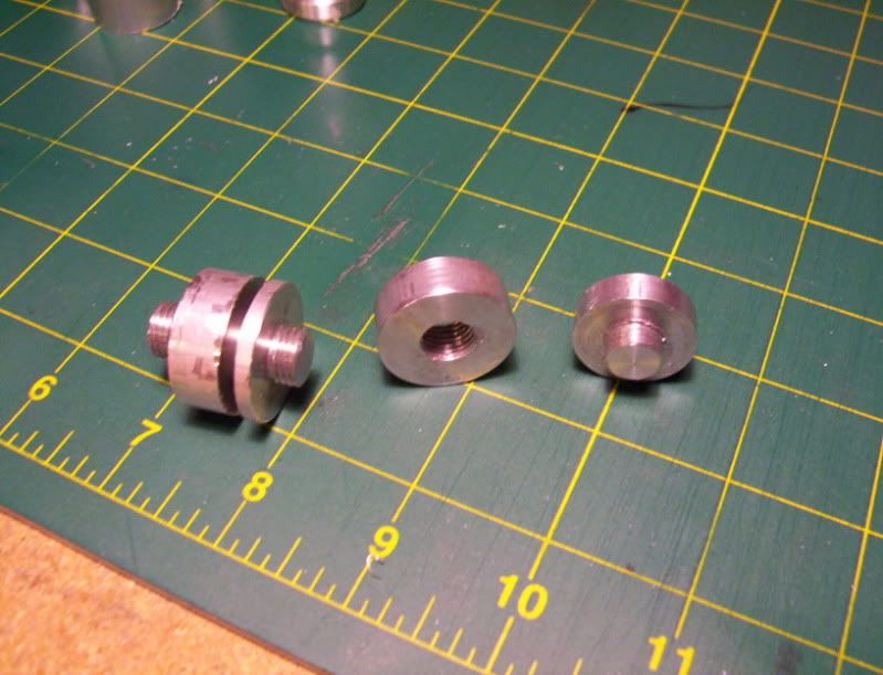
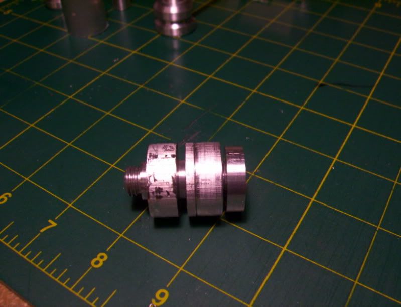
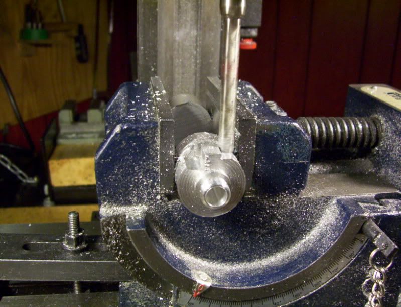
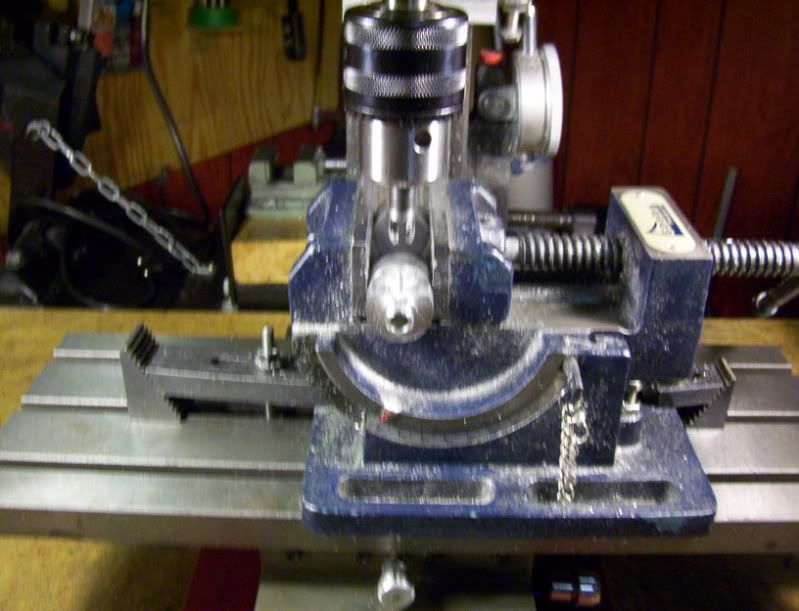
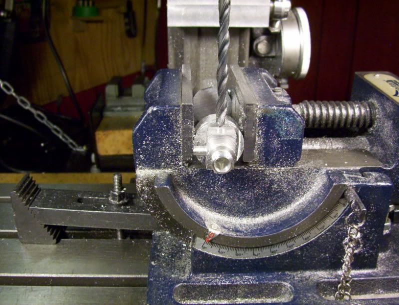
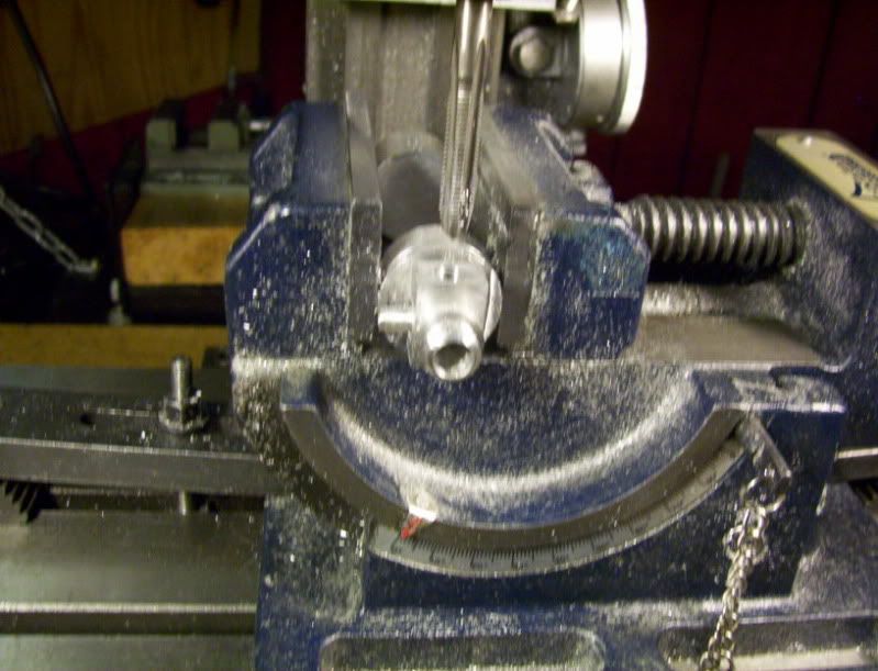
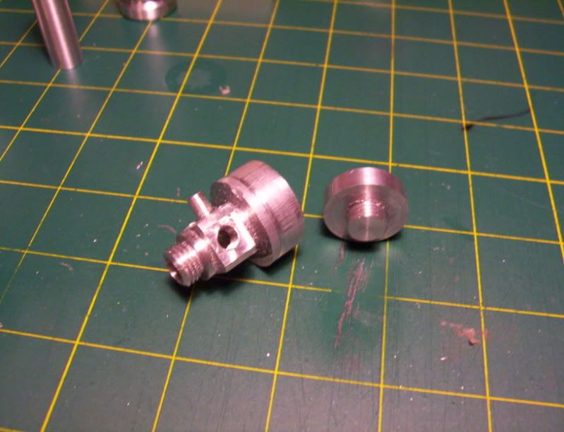
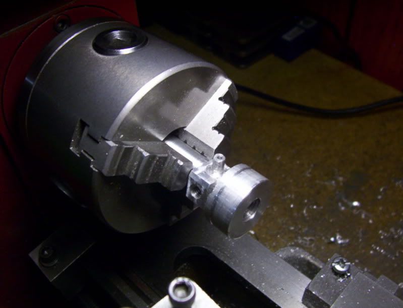
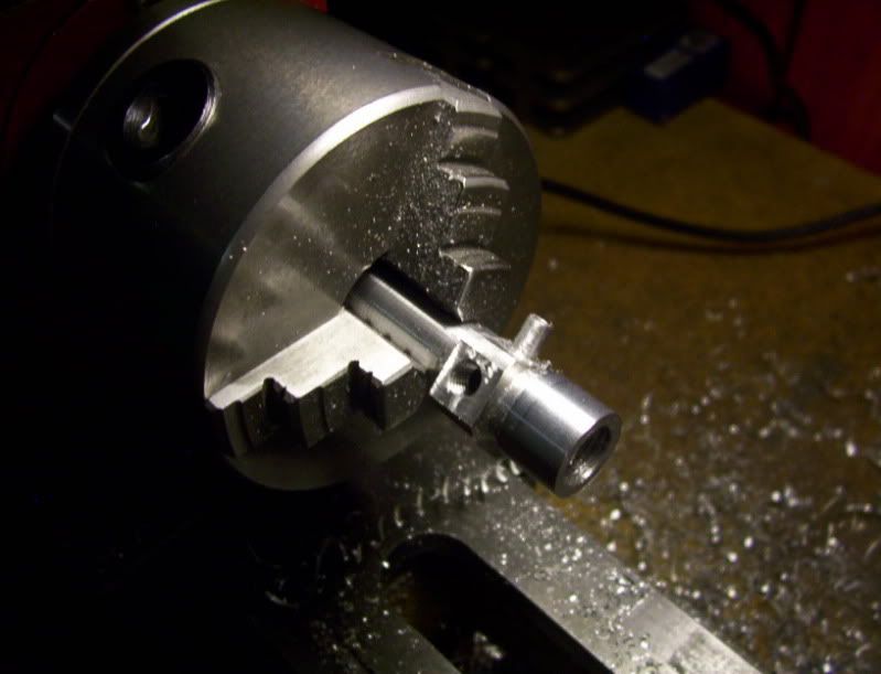
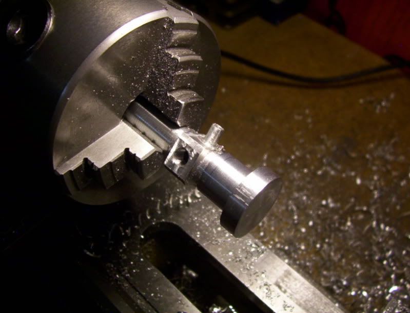
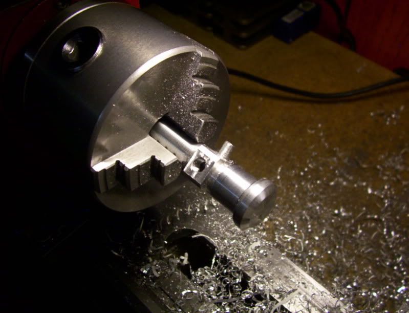
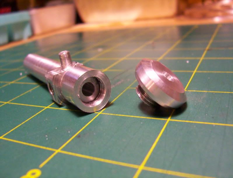
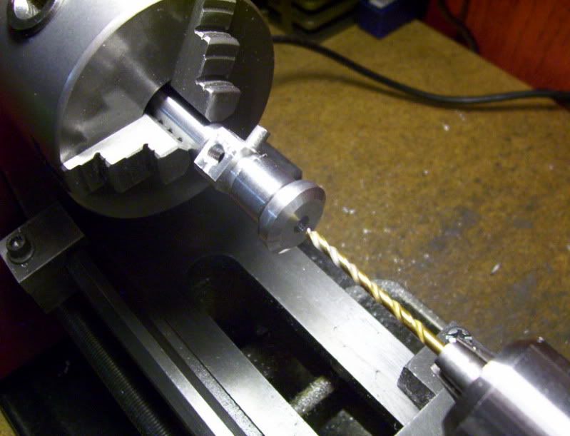
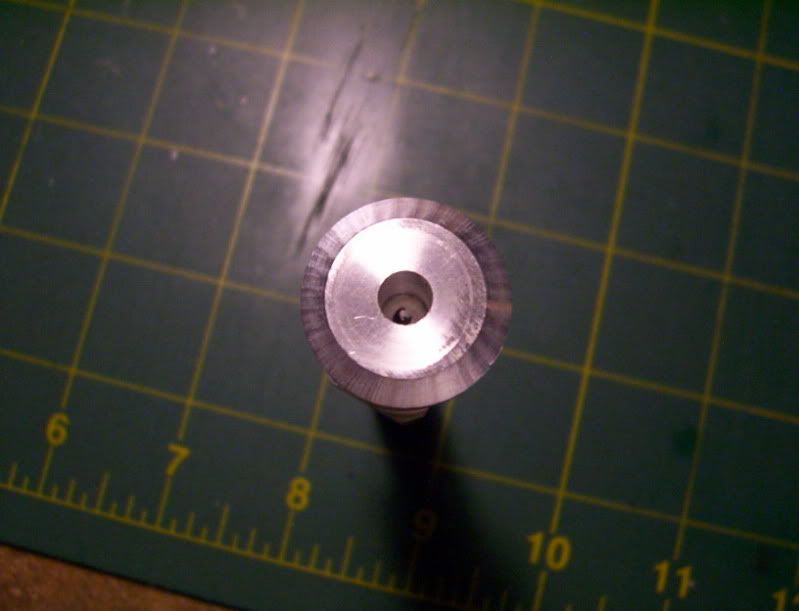
But as I was thinking about the best way to build these should I want to build several, I thought about using 3/8" dia. alu. rod, for the cylinder, and machining as one piece the tube connectors onto the end caps, that way less iterupted cutting on my lathe for the length of the cylinder, and use 3/4, to 7/8 dia. rod for the endcaps, with no offsetting in the lathe but all machining would be done on the mill for the tubeconnectors.

These are ideas I'm kicking around right now.
 
To make the cylinder I used a piece of 3/8" alu.round rod.
I drilled and reamed it and tapped both ends 5/16-24 threads.

Now I turn my attention to the endcaps, I'm using a piece of 1" dia. alu. rod,

After dressing it up (face turning), I then machine a 1/4" spigot.
on the end

110.jpg


to use a die and make 5/16-24, outside thread, which will mate with the tapped ends on the cylinder.

111.jpg


Now a relief cut in the workpiece., to give clearance for ther form tool.

112.jpg


Now I machine down the 1" dia. to around 7/8" dia. This then will leave aroiund 1/4" material above the 3/8 " cylinder.

113.jpg


At my mill I begin the process of drilling the inlet hole and the machining off the sides and later the bottom off this.

115.jpg


Now using the forming tool I form the tube connector.

116.jpg


here it is right after the machining of the connector.

118.jpg


Bandsaw the right amont off.

119.jpg


120.jpg


Now I wrap plumbers tape around the threads and screw it on to the cylinder, and place the whole assembly back into the lathe for machining the finishing on the endcap.

121.jpg


122.jpg


123.jpg


Now drill and ream for the piston rod.

124.jpg


Still have the bottom cap to make yet.
But here is what it looks like with the tube connector machined into the endcap, rather then the cylinder.

125.jpg


126.jpg


Next is the making of the bottom endcap.


Nice work. Your trials and solutions are very informative.

Ron
 
Thankyou Ron, for the nice compliment.


Here is a test using air only, and it is coming from a small solder sucker, bulb,
I hooked the line up to the bottom cap inlet only, and left the top inlet open, to the atmosphere.

I have a lot of extra hose around 3ft. so this is a good test to see if a minute amount of air through a long distance of hose will have a positive effect on the piston, in the cylinder.

To my surprise, it has a very positive effect, also I never expected this, but when I let go of the solder sucker bulb, the vacume suction of the bulb pulls the piston back in again, there is a good seal with the piston, and rod, and the cylinder and top cap, where the rod passes through.

I can vary the amount of piston movement both directions, with very positive controle of squeezing the solder sucker bulb.

This test proves that the build is succesful so far, at least with air.

I need to finish the bottom endcap, then start working on the pistons and endcaps for both manual pumps, that I started earlier.

I'm hoping ,if I get this working properly, with water, or air, to move the piston in precise movements, to be able to make some sort of a dialing mechanism, where I could dial in on a wheel, left or right, which would push on levers for each manual pump, to actuate the piston in small incremental movements in relation to the amount of rotary turns on the dial..

That will ttake a lot of experimenting, and design work, which is what this project is all about.

Here is a video of the piston movements actuated by the solder sucker bulb.
The movements are kind of fast and non precise, as I was just trying to keep the video as short as possible for the upload time.

http://www.youtube.com/v/Wba8TlYf-vM?fs=1&hl=en_US
 
Thanks for the thumbs up Ron...

I'm making the bottom endcaps for the manual pumps, cylinders,
again the spigot will be formed on the cap as one piece, however this time the spigot (tube connector) will be elevated at 45*, so as to accomodate the tubing in more of a vertical configuration to the cylinder, rather than perpendicular to it.

I started out with 1" dia. alu. round stock, cut and machined to finished length.

127.jpg


Then a nub is machined onto it and threaded for 7/16 20 to mate with the bottom of its pump cylinder.

128.jpg


Then I center the spindle in relation to the center of the workpiece.

129.jpg


Vice tilted to 45*
First machine a flat that will be the top of the spigot.
Now drill the output hole for the spigot later to be machioned. Also this hole serves to line everything up as a reference, later when I need to get back to center for the final forming of the spigot.

130.jpg


131.jpg


Now I drill 4 reference holes to guide the 1/8" milling bit to rough shape out the spigot.

132.jpg


Now with the endmill, mill out the rough shape, of the spigot.

133.jpg


Back to centering up the workpiece under the spindle using the drilled hole as reference.

134.jpg


Now the finish forming of the spigot.

135.jpg


136.jpg


After milling out all the material around it.

137.jpg


138.jpg


139.jpg


And with the manual pump cylinder screwed onto it for a test fit.

140.jpg


Testing it's performance with the hose connected.

141.jpg


Next is to finish the other pump, endcap base, then start working on the pistons and such for each manual pump cylinder.


Nice progress Hobby. I Like your methods.

Is that a home made cutter you used to make the spigot?

Kel
 
Thanks Kel:

That is a homemade cutter, it's more like a corner rounding from tool, I machine the spigot to a rough 1/4" square, then proceed to use this forming tool, to make it round.

Please see post #14 page 1, I give a little detail of how I made it, with a quick video of it being used.
In the video I used fast speed, because my portable caqmera only takes 30 sec. of video, so I tried to get it working as fast as possible, but when I normally use it, I have it on low to medium speed, and very carefully plunge it onto the square post, a little at a time, until it starts forming the shape then when it gets to that point, it then cuts almost like butter, very easily and quickly, almost feeds itsself into the work.

Thanks...
 
These are the parts so far, the further rightmost set of parts are the hydrailic cylinder and piston assembly itself, the left sets are 2 identical manual pumps, seperated into there individual components.

142.jpg


This is a rough mockup of the assembly for testing purposes only.

143.jpg


This is the first in several fine tunings that will be needed to make it as leakproof as posible.
First I checked to see how a rubber gasket glued to the top will work in sealing the water from leaking out the shaft holoe. It works well except that the leakage occured at the contact point of the cement itself, lifting the seal.

144.jpg


So I know that I coulod make a rubber o-ring gasket to fit snugly around the shaft to prevent leaking.

So the next process in this is to redo the top endcap, where I will make a screw fitting to encase and crimp tightly a rubber gasket against the top openeing of the endcap, where the shaft comes thru.

Also I noticed that there was leaking occuring around the cylinder and top encap connection, where the two screw together at, This is mainly due to the fact that I machined the square portion to close to the thread,

145.jpg


which gives very little surface area to make a seal between the cylinder end and the cap base.

146.jpg


So now I will make accomodations for these two failure points in the top endcap.
That's updated for now...

 
Hobby, great progress.

If you use a thick oil, like hydraulic fluid or gear oil you will have a better chance of your seals sealing. This is because the molecular structure of water is very thin, where as oil molecularly thicker and will be less likely to leak.

Just a thought.

Kel
 
Thanks Kel,

That's an excellent suggestion, the thought of using oil crossed my mind several times, on account of it being thicker, but I kept dismissing it, because of the mess it would make as I am testing for leaks,
But,seeing someone else suggestion it also, has made me think that is the best way to make this work.
I'll use water to do preliminary tests, but oil it is when it comes to the finished working model.
Again thanks for the suggestion..I needed that.


Ok the process of remaking the top endcap, the idea is to make it 2 seperate pieces consisting of the endcap base and a screw on cap to contain and keep tight a rubber gasket of sorts.

Start with the workpiece being machined for threading and a relief for the hose connector.

147.jpg


then cut the top half off to make the 2 seperate pieces to this part.

148.jpg


Now I machine a nub, and thread it for mating with it's own cap. (gasket container)

149.jpg


The workpiec screwed to the cylinder. I accomodated more surface area for the cylinder end to bear against. Unlike the original that had very little surface bearing.

150.jpg


Now the gasket container is roughed out and threads taqpped into it, to connect to the top of the other workpiece.

151.jpg


both workpieces machined and ready for a dry fit.

152.jpg


and dryfitted together.

153.jpg


Now after milling the connector into the workpiece dryfitted together again.


154.jpg


Now return the whole cylinder assembly back into the lathe to do the final machining of the gasket container cap, as well as the drilling and reaming of the piston shaft hole.

155.jpg


156.jpg


157.jpg


Without the rubber gasket installed yet, this is the sequence of the dryfitting of the 3 components,
the gasket container, to the endcap base, and the whole endcap assy. screwed onto the end of the cylinder.

158.jpg


159.jpg


160.jpg


161.jpg


And with the piston inserted into the cylinder and the gasket container offf, this shows the assembly before the gasket is inserted.

162.jpg


The next procedure will be to fabricate the gasket and insert it into the container, screw this tight onto the endcap base, using a sealant of somesort on the threads, then return this to the lathe to drill an undersized hole through the gasket, to allow a tight forming fit around the piston rod, when it is finally assembled.

Thats all for now...

 
Yesterday I made a new bottom endcap, to match the new top one I made, so it now has more surface area for the bottom end of the cylinder to bear against for a better seal.

Today I started the permanent assembly of the endcaps to the cylinder.

I started with the top endcap and made a reference mark
163.jpg


Then put a sealant caulking at the base of the cap, and put loctite on the threads and proceeded to screw it together.

164.jpg


165.jpg


Then did the same on the bottom cap.
Making sure I have the piston inside the cylinder before assembling it all together.

166.jpg


167.jpg


Set it aside for the loctite and the caulk to setup properly.

168.jpg


Also caulked and loctited the 2 bases to the 2 cylinders for the manual hand pumps as well.

Next will be to make the gasket for the top cap and install that together, then do some test runs.


Hello everyone, another update:

I first used water to check for any major leaks, and where the cylinder and endcaps are fitted, there are NO leaks everything everything is sealed nice and tight, the only leaks I was getting, was around the top endcaps on the manual pumps, these endcaps cannot be sealed permanently, so as to load the fluids into the cylinders.

However the leaks were only occuring when substantial pressure was being placed on the hydraulic piston when the piston was being forced in the other direction.

Since the leaks were rather small, I was convinced that the sealing of leaks throughout the whole assembly was good enough to go with the 3in1 oil, because of its thicker consistency.

What a difference it made, the oil is sealing the gap between the pistons and there respective cylinders, and there are NO leaks any where throughout the whole system, including the manual pumps.

The first video is a quick demonstration, of the hydraulics working with no load, static mode.

"http://www.youtube.com/v/NbMH701jm4A?hl=en&fs=1
This next video is demonstrating the hydraulics working under a load, pushing a set of solid 1-2-3 blocks.

Again under this loaded condition no leaks were to be found.

"http://www.youtube.com/v/dHPxgw_YhnE?hl=en&fs=1"></

Now that the design has been founded for this build, it's time to start working on the actuating system for the manual pumps.

Then the chassis to hold everything together as a working model display.


Great Job Hobs!!

Glad to hear everything is sealed nicely, it appears to work fantastically.

What is the ratio of the pump piston diameter to the working piston diameter?

OK I'm just thinking out loud here, but you could simplify your setup by using 2 cylinders instead of three. If you make another double-acting cylinder, like the one you have as the working cylinder, it would serve the same purpose as the two pump cylinders. Just a thought.

Kel

 
Hi Kel,

The ratio of pump to working piston dia. is 3/8 : 1/4

I like that idea of using a second dbl.acting.

That would be a complete circuit, requiring only one lever, to push in and out, while the driven piston inverts the output , thereby making a continuous loop, like a alternating current.

Since I have all the materials already into this build, I'll continue with these 2 cylinders, but I think your idea of using a master-slave cylinder config. would be a great way to build another project using hydraulics.

As always Thanks again for the input.
Greatly appreciated..

 
Hi Kel again,

Those 2 cylinders were just made to test the concept of my hydraulics, so I could always use them for test pumps, with other projects,

I like that idea of using a master cylinder, so much, that that is going to be the next part of this build to design and build a master input cylinder, to drive the second working cylinder.

Thanks again...
 
Thanks Hobs, I am very interested in your project, and you are doing a great job of all the hard work. I have been pondering the idea of miniature hydraulics for awhile now, and I am glad to see someone els trying to figure it out too.

Well Done Thm:

Kel
 
Looks like your are going great guns Hobby, I've really enjoyed following your progress.

Nick
 
I've been enjoying this, too. As an equipment operator I've spent a lot of time making hydraulic cylinders go back and forth and I've thought about building models like this.
If you wanted to get real fancy, you could build a gear pump and then an engine to turn it. Valves might be the hard part.
 
Thanks Kel,
I think I got the cylinder and endcaps down to a working science, now, where any kind of failures should now be only in the area of production, machining the parts or just plain stupid mistakes, but I think the design is pretty close to being failure proof.

Thanks Nick,
for following along, and replying, it helps me have incentive to continue on when the design and build process gets a little rough at times.

Thanks Jared,
for the reply, your suggestion of using a oil pump is very well appreciated, it has got me thinking in that area once I get this master-slave system built, ( which credit goes to Kel, for that very good suggestion), then I might look into designing a auto pump system, starting out crude, and working up to an elaborate system, if I have the tooling, the knowledge will come from studying up on the subject of oil pumps, and getting an education, of it's working principles then I'll try to take it from there.


OK. todays progress.

With the top endcap on the working (slave), cylinder, I made a gasket cap to hold the rubber gasket tight to the cap base. However it was not the best way to approach this, because I drilled and reamed a blind hole, so the fit is not perfect it had to be packed in order to make enough contact with the gasket to keep it tight to the cap bas threaded stub.

Learning from that mistake, Since I now need to build the master (driving) cylinder with the same configuration, in order to be able to actuate the piston.
I decided to make the top gasket cap in 2 seperate pieces, the first piece is a ring threaded all the way through, this ring will screw onto the cap base, and contain the gasket, the second piece is a threaded plug, that will screw tight into the ring compressing the gasket onto the cap base.

Here is the mockup, before the actual machining process, the piece on the left is the actual endcap base piece, the second is the ring container, the third is the gasket plug.

169.jpg


preliminary fitted together.
170.jpg


The usaul machining of the spigot, also these endcaps will have a hole drilled and tapped so as to be the oil filler holes for both the front and back of the piston.
So a hole is drilled and tapped 90* from the spigot, in this process.

171.jpg


172.jpg


173.jpg


174.jpg


Now the cap base anf the ring are fitted together for machining the outside dianeters to respectrive values.

175.jpg


176.jpg


177.jpg


Then the plug is screwed on and outside machining done to it.

178.jpg


And now the whole assembly is drilled and reamed for the piston rod dia.


179.jpg


Now the whole cylinder assembly is removed from the lathe, and the endcap assembly minus the plug, is permanently sealed and screwed together.

182.jpg


183.jpg


Now using a aligator clip rubber cover, I was able to cut out a rubber gasket, to fit inside the ring on the endcap. then I tightly screwed on the plug to compress the gasket into place.
Afterward I returned the entire assembly back into the lathe, to drill an undersized hole through the rubber gasket.

184.jpg


185.jpg


186.jpg


187.jpg


Now using my surface plate and guage, I locate the holes to be driloled on the bottom endcap,
by lining up the top encap spigot, and oil fill hole.

188.jpg


The bottom endcap is machined with a spigot, and oil fill hole, and machined in the lathe to final outside dimensions.

189.jpg


These are the obsolete parts that are in perfect condition, but were replaced for upgrading.

190.jpg


This is the new upgraded system and it's new parts.

191.jpg


Next will be work on the oil fill plugs and piston and actuating device for the master cylinder.
 
Back
Top