JMI
Well-Known Member
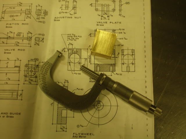
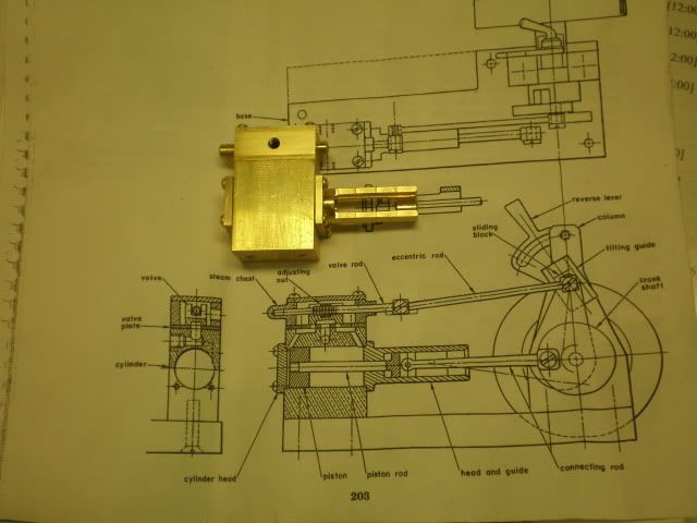
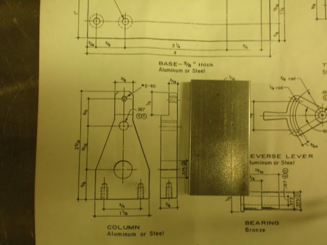
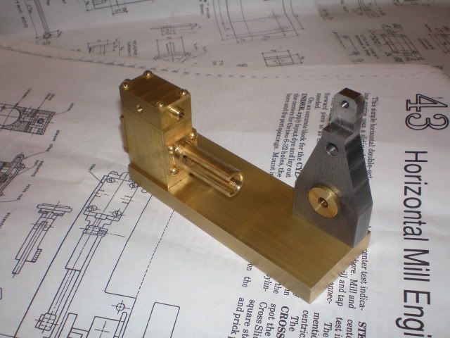
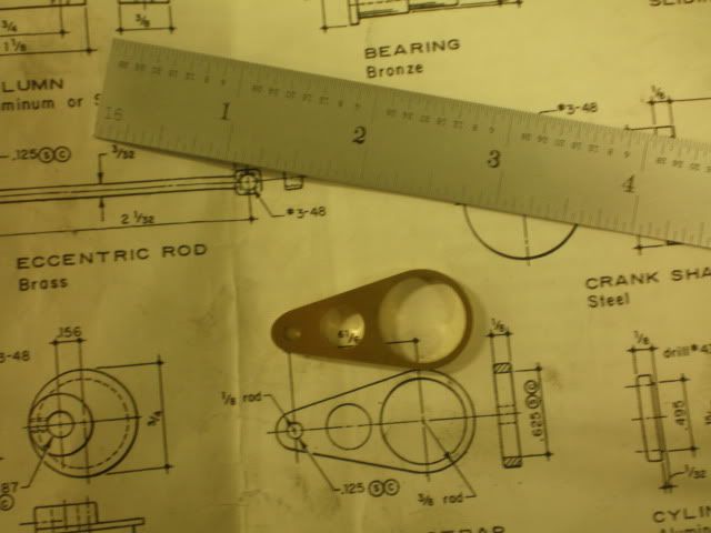
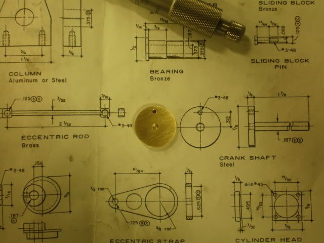
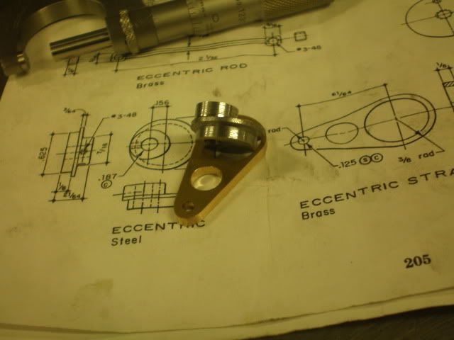
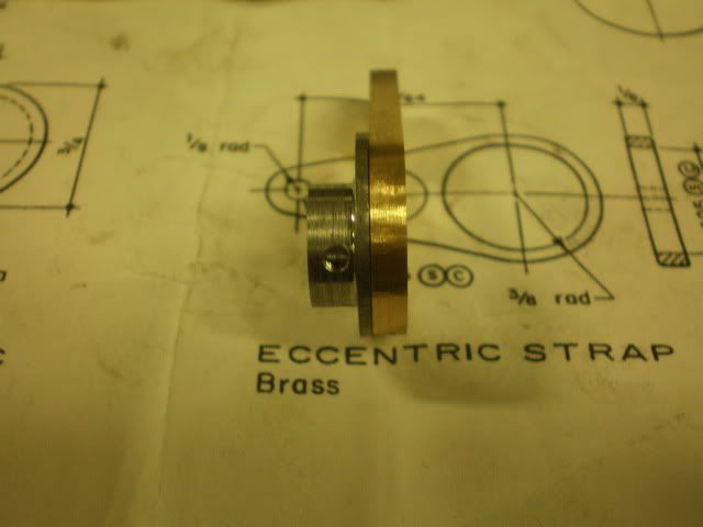
Thought I'd make a engine that allowed a minimum amount of operator interaction and after following Zee's saga Elmer's 43 seemed a natural. Plus it let's me try out my newly purchased el-Cheapo Enco 5c collets and collet block set. So far - so good...
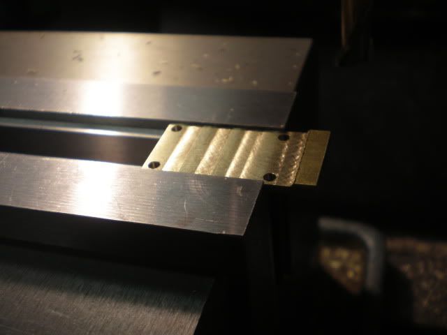
Crosshead build:
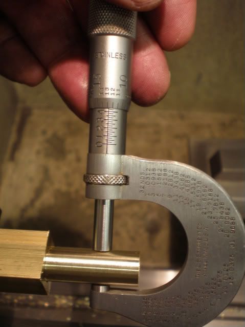
7/16ths? Close enough:
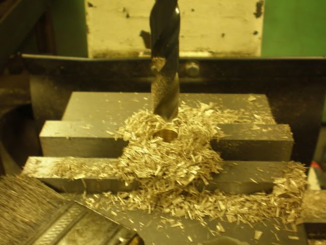
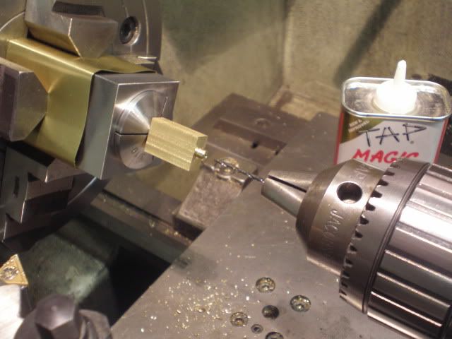
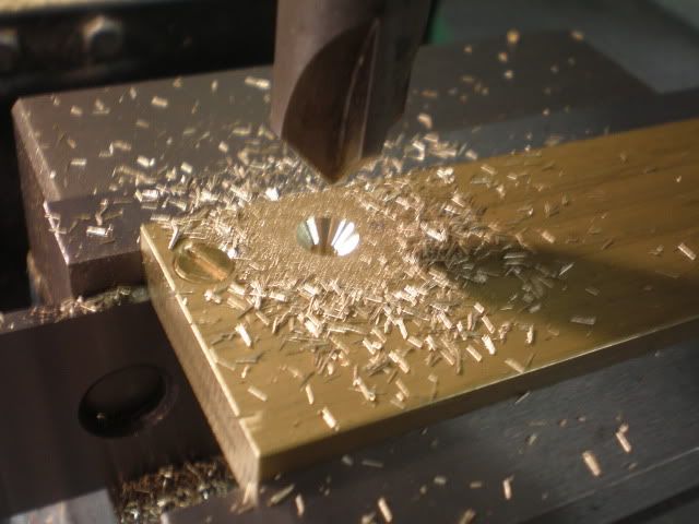
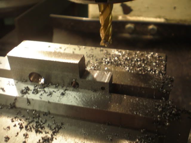
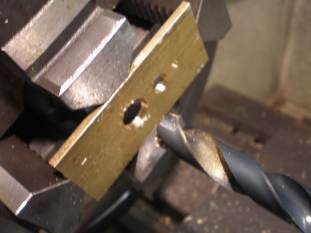
Drill and ream:
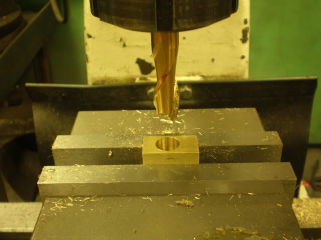
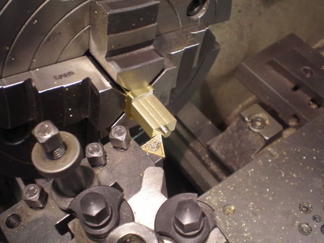
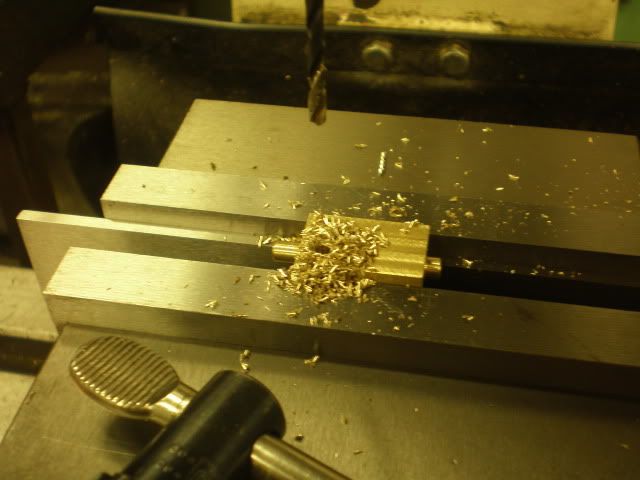
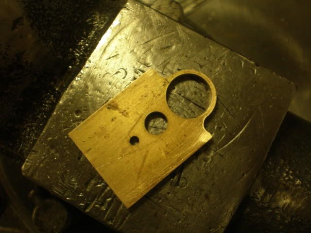
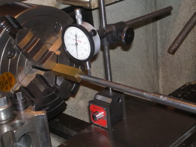
Remove, cut, mount in collet block and indicate:
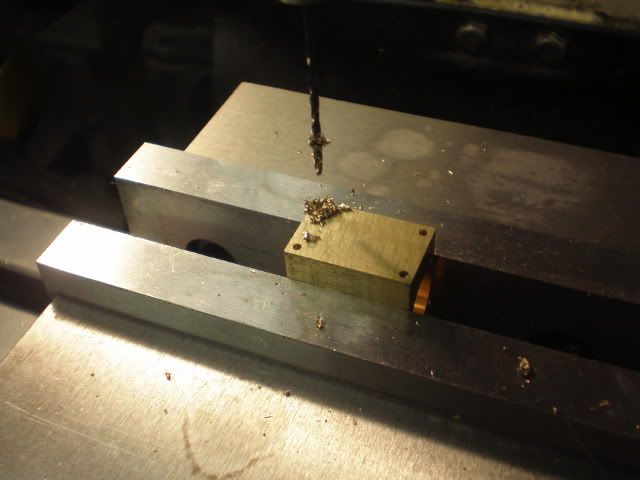
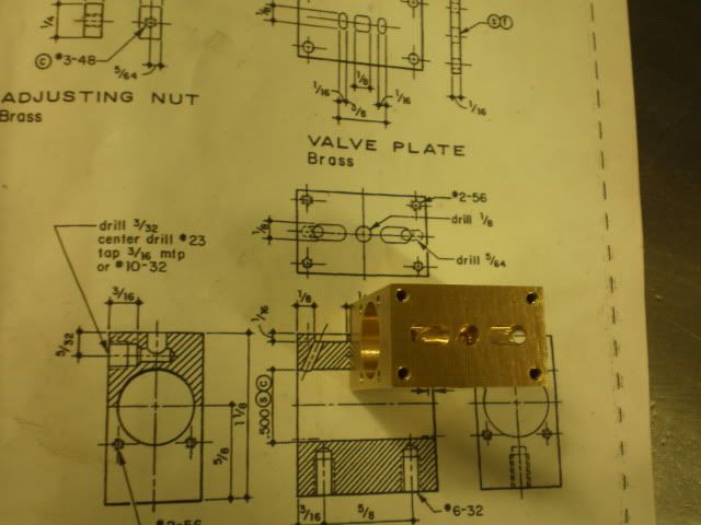
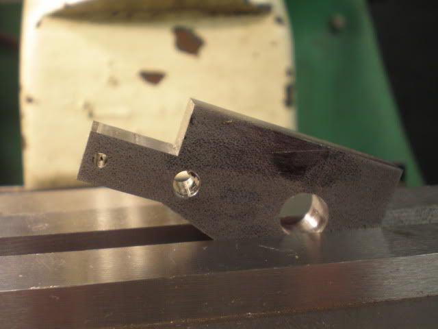
Finish cylinder head end:

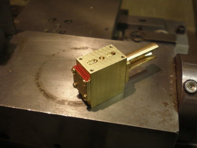
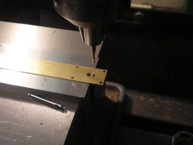
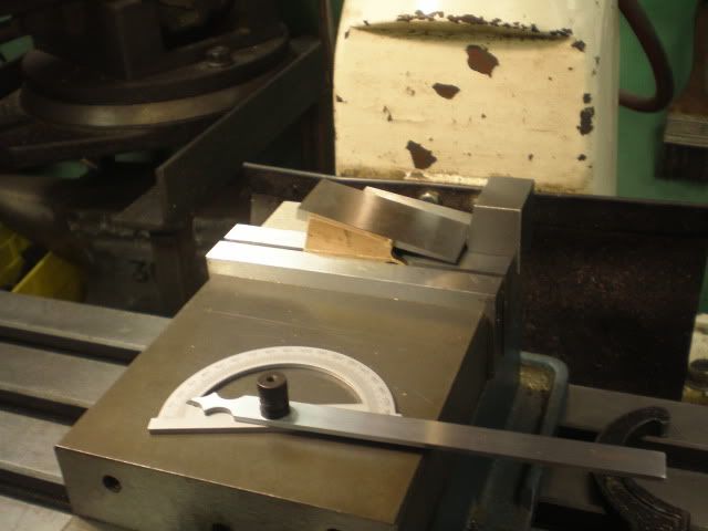
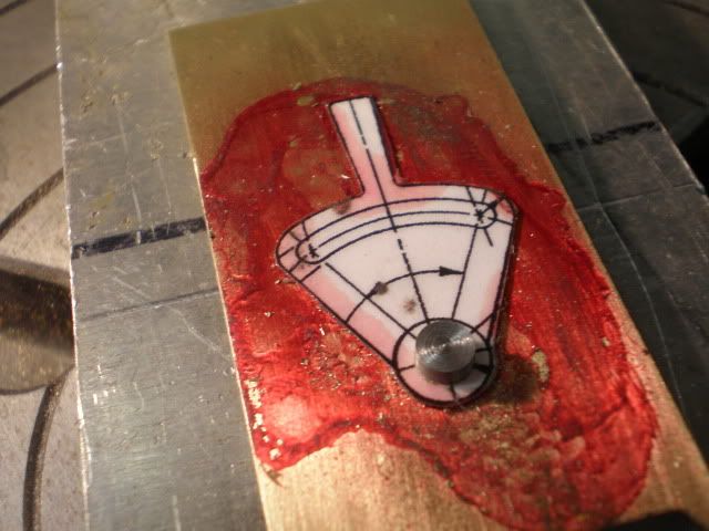
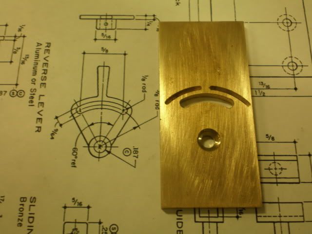
Some more drilling and milling:
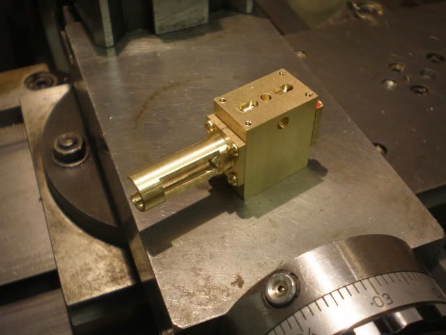
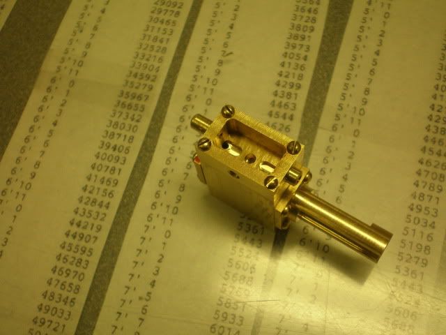
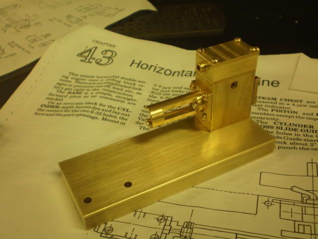
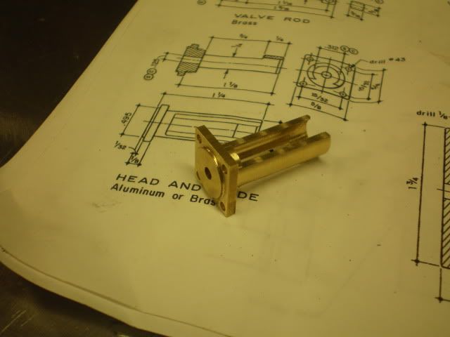
Good to go...
Will start on the cylinder next.
Jim
Crosshead build:
7/16ths? Close enough:
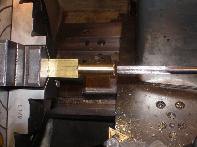
Drill and ream:
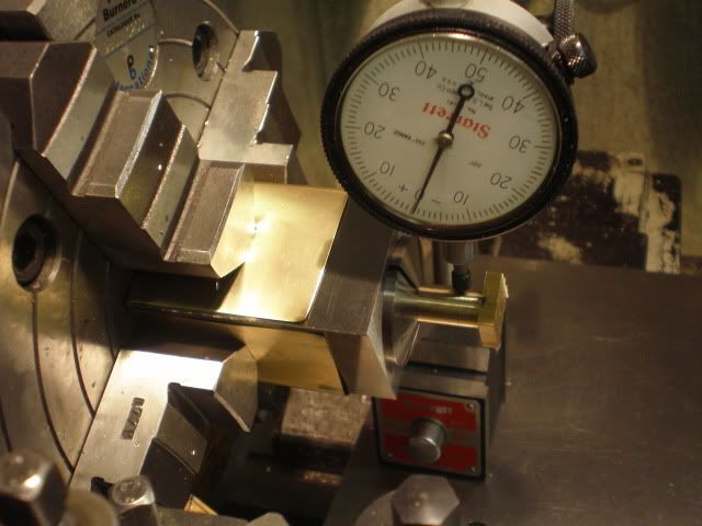
Remove, cut, mount in collet block and indicate:
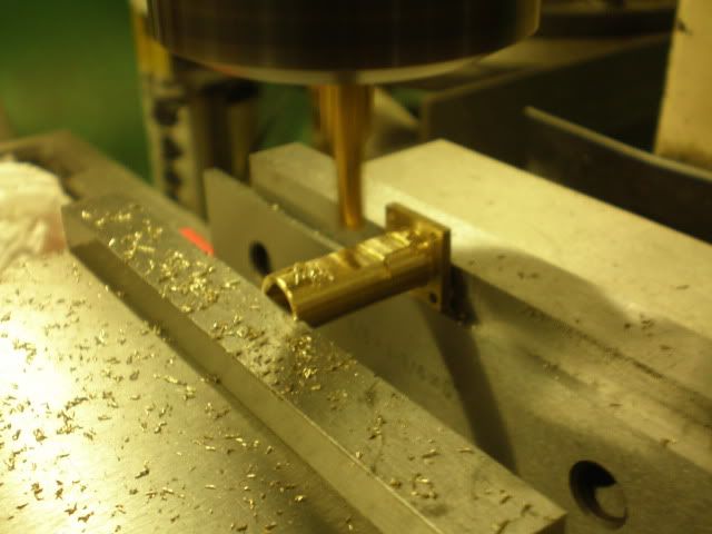
Finish cylinder head end:
Some more drilling and milling:
Good to go...
Will start on the cylinder next.
Jim