Sshire
Well-Known Member
- Joined
- Jun 29, 2011
- Messages
- 936
- Reaction score
- 259
Two Engines In One or Elmer Gets a Makeover
This is a cautionary tale about what happens when you decide to build an engine but don't like some of the design.
Elmer Verburg is probably looking down on this build and either thinking, "Hey, what's wrong with square blocks as cylinders?" or laughing uncontrollably. Or, perhaps, both.
Let me explain.
Elmer's Radial has square cylinders. Not actually a square cylinder, but a round hole bored in a square chunk of metal. Now a bunch of you are saying, "If it's good enough for Elmer..."
It bothered my sense of design. I wanted a round hole in a round chunk and if that isn't enough, I wanted some of those cooling fins in the round chunk. There probably isn't a time in the foreseeable future when this will run on anything but air so the cooling fins are nothing more than another skill to add on to the very short list of skills I've acquired in the last 11 months since I've started this hobby. (My 5th grade teacher would have cringed at that fine example of a run on sentence.)
Not willing to learn enough CAD to create a model, I jumped right in. In the process of "design-as-you go", I've created enough parts for, at least two engines. Hence the title of this build.
Since the only thing I've changed from Mr. Verburg's plans are the cylinders, let's begin there. This isn't where I actually started, so you may notice that some parts, like the crankcase, pistons, rods, etc. seem to have magically materialized. Believe me, they did not and I will get to the build steps for those in due course.
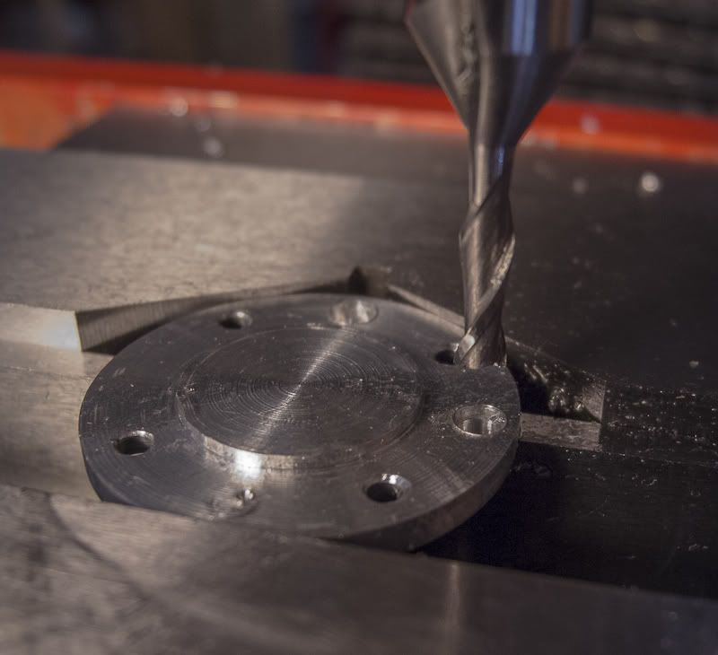
The simplest approach seemed to drill and bore the cylinder, as Elmer intended, in a square chunk of 6061. Then put it in the 4-jaw and make it round. So I did. Bad idea. The air passage was too close to the outer diameter of the cylinder to cut the cooling fins.
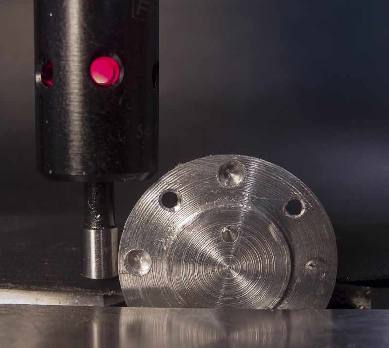
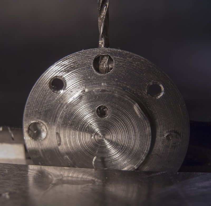
Aha! I'll offset the bore to leave more metal where the air passage is drilled.
Bad idea #2. Now there's not enough metal for the four through mounting holes. Plus ( or minus) the depth of the cooling fins is too wimpy.
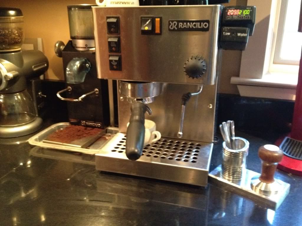
Only one thing to do. Go upstairs and make a double-shot of espresso.
After thinking about this, I came up with two possible solutions (well, three actually but I disregarded, "quit and make more espresso.")
Plan #1. Increase the diameter of the cylinder (duh)
Plan #2. Forget the through holes for mounting and air passage and do them externally.
So I did both.
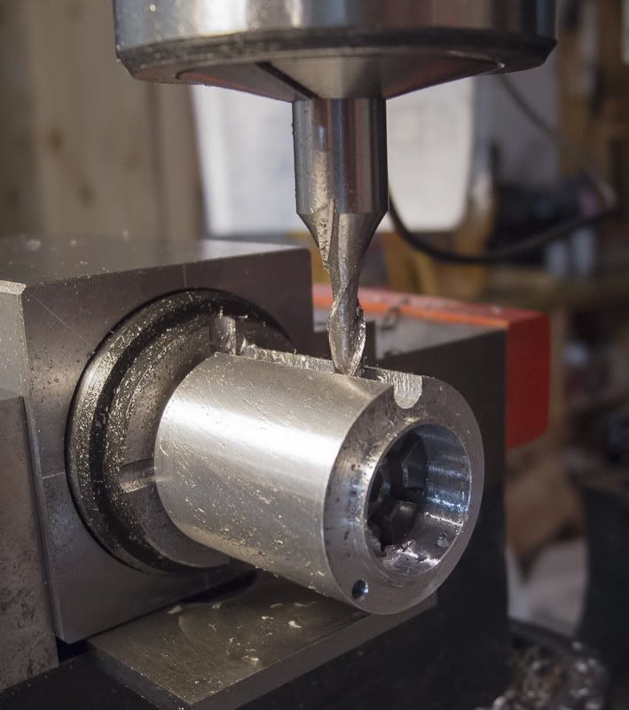
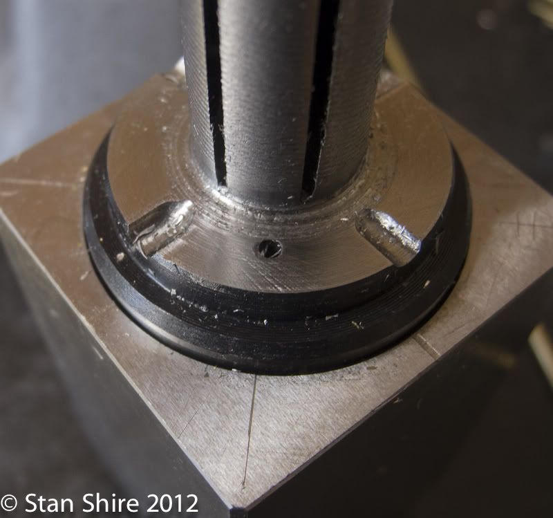
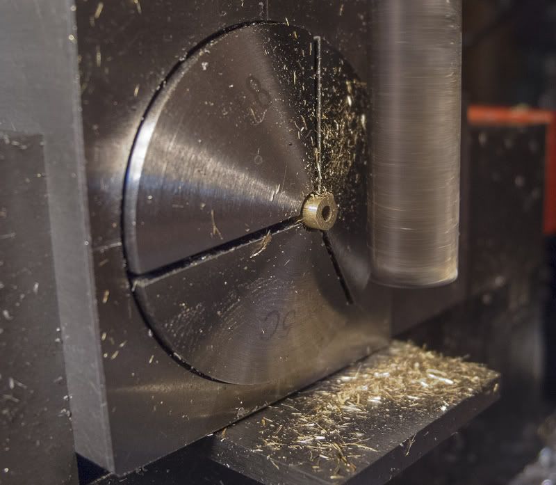
After turning a larger 6061 piece to 1.1" and boring the cylinder, I mounted it on a 5C expansion collet and milled grooves with a .125 ball end mill for the external hold down pieces.
The air passage hole near the bottom will also be a milled groove.
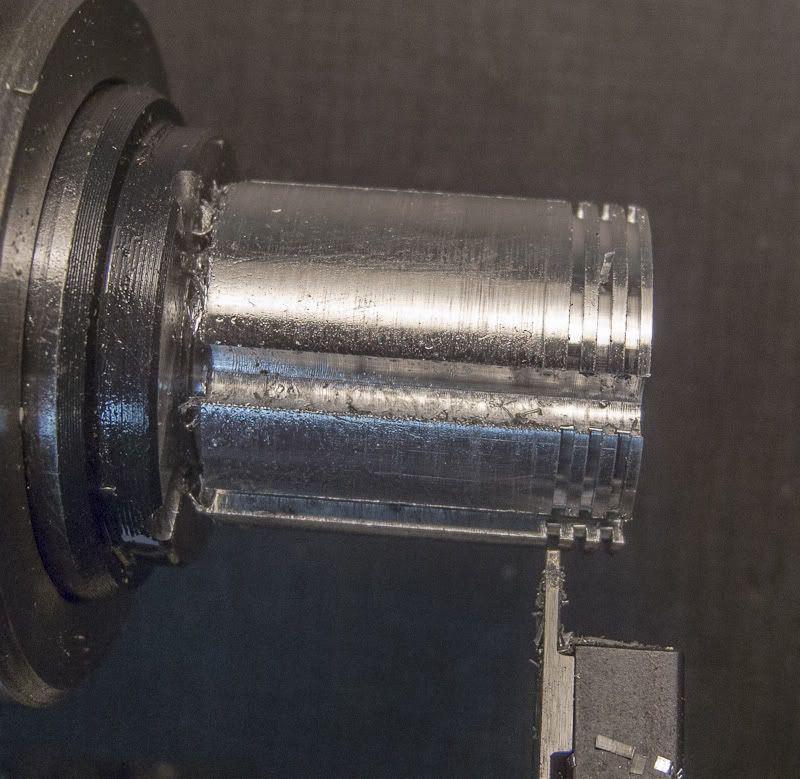
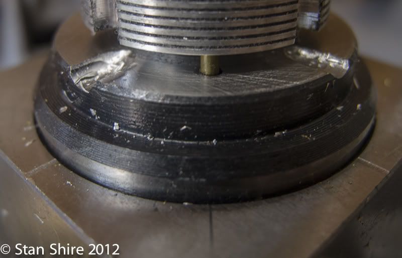
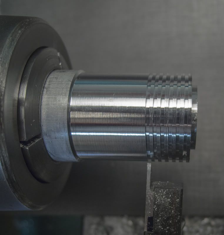
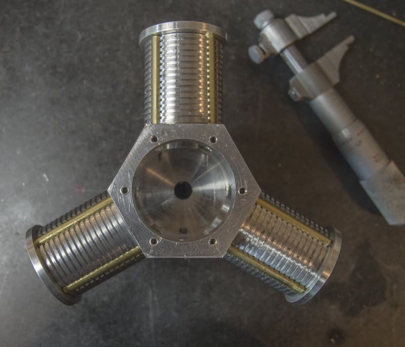
The cylinder, still on the collet, went over to the lathe and I cut grooves with a Warner grooving tool. I spaced the grooves equally with a dial indicator measuring the lengthwise travel and the depth with the DRO.
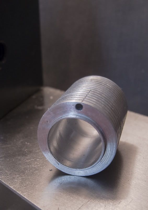
Three finished cylinders and they got to this stage in only 5 days of making "extra" cylinder variations.
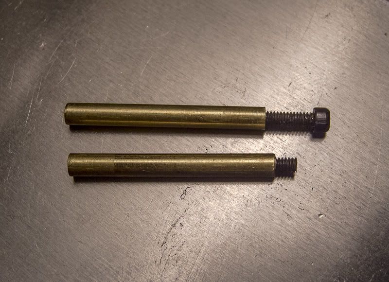
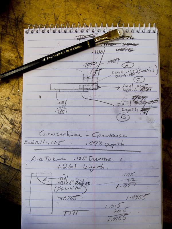
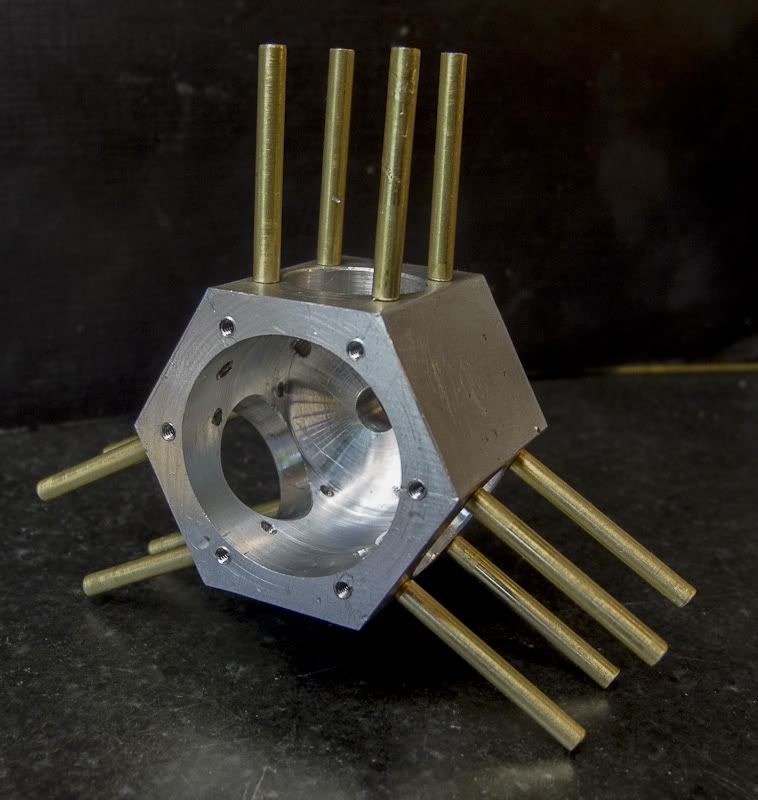
My thought for the hold down pieces was to use .125 brass tubing. Cut to length, drill and tap 2-56. I would Loctite short pieces of 2-56 SHCS in one end and screws through the cylinder head at the other.
Now I needed to set of steps to make all of the tubing exactly (or as close to "exactly" as I can make them.)
So
1. Cut 12 pieces close to the finished length
2. Use a collet stop set for the length I needed. The 5C collet will be in a collet block.
3. Vise stop on the mill so I can return the collet block to the same position.
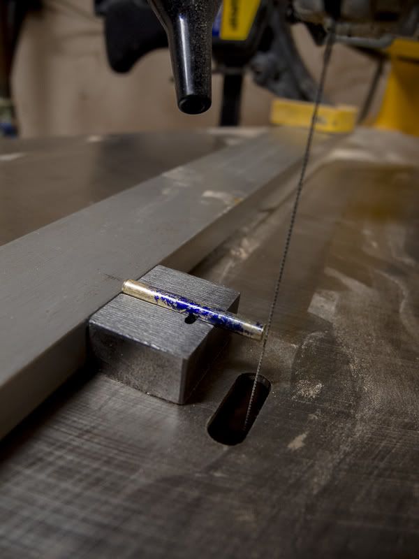
Clamped a straightedge to the jigsaw table. Fine tooth metal cutting blade in place. Cut all 12 pieces of .125 tubing about .1 over finished size. Deburred the ends.
I put one of the pieces into a ⅛" 5C collet, set a collet stop inside, put the whole thing into a square collet block. The block then went in the mill vise and I milled the end to split a line I had marked on the setup piece of tubing. I measured the piece in the 1"-2" micrometer and found that I was .009 over. Easy enough the use the DRO on the mill to move X over by .009. Now I locked everything down and did the remaining 11 pieces.
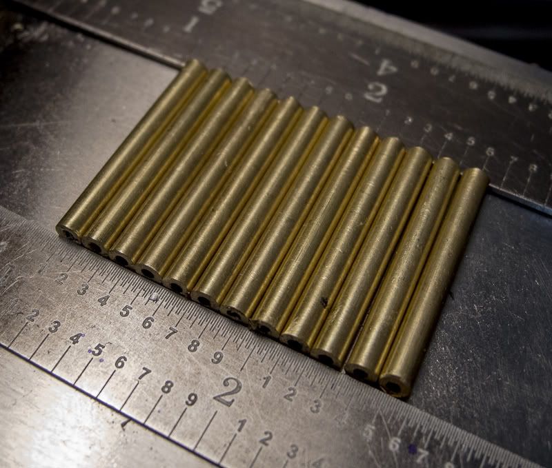
Done and all the same size.
And now, a short digression.
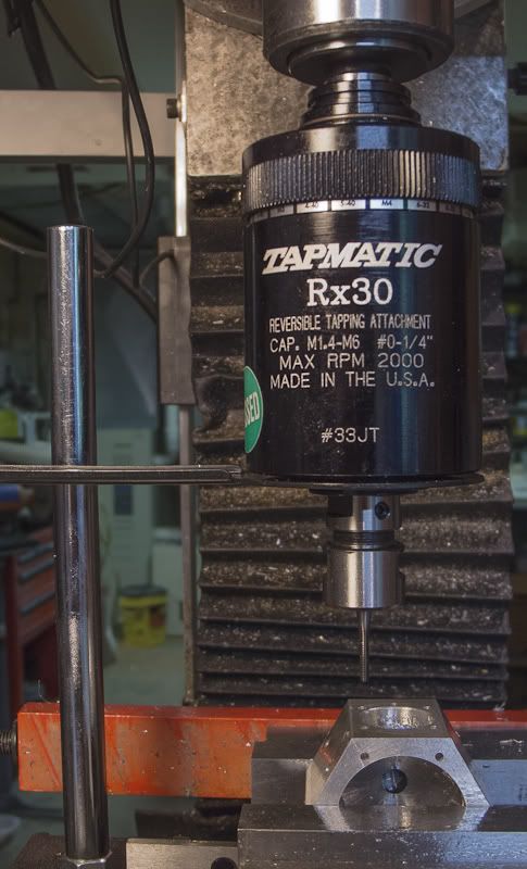
The crankcase has 24, 2-56 threaded holes to be tapped. Never passing up an opportunity to bolster the economy, a Tapmatic RX30 mysteriously appeared in the shop. After some research and a very nice discussion with an engineer at Balax (they make wonderful form taps), and some discussion here on the forum about tapping oils ( some of which, apparently, are quite "fragrant"), thread percentage and other mysterious topics, I did a few test holes to set the torque. A butt-clenching period followed while I tapped all 24, 2-56 holes in about 3 minutes with nary a broken tap. I was prepared to break a few in testing, so I had ordered 4. I still have 4.
End of short digression.
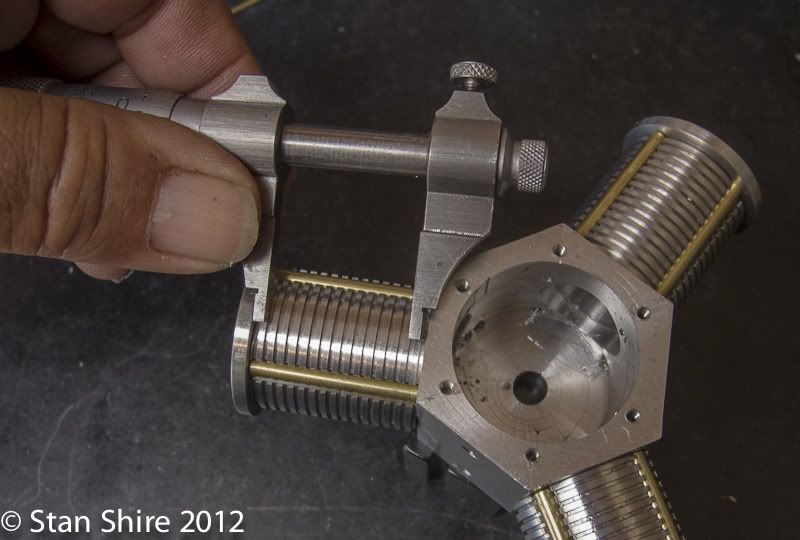
So here's where we are.
Stay tuned for the next part where I try to figure out how to get air into the cylinder and make more espresso.
Best
Stan
This is a cautionary tale about what happens when you decide to build an engine but don't like some of the design.
Elmer Verburg is probably looking down on this build and either thinking, "Hey, what's wrong with square blocks as cylinders?" or laughing uncontrollably. Or, perhaps, both.
Let me explain.
Elmer's Radial has square cylinders. Not actually a square cylinder, but a round hole bored in a square chunk of metal. Now a bunch of you are saying, "If it's good enough for Elmer..."
It bothered my sense of design. I wanted a round hole in a round chunk and if that isn't enough, I wanted some of those cooling fins in the round chunk. There probably isn't a time in the foreseeable future when this will run on anything but air so the cooling fins are nothing more than another skill to add on to the very short list of skills I've acquired in the last 11 months since I've started this hobby. (My 5th grade teacher would have cringed at that fine example of a run on sentence.)
Not willing to learn enough CAD to create a model, I jumped right in. In the process of "design-as-you go", I've created enough parts for, at least two engines. Hence the title of this build.
Since the only thing I've changed from Mr. Verburg's plans are the cylinders, let's begin there. This isn't where I actually started, so you may notice that some parts, like the crankcase, pistons, rods, etc. seem to have magically materialized. Believe me, they did not and I will get to the build steps for those in due course.
The simplest approach seemed to drill and bore the cylinder, as Elmer intended, in a square chunk of 6061. Then put it in the 4-jaw and make it round. So I did. Bad idea. The air passage was too close to the outer diameter of the cylinder to cut the cooling fins.
Aha! I'll offset the bore to leave more metal where the air passage is drilled.
Bad idea #2. Now there's not enough metal for the four through mounting holes. Plus ( or minus) the depth of the cooling fins is too wimpy.
Only one thing to do. Go upstairs and make a double-shot of espresso.
After thinking about this, I came up with two possible solutions (well, three actually but I disregarded, "quit and make more espresso.")
Plan #1. Increase the diameter of the cylinder (duh)
Plan #2. Forget the through holes for mounting and air passage and do them externally.
So I did both.
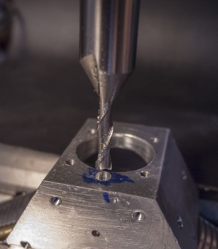
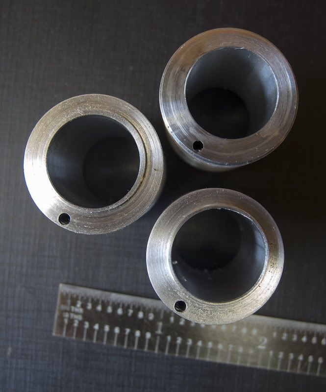
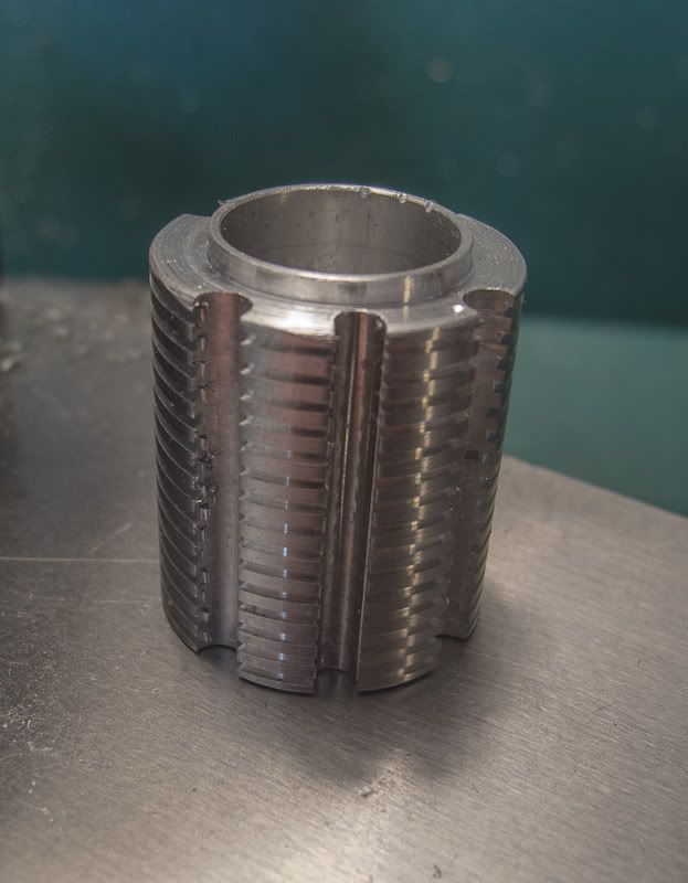
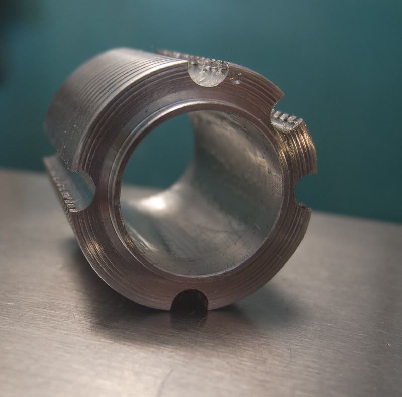
After turning a larger 6061 piece to 1.1" and boring the cylinder, I mounted it on a 5C expansion collet and milled grooves with a .125 ball end mill for the external hold down pieces.
The air passage hole near the bottom will also be a milled groove.
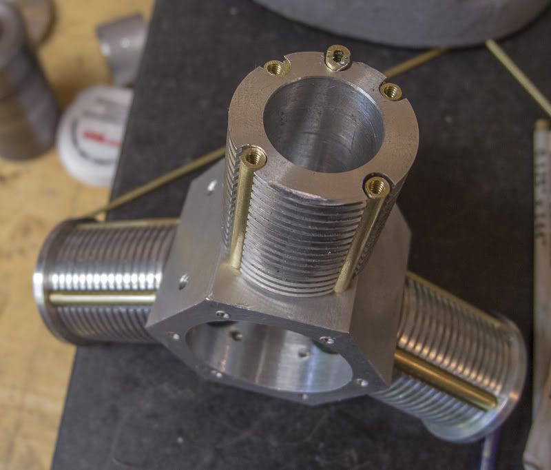
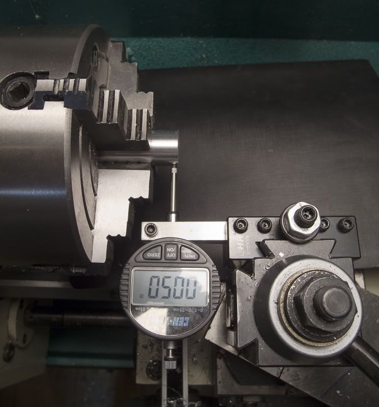
The cylinder, still on the collet, went over to the lathe and I cut grooves with a Warner grooving tool. I spaced the grooves equally with a dial indicator measuring the lengthwise travel and the depth with the DRO.
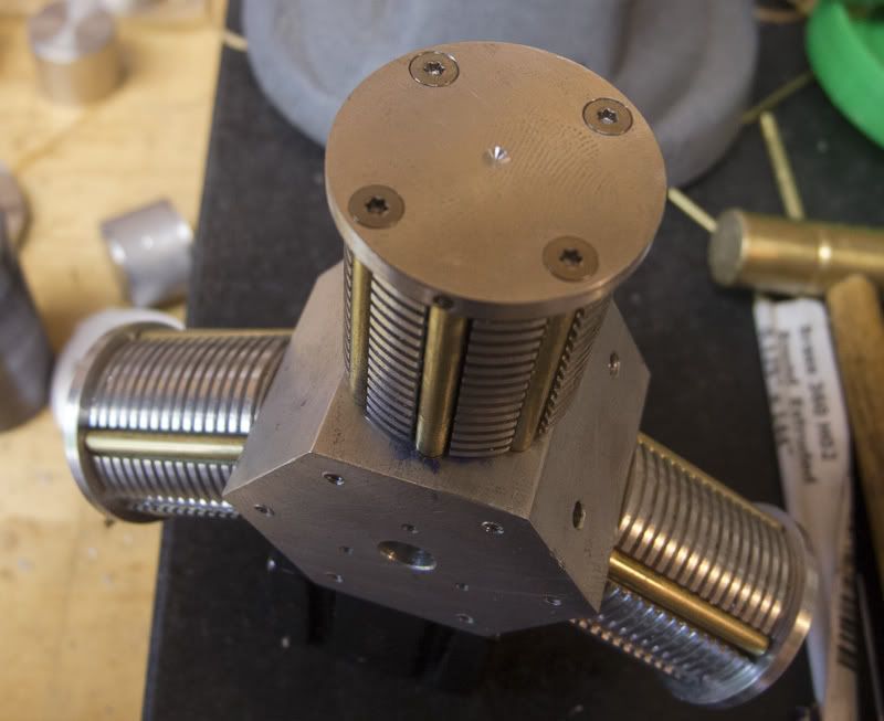
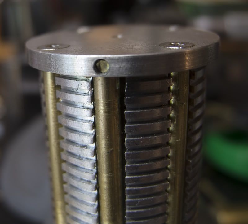
Three finished cylinders and they got to this stage in only 5 days of making "extra" cylinder variations.
My thought for the hold down pieces was to use .125 brass tubing. Cut to length, drill and tap 2-56. I would Loctite short pieces of 2-56 SHCS in one end and screws through the cylinder head at the other.
Now I needed to set of steps to make all of the tubing exactly (or as close to "exactly" as I can make them.)
So
1. Cut 12 pieces close to the finished length
2. Use a collet stop set for the length I needed. The 5C collet will be in a collet block.
3. Vise stop on the mill so I can return the collet block to the same position.
Clamped a straightedge to the jigsaw table. Fine tooth metal cutting blade in place. Cut all 12 pieces of .125 tubing about .1 over finished size. Deburred the ends.
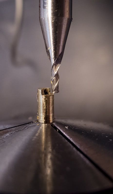
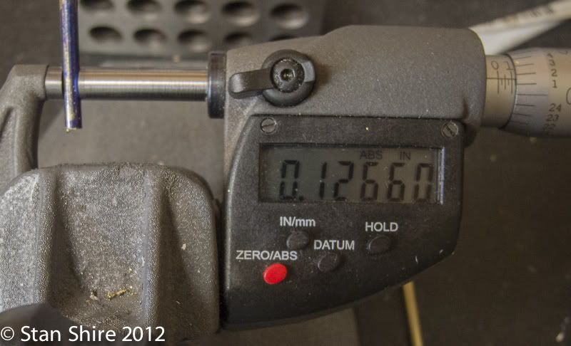
I put one of the pieces into a ⅛" 5C collet, set a collet stop inside, put the whole thing into a square collet block. The block then went in the mill vise and I milled the end to split a line I had marked on the setup piece of tubing. I measured the piece in the 1"-2" micrometer and found that I was .009 over. Easy enough the use the DRO on the mill to move X over by .009. Now I locked everything down and did the remaining 11 pieces.
Done and all the same size.
And now, a short digression.
The crankcase has 24, 2-56 threaded holes to be tapped. Never passing up an opportunity to bolster the economy, a Tapmatic RX30 mysteriously appeared in the shop. After some research and a very nice discussion with an engineer at Balax (they make wonderful form taps), and some discussion here on the forum about tapping oils ( some of which, apparently, are quite "fragrant"), thread percentage and other mysterious topics, I did a few test holes to set the torque. A butt-clenching period followed while I tapped all 24, 2-56 holes in about 3 minutes with nary a broken tap. I was prepared to break a few in testing, so I had ordered 4. I still have 4.
End of short digression.
So here's where we are.
Stay tuned for the next part where I try to figure out how to get air into the cylinder and make more espresso.
Best
Stan
")