Elmers #33 - Mill Engine
Episode 11
Elmer! Come in for dinner!
Elmer Verburg sits at his drafting table putting the finishing touches on a steam chest drawing.
Lets see. Intake ports. Threaded mounting holes. Nine tiny holes. Ha! That should give the guys with .050 backlash a fun day.
Hmm, did I miss anything? Oh, yes. The hole for the exhaust port. I have it on the cutaway but not on the top face drawing. Also need a drill size for the hole.
Elmer picks up his pencil to add the missing elements to the drawing.
Suddenly, Elmer! Come in for dinner. You can finish that later.
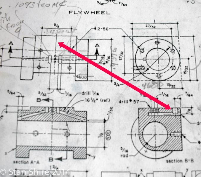
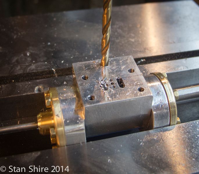
Of course, Elmer never does add the two missing elements and I spent some time this morning figuring that one out. When I made the cylinder, I remember noting that the exhaust had to exit somewhere, but in the frenzy of making the other parts, like Elmer, I forgot. So the cylinder goes back on the mill for drilling the exhaust channels.
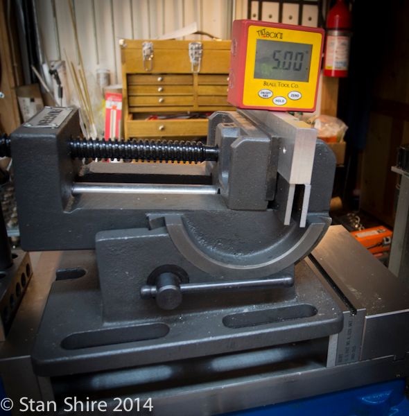
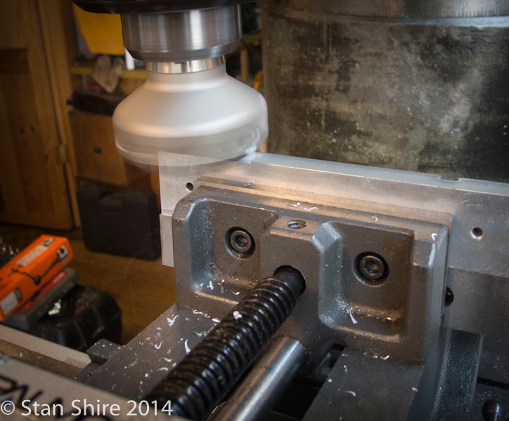
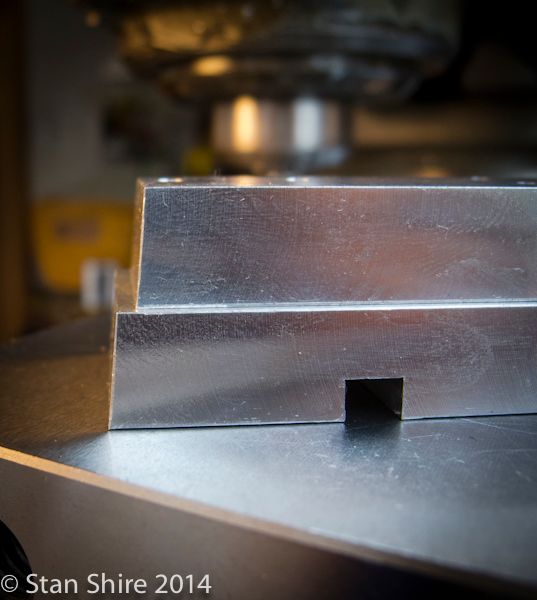
Now to bevel the base and sub-base. The angle isnt critical; its supposed to suggest that the bases were cast and have a draft angle. 5 degrees looked about right so the angle vise was clamped in the Kurt (anything not to have to re-indicate the Kurt).
The 2 face mill bevels the long sides
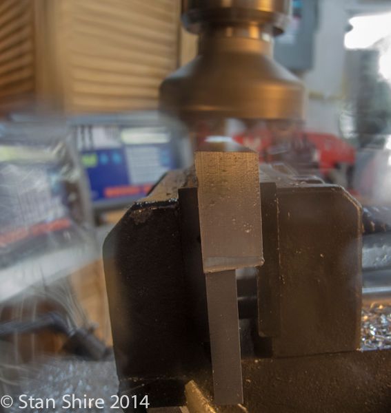
A side view.
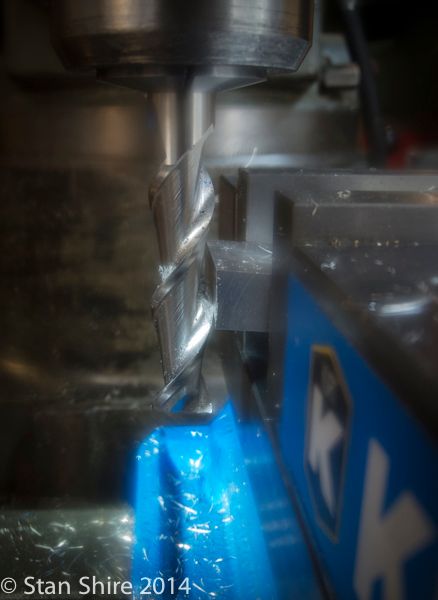
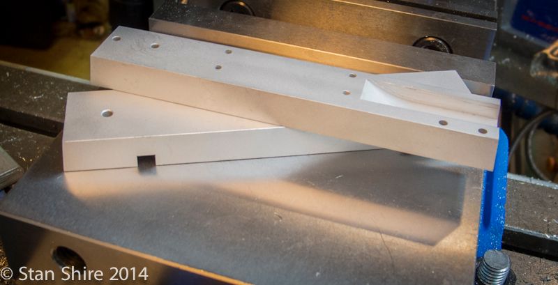
Now that those edges are finished, the ends will be done. I used a high helix end mill. Nice finish on the non-ferrous stuff.
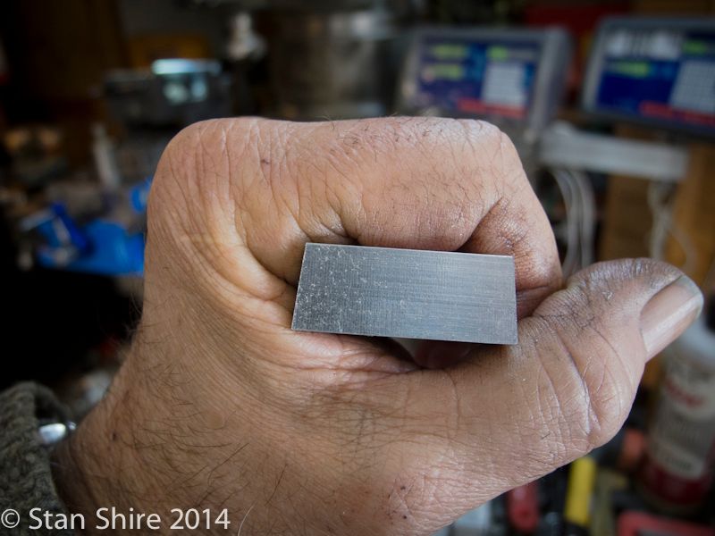
Milling is finished.
The machining marks removal department.
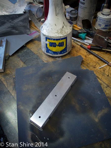
Since the base and sub-base are going to be painted, I started by bead blasting the parts.
This was followed by self-etching primer and black gloss enamel.
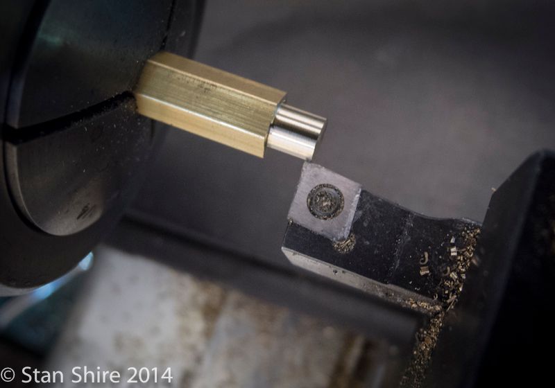
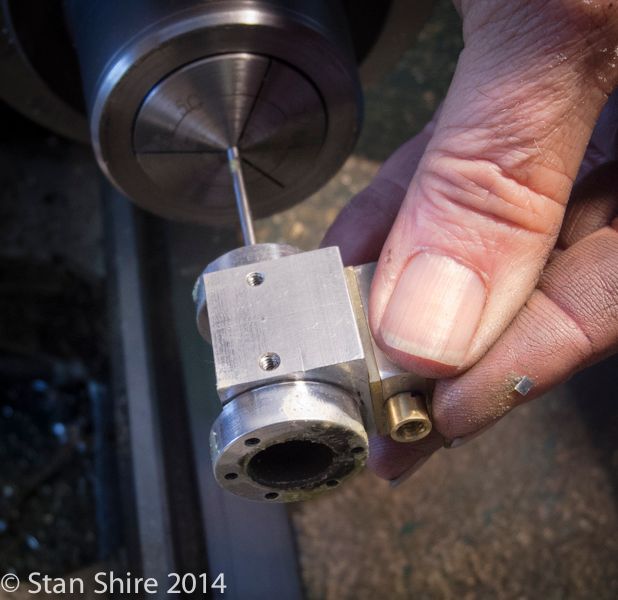
While the paint is drying, I moved on to the two pack nuts: one for the steam chest valve rod and the other for the piston rod. Started with .250 brass hex in a 5C collet. Marked the part to be threaded to length.
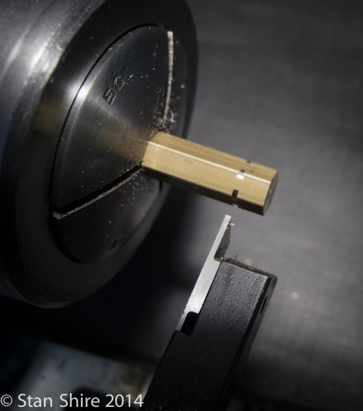
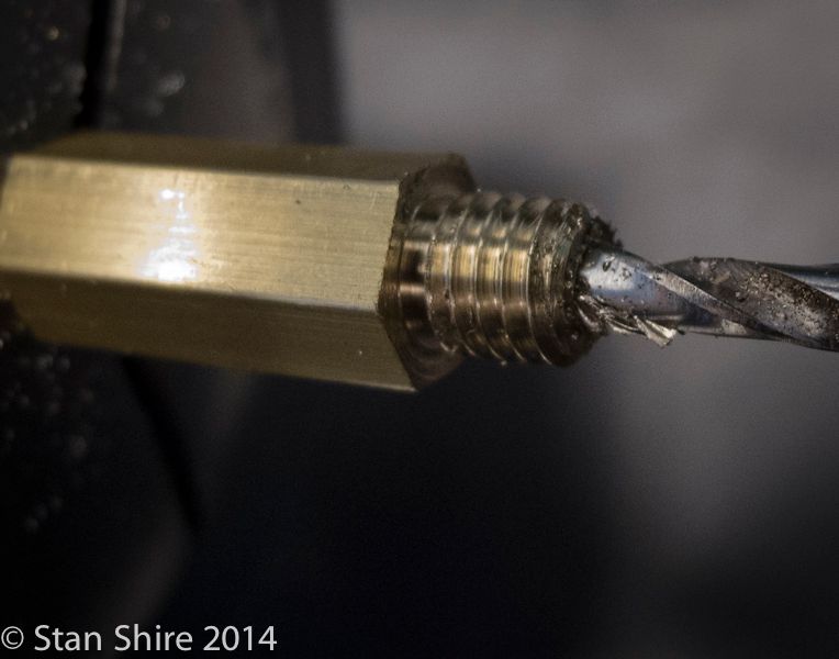
Then turned to something under .190 (.186 IIRC) for the 10-32 thread.
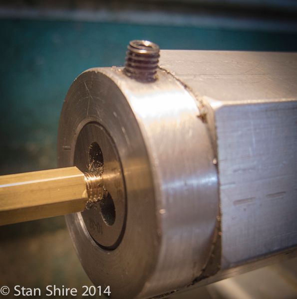
Through drilled for the rods then, parted off.
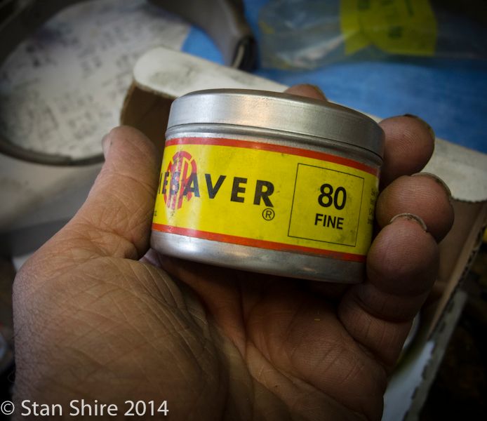
The piston was just the littlest bit tight. Timesaver fixed that.
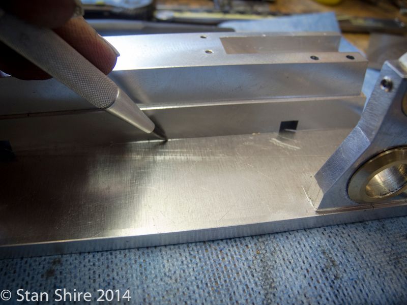
Ive decided to do the floor in lumber planking. First I scribed around the bearing tower and the sub-base. This will tell me where NOT to lay my flooring.
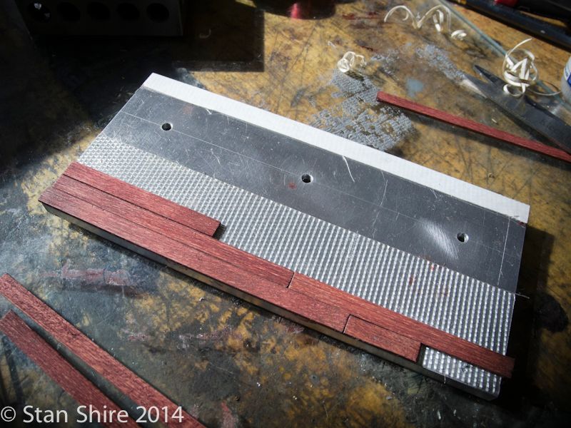
Basswood stripping with Bartleys Gel Stain. Cutting and fitting followed.
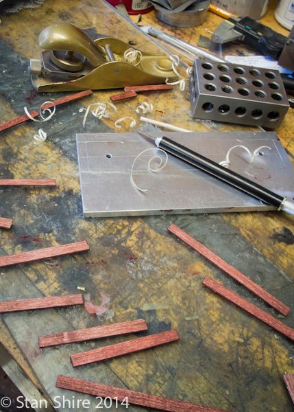
Double-stick carpet tape to affix the stripping.
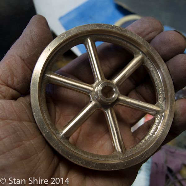
Youll see that when its finished. If you dont know by now, Richie is my UPS guy. Since he brought the flywheel casting from PMR, that needed to be addressed.
The soft jaws went onto the 3-jaw chuck. They were tensioned at about the right diameter and bored to grip the bronze flywheel casting.
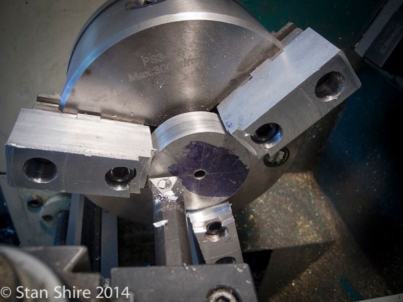
More than half of the rim can be reached for truing.
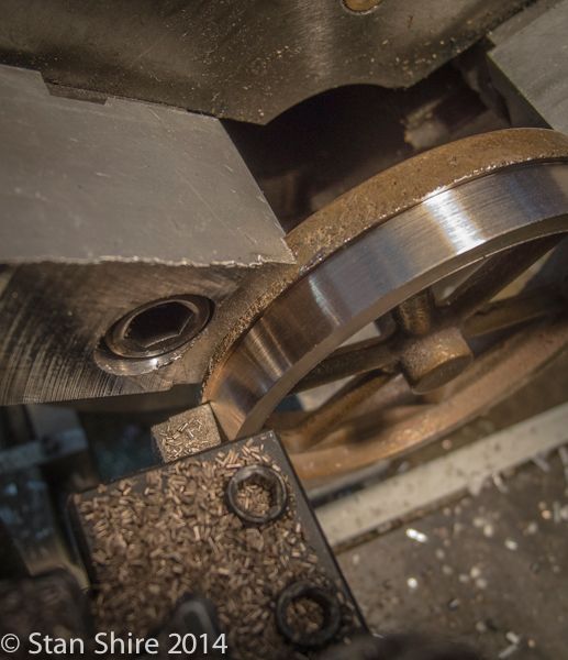
Then, faced and the hub faced and turned. The part is then reversed in the soft jaws. Repeat.
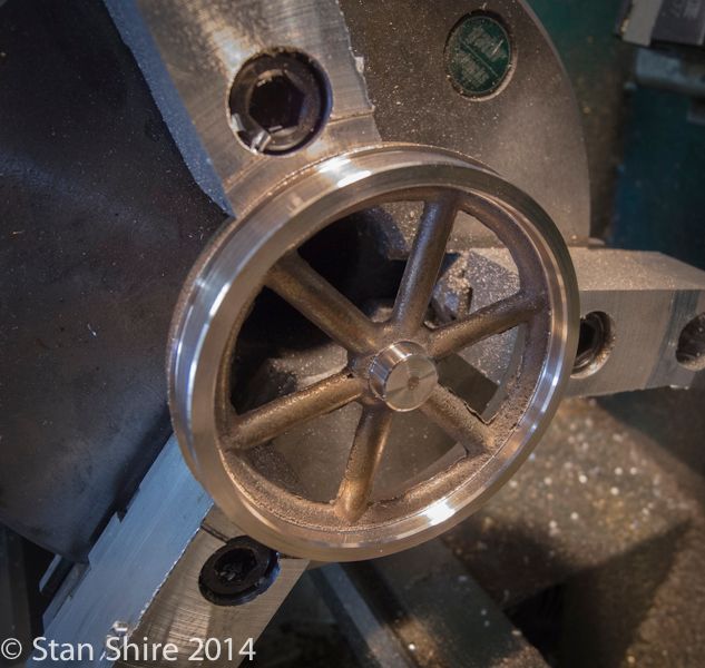
Then drilled a bit under-size and reamed to .250
Oliver removed the flash and cleaned up the corners.
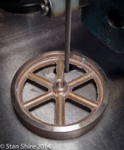
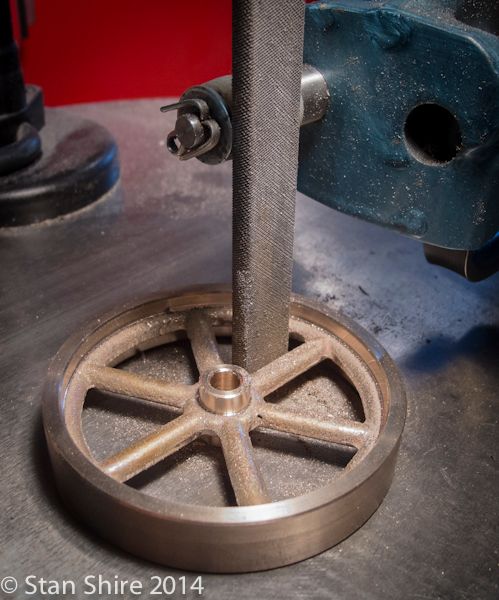
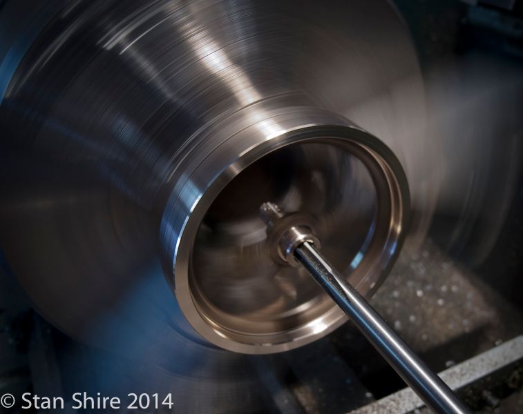
Then to the bench. I started with 80 grit then 100, 120 and 220. I use the fabric-backed abrasive rolls and use a piece until it stops cutting or looks like old denim.
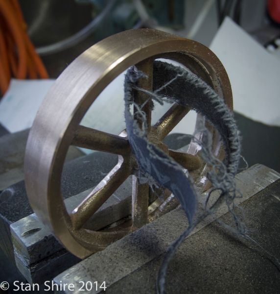
This is where I stopped for the day. Still need to smooth between spoke at the rim, then masking, priming and painting. Thats for tomorrow.