Elmer's #33 - Yet Another Mill Engine

Home Model Engine Machinist Forum

Help Support Home Model Engine Machinist Forum:

This site may earn a commission from merchant affiliate links, including eBay, Amazon, and others.
Heff

I see two issues with the grinder.

1. The spacing on this cylinder between the round ends is, IIRC, .825.

If the width of the wheel is less than this then that wiill work.

2. The bigger issue is aluminum loading the wheel. Pretty sure it would clog up quickly.


The rough rounding on the mill didn't leave all that much work to finish. Files would work pretty quickly and are easily unclogged, especially if they are chalked first.


You can get surface grinder wheels in just about any width you would like I go from 1/8"-1".
There are special wheels for grinding aluminum that they say will not load I've got those as well just need to try them out.

Todd


Sent from my iPad using Model Engines
 
Elmer’s #33 - Mill Engine
Episode 6
Bearing Down


It’s a conspiracy. Every time I started to do something on the engine, yet another interruption.
First, the tailstock lock on the lathe wouldn’t lock. So that came off, cleaned, adjusted the lockdown bolt, reset it. That was an hour.
Then, we had a few inches of snow last evening and I wanted to cleanup. Right. The snowblower refused to start. Had the holy trinity: gas, spark and air but no go.
I pulled the carb, disassembled and cleaned it. Reassembled with new float bowl gasket. Started right up. Another hour.
And that’s just about how the day went but I did get a little bit done.

The bearing housings have a sloped side and some other milling. First step was to mill flats at each side.


Note the very visible round insert. More on that later.


Then, with the angle fixture set at 20 degrees, a slope was milled on each side.


I decided to bling up the bearing housing with this insert.


I also decided that I liked being able to see the round top construction so I slightly recessed the insert rather than making it disappear as I did on the smaller one from the last post.


And is the total progress for today. Maybe fewer interruptions tomorrow.
 
Nice detail work Stan, keep it coming

Phil
 
When using surface grinders to grind copper and aluminium, we loaded up the wheel with candle wax to stop pickup. Just hold a candle against the wheel long enough to get the wax embedded, and off you go. You have to take it easy, no heavy cuts, but it works,

Paul.
 
Progress Report

I made the mill engine floor this morning.
Got the snowblower prepped for the projected 12+" of snow.
Filled all of the 5 gallon gas tanks in case the power goes out.
Sitting in front of the fire with a glass of fine Scottish produce and a very nice Vermont cheddar.
That is all.
 
Paul
It really is. Looking out of the window at the snow from last week covering the trees and the grass. Looks like one of those Budweiser Christmas commercials.
 
Stan, great build! One of my favorite Elmers.
I feel your pain about the snow. 107+" this season
just across from you here in Erie Pa in the northwest corner
on Lake Erie.

-2 deg. & brrrrrrr.....

Best wishes,
John
 
John
Don't you love lake effect snow? :D
 
My uncle lived in Eire for a while. Never got used to that special Great Lakes weather. In Muskegon we are somewhere over 100 inches. The snow banks are too high for the plows to push the snow over. Some roads are getting narrow. We could use one of those winter thaws.


Sent from my iPad using Model Engines
 
Elmer’s #33 - Mill Engine
Episode 7
Heads Up

Before we get started, and to get the UK Thread Police off my back about my use of brass all-thread…


KVOM kindly sent me 6 nuts to try. They are absolutely beautiful. I ordered 25 each of #2,4,6,8 and 10 from American Model Engineering Supply in Florida. Talk about a Mom and Pop shop. Pop makes the fasteners and Mom runs the office. Spoke with Barbara (Mom) on the phone. Nice people.

So, today’s post-nor’easter activity was the cylinder heads.

Started with a piece of round brass to be turned to .91 something.


Drilled for the piston rod and then drilled a bit larger for the 10-32 threaded pack nut.


Threaded with a spiral point tap which pulls the chips out of the hole.


Then to the mill for the bolt hole circle.


Back to the lathe for parting off


Then I switched to a smaller collet to reverse the piece and hold the spigot. The locating boss is .03 deep.


Test fit. Looks fine.


I have 12 bolts to shorten. Hey, Let’s make a tool!!

A piece of 6061 milled in thickness to the bolt length I need. Drill some 2-56 holes for a form tap.


And tap 12 holes in under 2 minutes (not counting the 10 minutes to setup the tapping head)


Bolts inserted


And, cut off


Backing them out cleans up the threads


Yes. It did take longer to do that than to cut 12 bolts with a jeweler’s saw but, the next time I have to cut 2-56 bolts to .25” in length….

That finishes the inboard head.


The outboard head is just a cylinder cover. No spigot; no threading.

I faced the part, moved it to the mill, drilled the bolt hole circle and then came back to the lathe.
After parting the piece off I reversed it in the collet. Didn’t have more than .0625 to grip but I did have to indicate the face to turn the locating boss.


The outboard head done.


Probably the steam chest tomorrow.

Thanks for stopping by.
 
Like the bolt cutting technique. I look at stuff like that, and it's so simple, yet ingenious.


Sent from my iPad using Model Engines
 
Elmer’s #33 - Mill Engine
Episode 8
The Eccentric Machinist or A Boring Episode


The eccentric is pretty straightforward. Mounted the 4-jaw and indicated the brass round to center.


A bit of drilling and reaming on center.


Then, moving the center 0.50” to turn the eccentric.


Sharpened the HSS insert. Happy with the finish.


Parting off and done.


This seemed like a good time to line bore the bearings. I turned a piece of brass tube to maintain the spacing between the bearing housings and used the planer gauge as a bottom support. This whole operation would have been quicker with adjustable parallels as spacers. (if I had any) The shaft will be .25” O.D. Im using ball bearings with an O.D. of .375. Drilled and reamed to .375.


Now comes the part where I try something that:
A. I’ve never done before
B. I rarely see anyone else doing this way
C. Why the hell not?

The crank has a rounded bottom and curved sides. Rotary table! No, let’s try this another way.
I read somewhere about using a boring head with the cutter turned inward and the mill running in reverse to bore an O.D.

I laid out the crank on a piece of brass and rough cut close to the layout lines with the bandsaw.
The part was centered with the Blake’s center pop attachment.


When I say “rough cut” I really mean it. Drilled a 3/16” hole through the part and the plate for a dowel pin.


Then drilled and tapped through part and plate.


With the part held in place by the dowel pin and screw, I set up the boring head with the cutter facing in, the mill running in reverse at about 200 rpm.


Look good so far


O.D. boring done.


Now with the boring cutter facing out and the mill rotating normally, one side is cut.


Then the piece is flipped over to bore the other side.
I’ll be damned! That worked.


The small end was rounded at Oliver.


Now we need a spigot on the crank. Mounted a piece of 6061 in the 5C. Drilled and tapped for a 10-32 SHCS.


Some rough passes to get the thickness down.


And a finishing pass to complete the part.


So, now I’ve learned another way to make a crank. Never stop learning.
 
Very cool...it's always nice to see different approaches to doing things. It's funny how our brains work isn't it? That is what I really like about machining...there are so many ways to get the same results. And when you come up with a solution on your own...even better.

I just ordered a boring head kit...I'll have to store this technique away for another time.

Great job Stan.
 
Absolutely right, Chris. Figuring out how to hold, machine, assemble, etc. is one of my favorite things about this engine thing.
Am I going to see you and the other New England guys at Cabin Fever?
 
You will see plenty of New England guys for sure. I'm still up in the air if I want to make that drive again. If I do go, I won't be bringing any engines...just money to buy stuff I don't need!;)
 
Elmer’s #33 - Mill Engine
Episode 9
Fiddly Bits


The steam chest has many operations, many of them on tiny parts.
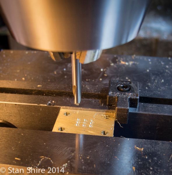
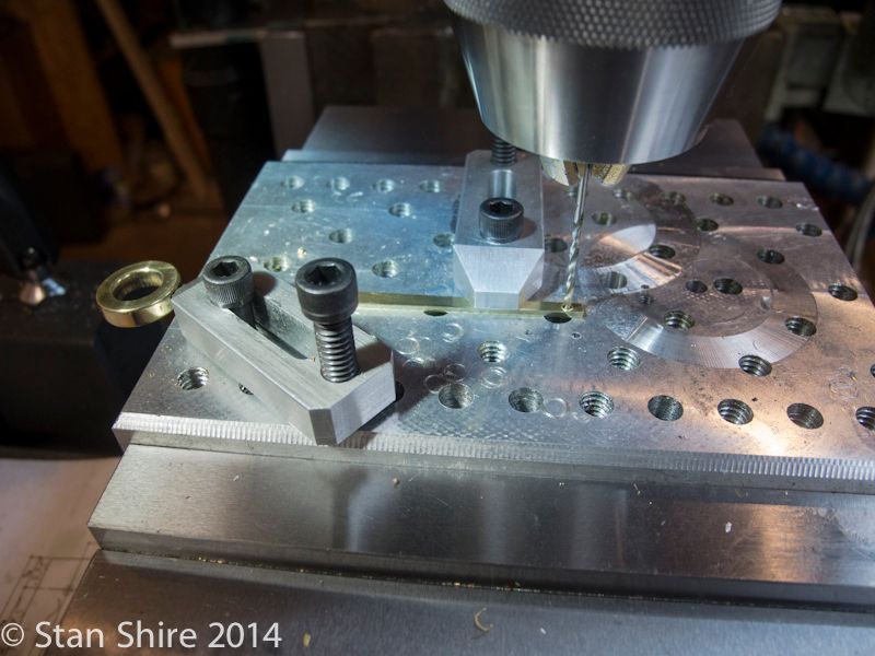
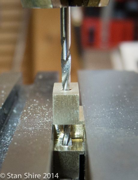
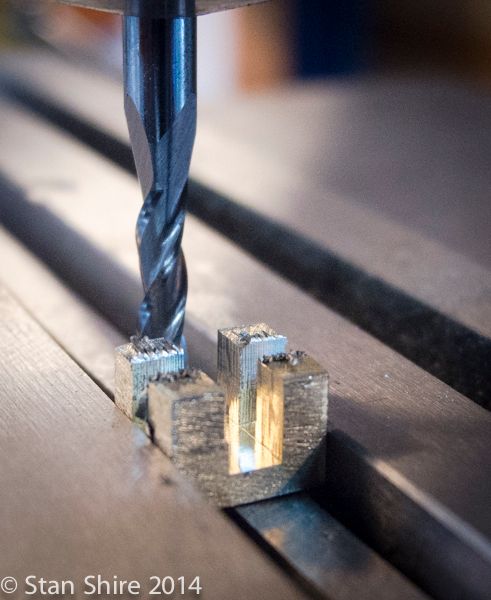
After squaring up the piece for the chest body, I located the centers and then cut through the corners.


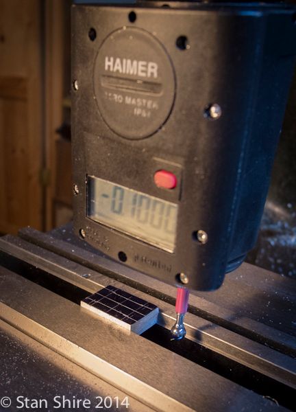
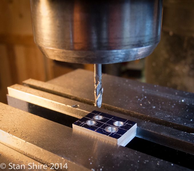
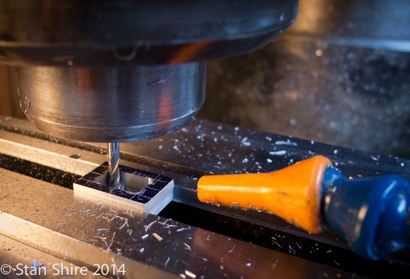
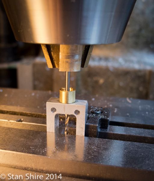
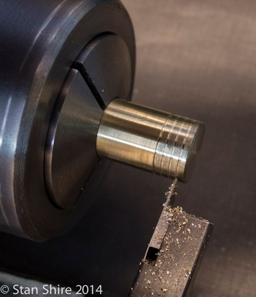
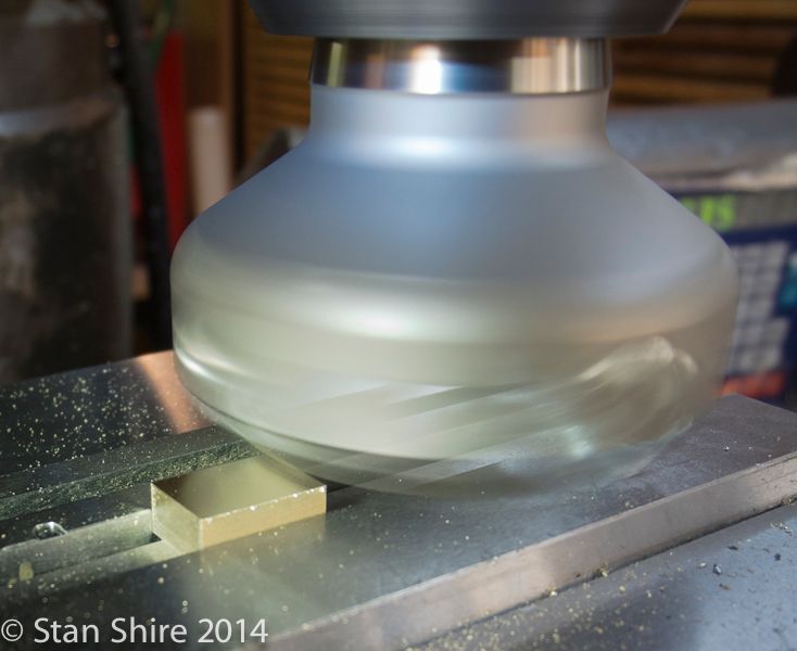
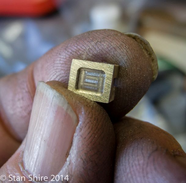
Then, very slowly, with one eye on the part and the other on the DRO, I transformed the inside into chips. The nozzle is blowing air to keep the chips clear. Keeps the end mill from getting jammed up with chips and breaking.
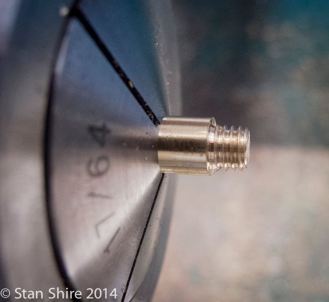
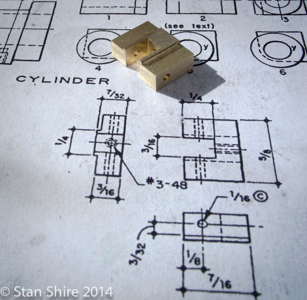


Elmer’s procedure is to mount the part in a 4-jaw and turn the end bosses (one for the valve rod and pack nut and the other for the rod guide. I did that on the Grasshopper but changed to threaded in bosses on later engines. I liked the contrast of the brass and aluminum.


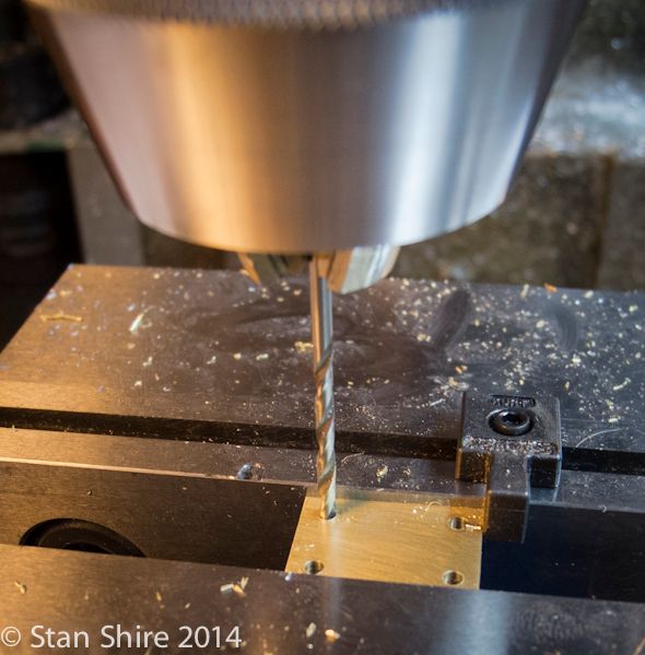
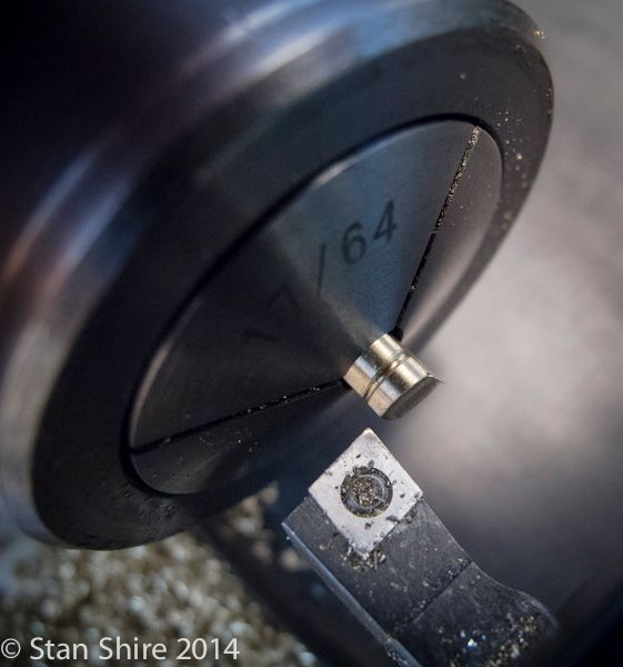
With both bosses threaded and Loctited into the steam chest, I line drilled through both, stopping just short of breaking through the guide boss.


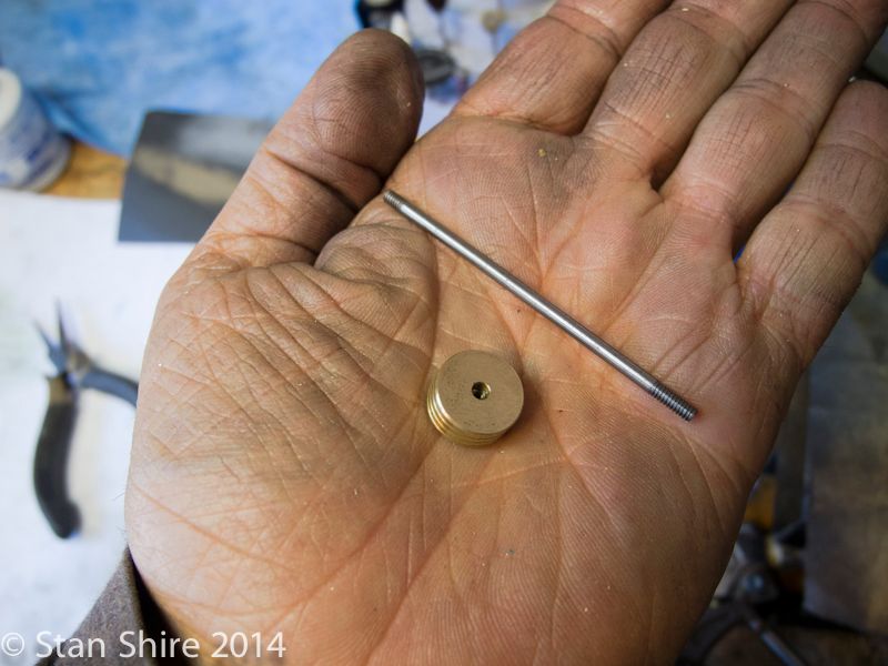
Next are the cover plate and valve plate. Also brass.


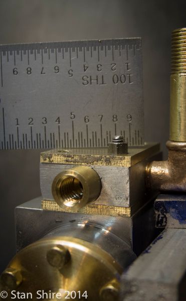
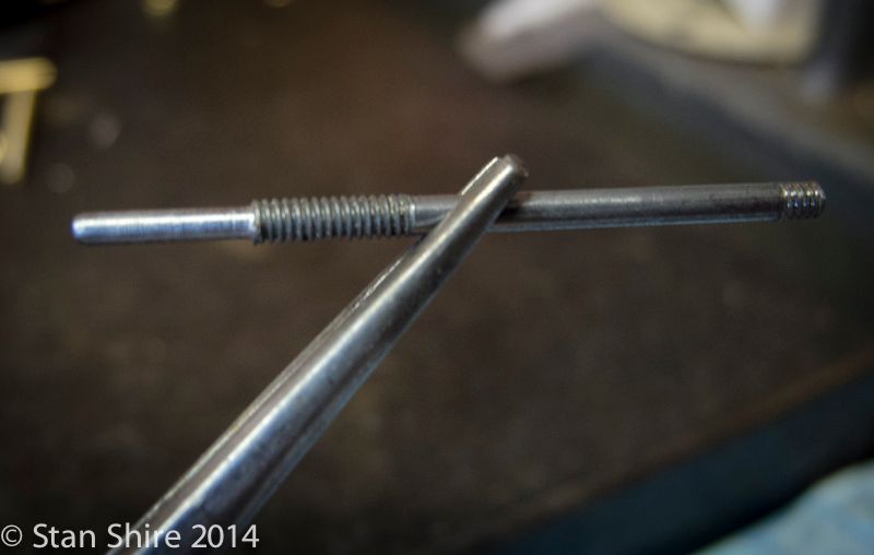
Test fit for alignment. LOOK!! 1.5 threads above the nut.


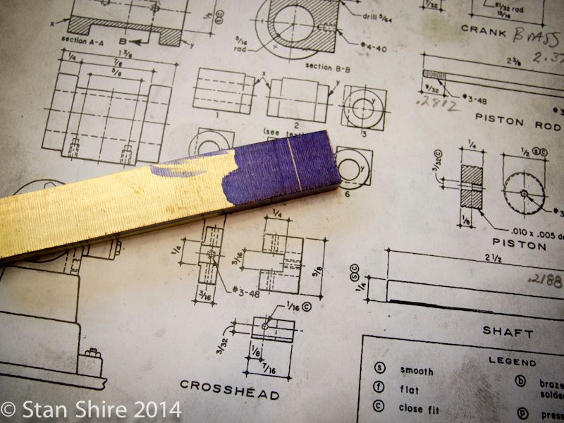
I setup this square bar for the connecting rod and decided to stop there and changed the part to a built-up con rod.


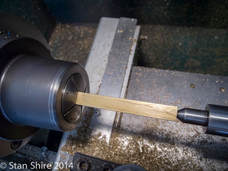
One end of the rod for a test fit.


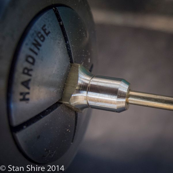
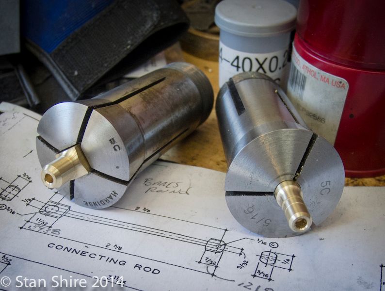
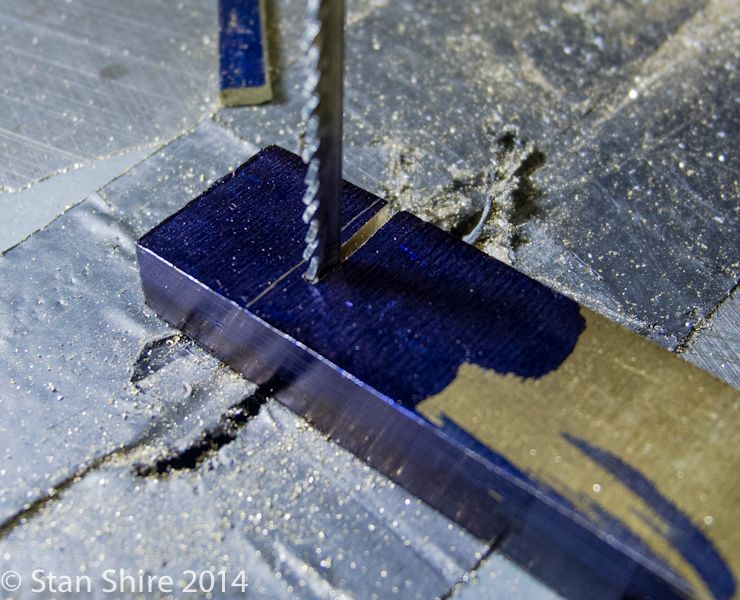
Both ends ready to go to the mill for flattening the sides and drilling the cross holes.


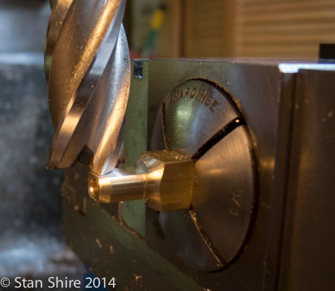
The part in a collet block. A flat was milled, the block was rotated 180 degrees and the opposite flat was milled. I didn’t drill the cross holes at this time because I wanted to wait until the ends were Loctited and cured. That way, the holes will be aligned. Elmer’s plans have the hole dimensions center-to-center.


Back at the lathe, The parts were reversed and cut to finished length.


Then bored for the rod.


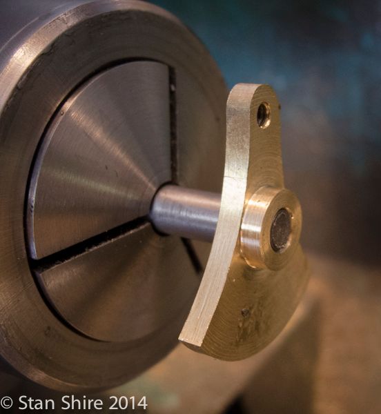
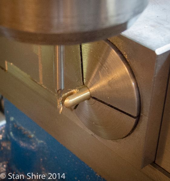
On to the Eccentric strap. Turned and bored at the lathe and then a .0625” slot was cut.


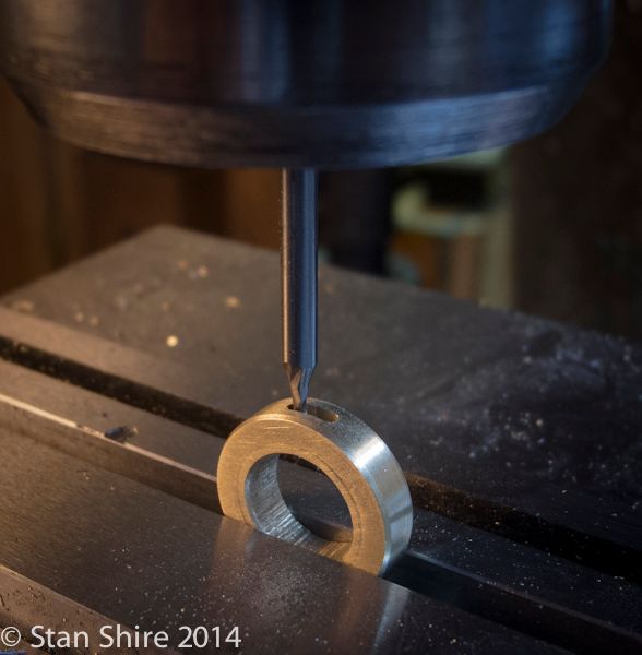
The strap was milled and both pieces were silver soldered.


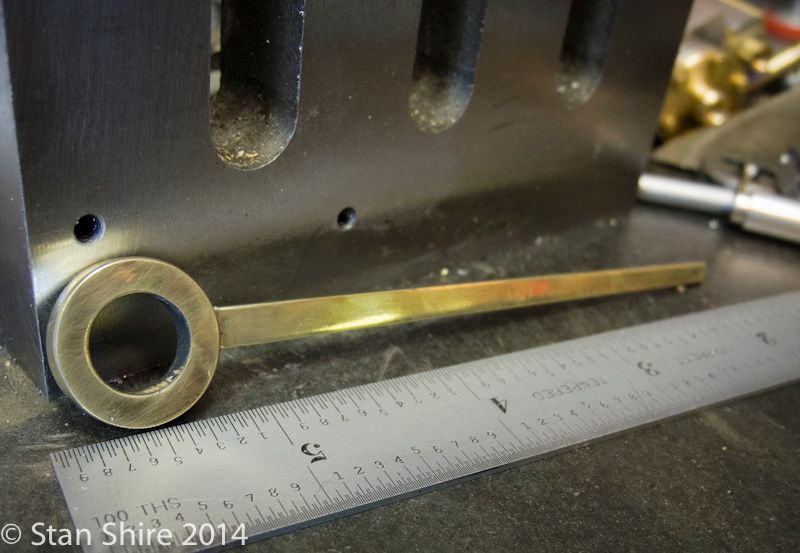
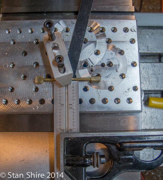
I located the center of the large hole, moved to Elmer’s dimension and drilled the other hole.


Then to the drilling on the connecting rod. I used the square to get the part parallel to the x-axis. I next ran a DTI along the rod to fine tune the parallelism. and drilled.


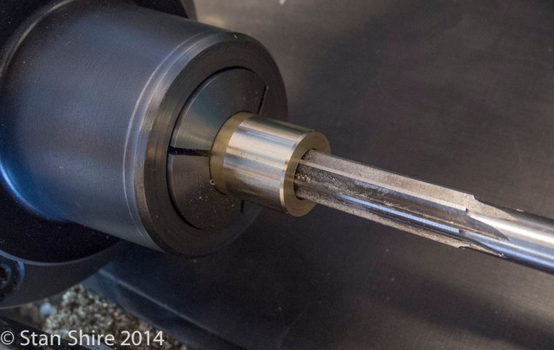
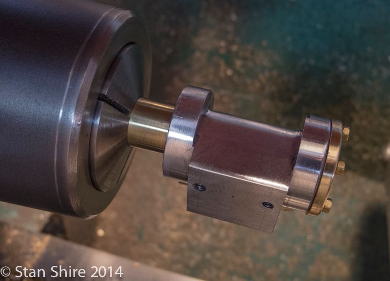
A test fit of the eccentric on the shaft.


And the final fit of the piston in the cylinder.


The piston has 3 oil grooves, .005 deep.


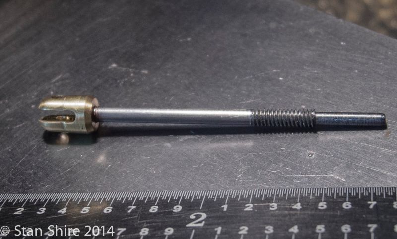
Then, drilling and tapping the piston and threading the piston rod. They were then Loctited together.


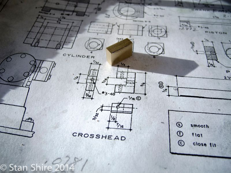
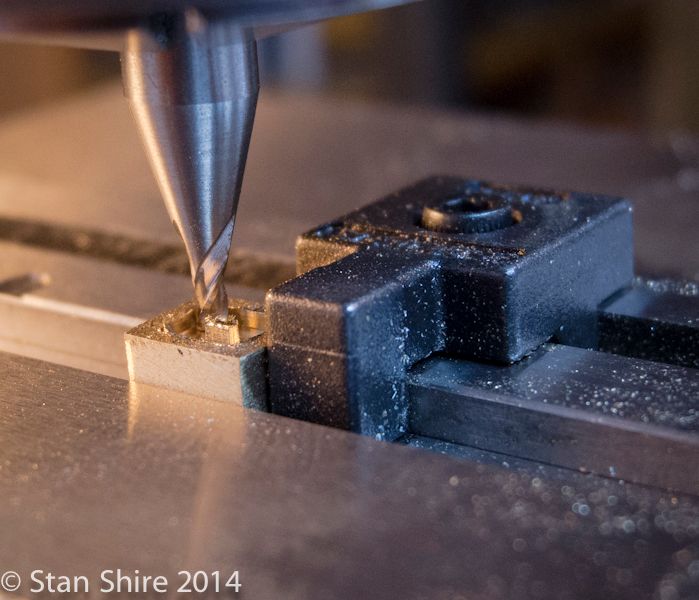
Now, on to the crosshead. I cut off a piece at the bandsaw and squared it up to size.


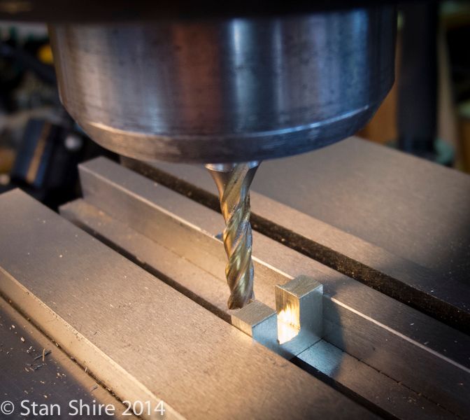
First, a guide boss was milled. This is the width of the crosshead guide spacing.
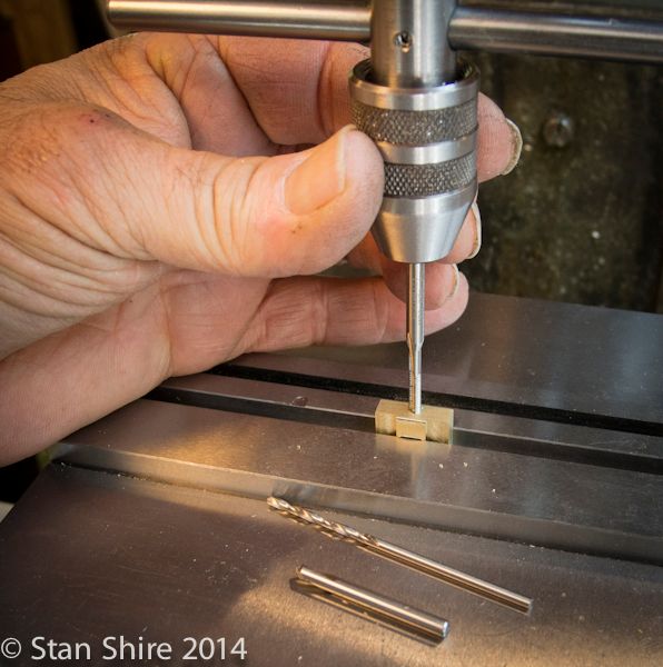
Then, one slot, one through hole and one cross hole.


The crosshead get checked off the parts list.


Talk about, “fiddly bits” and the valve has to be mentioned. Forget Finding Elmo. There is a valve in here somewhere.


.0625” stubby end mill. The vise stop looks huge compared to the valve.


More tiny milling


The valve bottom. Check that part off.


Next is the end that threads onto the valve rod. Some turning and shaping at the lathe, then a slot and cross hole at the mill.


The valve rod Loctited and curing.


Not too many parts to make. A shoulder bolt, some pins, the pack nuts and the flywheel.
Stay tuned.
 

Latest posts

Back
Top