Elmer's #33 - Yet Another Mill Engine

Home Model Engine Machinist Forum

Help Support Home Model Engine Machinist Forum:

This site may earn a commission from merchant affiliate links, including eBay, Amazon, and others.

Sshire

Well-Known Member
Joined
Jun 29, 2011
Messages
936
Reaction score
259
Elmer’s #33 - Mill Engine
Cross HeadCase
Episode 1


I’ve yet to make a mill engine and,since it’s been nearly 24 hours since I finished the cross twin, and I have that extra flywheel casting…


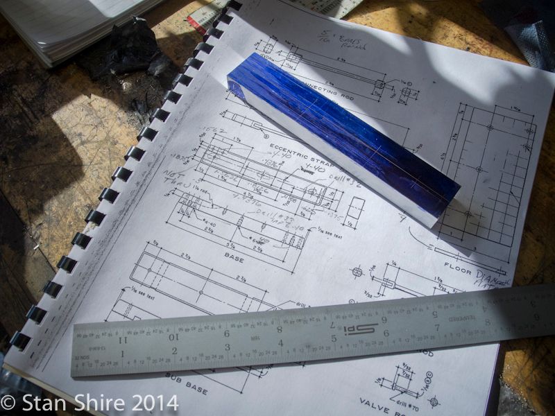
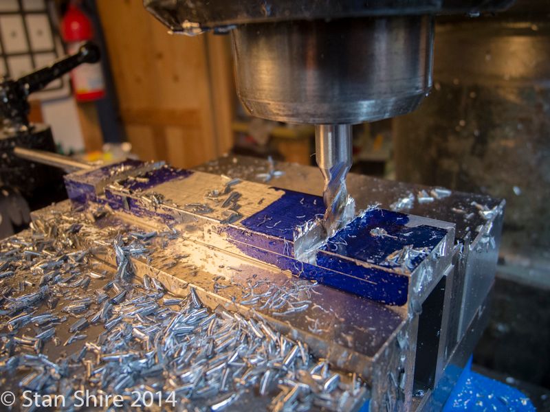
I usually build from the base up, so the base and sub base are first up. Dykem’d (is that a word?) and marked out. My usual M.O. to prevent mental lapses.


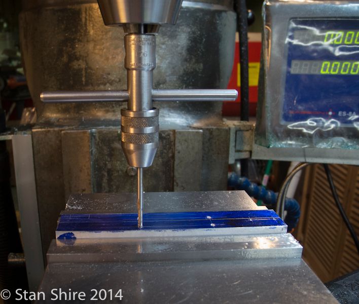
Spot drilling, drilling and tapping followed. When I can, I’ve been using spiral point or spiral flute taps for small holes. Less chance of the chip binding the tap.


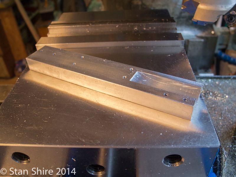
So the base has all of the holes done. So then, I’m looking at the plans and I see this.


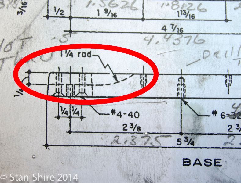
A radiused slot??? I can usually figure out some way to do things but this one had me stumped. I’m quite sure that everyone knows how to do this but me. I was just about to post a “How do I do this?” question on the forum when I thought about the shape and my slotting saws. Now, my thickest saw if .06” so that’s not going to work, but, a 2.5” x .5” one would give me the width and the 1.25” radius.
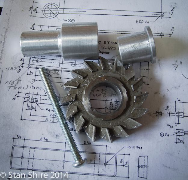
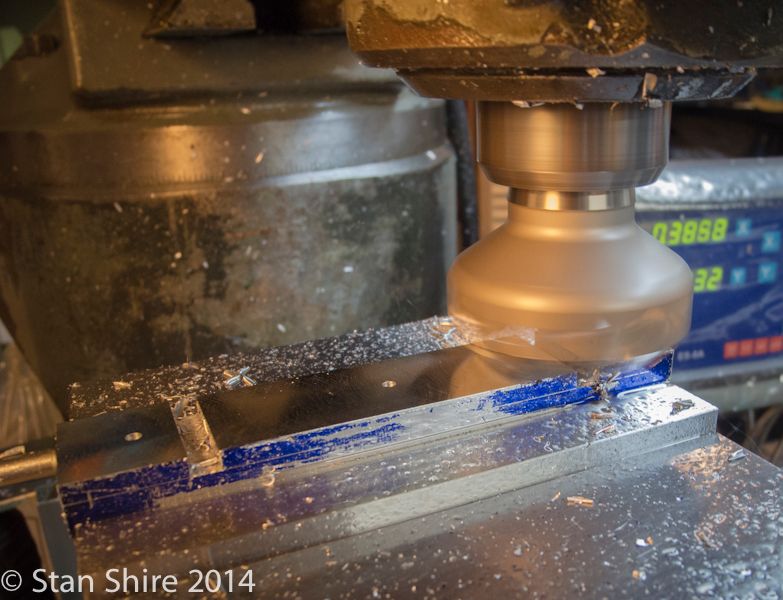
Ordered and received 2 days later. No way was I going to buy a $75 mandrel. I’ve made mandrels for my slotting saws. I had some 7075 1.125 round bar and made this.


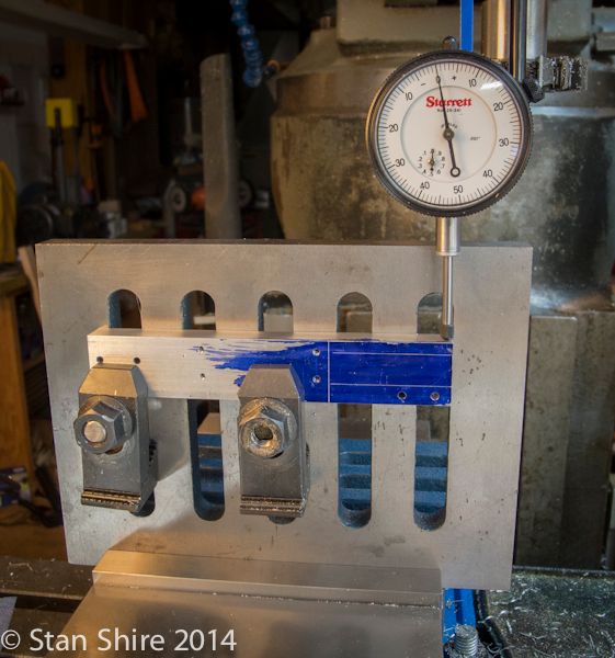
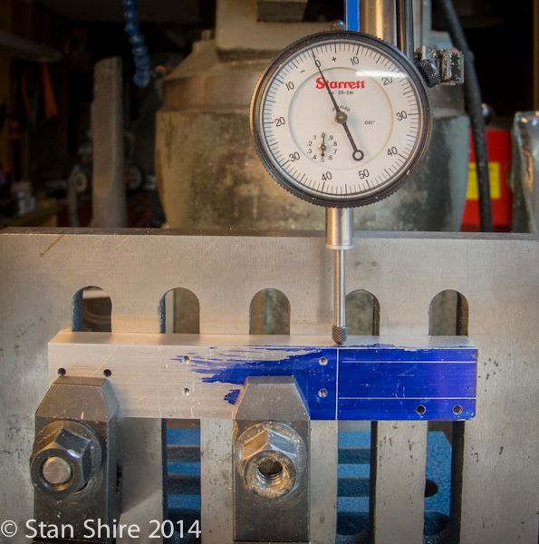
Since I have the headroom and I hate indicating the vise, I clamped an angle plate in the vise.
After some adjustments (%#*&*&&#!!), I got the part level enough.


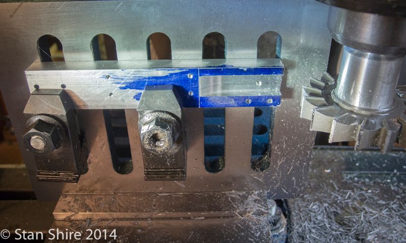
With the Bridgeport in back gear and light cuts, I got my radiuses slot with a nice finish.


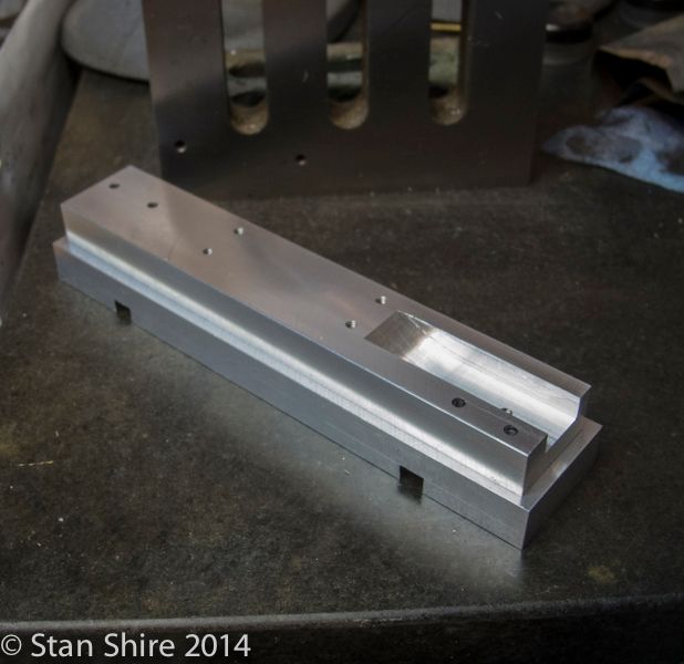
Then the sub base. Nothing but some drilling, two ¼” slots and a run with the face mill.


The first two parts done.


Pull up a chair. The fun never ends.
 
Great start Stan. I look forward to following another of your excellent build logs.
 
Hey Chris
No time to slow down.


Sent from my iPhone using Model Engines
 
Stan - you are the man, thanks for bringing us something else! My breath is baited :)
 
What do you use for breath bait, 'cuz I gotta catch mine. Ba dum bump.


Sent from my iPad using Model Engines
 
Elmer’s #33 - Mill Engine
Episode 2
Crosshead Guides


By now, if you’ve followed any of my builds, you know my feelings about Elmer’s sense of design. Not his engineering design, but his “every part is square” design.

Looking over the plans, I thought about an idea for the crosshead guides. My feelings are that I’ll try an idea and if it works - excellent! If not - it’s another small piece of metal to add to the “not quite right” box.

After laying out both (identical parts) on a piece of brass, I had to clamp it up like this. If it started to chatter, I’d lay it out on a larger piece and clamp it to the plate that I used a lot in the Cross Twin build.
Amazingly, no chatter and a good finish.


I did the layout so I could flip the part to machine the second copy. Butted the part against the stop, machined one part, flip, machined the other end.


I had laid out the part on a wider piece of brass so I could plunge and have support on both sides of the end mill. It seemed like a good idea.


Then ran the end mill in to remove the middle. This is the result.


Then Fettling with Oliver with a flat file and then a thin round one.


Then, both parts milled to length and to the correct height and then drilled.


Then back to Oliver to round the ends.


.1875” spacers parted off.


Here are all of the parts for the crosshead guides.


Assembled with temporary nuts and long studs. (4.5 threads above the nut.:D) Standard 4-40 nuts are too wide so I’ve got to make some that fit the guides better. The alternative is to remake the top plates a bit wider to fit the nuts.
All suggestions are welcome.

 
Looking great Stan. Keep those photos coming.
 
Herbie
I'll keep the pix coming if you come up here and take some of this damn snow back with you.
 
American Model Engineering sells scale nuts that look much better. I think I have some 4-40 nuts from them. PM me your address and I'll mail you a few (they're steel not brass).
 
I'd love to Stan. But with 40C predicted for Saturday how do I keep the darn stuff from melting :hDe:
 
Elmer’s #33 - Mill Engine
Episode 3
Cylinder and Fun With Centering


A piece of 1”x1” 6061 aluminum on its way to becoming a cylinder.


The cylinder bore is not at .5” in the 1” block. It is positioned .4688” from two adjacent edges. All set up here for step drilling and boring.


I learned from Bogs to bore with the knee power feed. I set the speed pretty low and get a very nice finish. Kept squirting WD40 at the reamer.


Entered the info for the bolt hole circle into the DRO and spotted, drilled and tapped.


I’m using a form tap for small holes. No chips means I don’t have to back out to break chips and haven’t broken any 0-80, 1-72 or 2-56 taps this way.


Now, here’s where the fun began. I was about to flip the part and setup for the opposite bolt hole circle and noticed that the circle was very slightly offset from the bore. Thus began the Great Centering episode.


I put the part back and recentered it with the Blake. Then I replaced the Blake with a DTI and swept the bore. It was off center by .024”
Then I proceeded to center with the Starrett center finder and the Haimer Zero Master. All were off and by different amounts. Same R8 collet.
I was out of ideas and nothing, in my vast 2.5 years of experience helped.
I posted the problem and, very quickly, Tony (ncmachinist62) came up with the solution. The Bridgeport was out of tram front to back. If you’re not familiar with the BP, the head tilts left and right and also “nods” front to back.
A BIG thanks to Tony for saving me on this one.

You can read all about it here:
http://www.homemodelenginemachinist.com/f26/centering-help-needed-22661/

The part was just long enough to mill off the offending end, repeat the previous ops and continue.

Drilling for the standard Verburg port face.


The stubby (.125 depth of cut) .0625” end mill for making the slots.


Setup in the sine vise for drilling the 16.5 degree ports. I found this neat sine bar/vise calculator at Little Machine Shop. Just enter the distance between the sine vise bars and the angle. Not only does it give the height of the Jo blocks, it tells you which blocks to use.

https://www.littlemachineshop.com/mobile/sine_bar.php


More tomorrow.
 
Elmer’s #33 - Mill Engine
Episode 4
More Cylinder Fun


This cylinder has more operations than a free liposuction clinic near a McDonald’s.

The angled ports have a 1/16” slot milled to provide a starting flat for the drill bit. Once again, the stubby end mill gets some work.


Im assuming the setup in the sine vise was correct since the bit exited in the slot port. A good thing.


24 holes and 4 slots later, we end up with this.


Now the cylinder goes onto the lathe to turn the ends round. I’m using a 5C expansion collet.


Turning the .250 deep round part of the cylinder.


Then turn it around and repeat for the other end.


Then the two sides that have had no ops, get their chance. Milling to the line.


With that done, it’s now time to round the corner. I suspended the part on a .500 rod and kept rotating and cutting.


Roughed out here.


Followed by Oliver, fettling and abrasive paper


Done and set in place.


Haven’t decided which part to start tomorrow. Stay tuned for another fascinating episode.
 
Looking good Stan.
 
Elmer’s #33 - Mill Engine
Episode 5
A Bearing Experiment


I really, really didn’t want to set up the rotary table to do the rounded tops of the two bearing towers., Not only that, but I have a tendency to overshoot with the rotab rotation and then I have to mill more off the flats. These are standard, Verburg design bearing towers and are used on most of his engines.


After thinking about this for a while I hit on an alternate method. I’m sure I’m not the first person to think of this, but if I am, send royalties via PM.
Not sure if this would work; I plowed ahead.

The drawing shows a 9/32” ( .2812” ) radius for the round top, I turned a piece of 6061 down to .5625” O.D. I’m calling this the insert.


After milling a piece that was slightly thicker than the finished size to the correct width, A .500 hole was drilled.


And then bored to a thou or so under the insert diameter.


Next, I removed material to equal the distance the round top projects above the flats.


Here’s the insert ready for the arbor press.


Good so far. This may actually work.


2” face mill ready to go.


There’s one pass. Now to flip it over and mill to correct thickness.


There are times when I amaze myself.


This is the other (larger) tower. I decided to use a .500” end mill to make the hole and bore an interrupted cut. That worked fine.


The second bearing tower ready for the mill.


I’m sure I’ll hear that there is some obscure 19th Century engine builder who made his bearings this way. Much to the delight of his competitors.

This will be my standard procedure for making these rounded tops as they are the best ones I’ve done to date. It also occurred to me that I could have used a brass insert or a Delrin insert or …..
 
Good trick Stan.
As popular as Elmer's engines are I am sure that it will be imitated many times.
Gail in NM
 
As always - fantastic work!! I wonder if a bench grinder could be used to round off corners like that in the absence of an oliver?
 
Heff
I see two issues with the grinder.
1. The spacing on this cylinder between the round ends is, IIRC, .825.
If the width of the wheel is less than this then that wiill work.
2. The bigger issue is aluminum loading the wheel. Pretty sure it would clog up quickly.

The rough rounding on the mill didn't leave all that much work to finish. Files would work pretty quickly and are easily unclogged, especially if they are chalked first.
 
Really nice work as always Stan. That was a neat trick making the rounded tower tops. I've got to file that one for sure (no pun):p

Cheers,
Phil
 
Back
Top