Elmer’s Mill Engine #33 build - MZT

Home Model Engine Machinist Forum

Help Support Home Model Engine Machinist Forum:

This site may earn a commission from merchant affiliate links, including eBay, Amazon, and others.

mzetati

Well-Known Member
Joined
Dec 2, 2010
Messages
236
Reaction score
6

The Floor and Bases
Made them long time ago, no pictures were taken.
Milled them to size from various offcuts taken from the scrap pile, then drilled all the holes using the DRO.
Bevelling will be the last operation, after checking all parts are fitting OK.

The cylinder
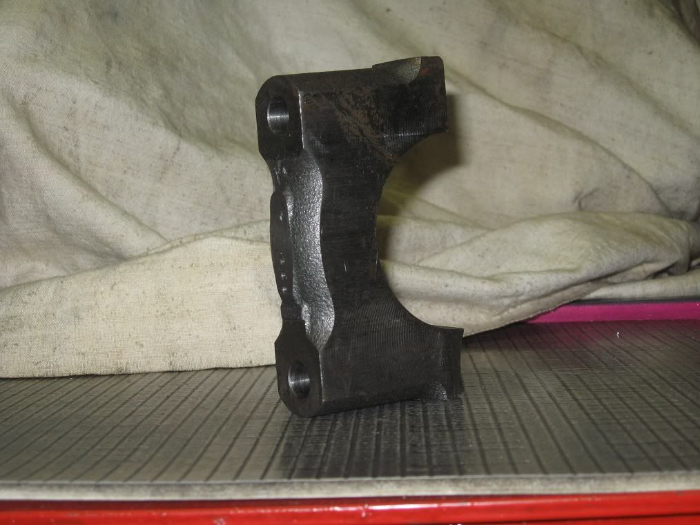
A friend of mine brought me this partially machined con-rod cap from work: the drill obviously wandered and the item had to be discarded. That’s cast-iron of the finest grade!!! And there’s enough

material to make 3 cylinders.

01Cyl_IMG_1994.jpg


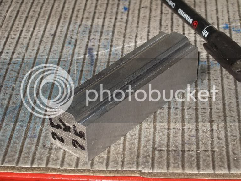
After a quick (so to say) session with the hacksaw I’ve got the blanks to start working on.

01Cyl_IMG_1995.jpg


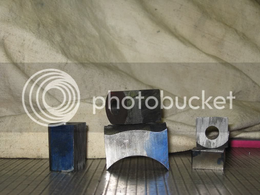
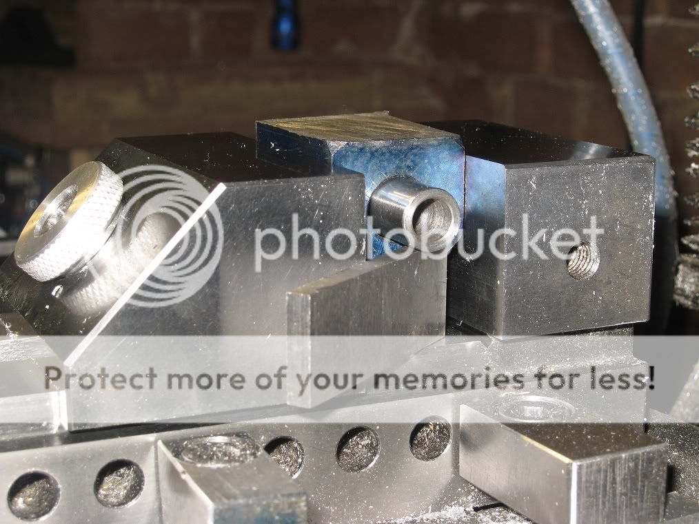
1st step: I secured the material into the vice, suspended on two spacers and a rod through the bore, to mill a face reasonably parallel with the bore axis.

01Cyl_IMG_1997.jpg


2nd / 3rd step: (no pictures taken) The recently milled face was put against the fixed jaw of the vice, and the same method as before applied to mill a second face, square to the first and (again)

reasonably parallel to the bore.

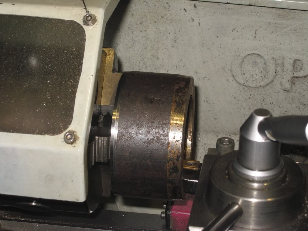
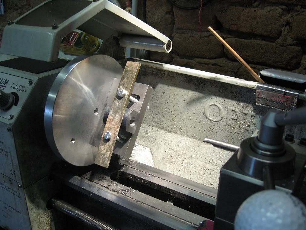
4th step: now on the lathe faceplate, making use of the two surfaces at right angle to face one end of the cylinder and machining the bore.

01Cyl_IMG_1999.jpg


Steps 5, 6, 7, ... n: OK, I messed up!
When I dismounted the cylinder, all would have been OK if only I had not forgotten to make several passes with the boring bar on the final cut, to for the springiness of the tool. Took a final heavy

cut, instead, to improve the finish.
(Yep! Finish was definitely better on heavy cuts than on shallow ones)
Results were a noticeable taper into the bore, too evident to correct in any way but machining again.
(Stopped taking pictures for a while, at this point).
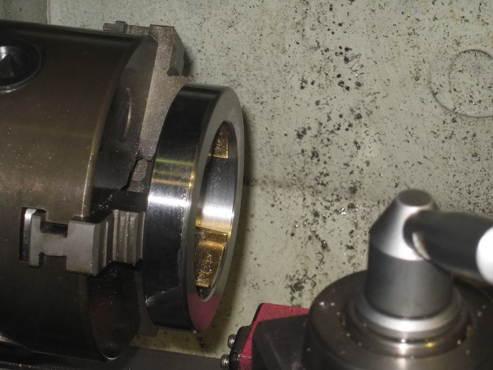
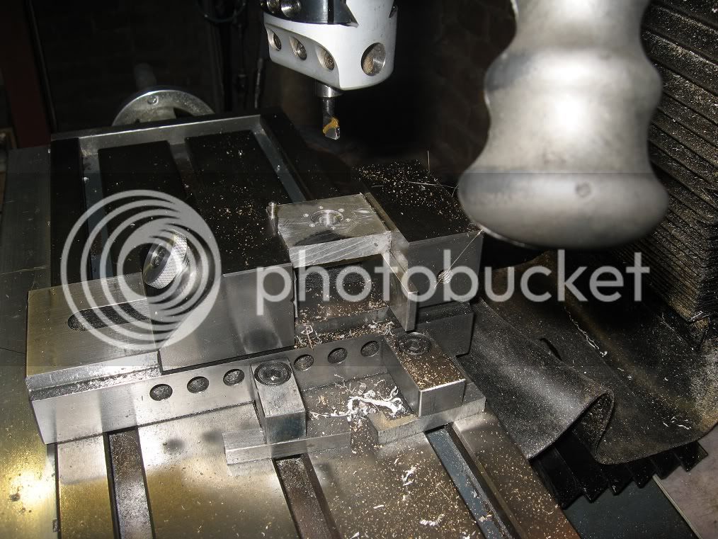
The cylinder was mounted vertical into the mill vise, checked for trueness and centred with a DTI and then bored to a cylindrical shape with a carbide tipped bar into the boring head. – Several “last

passes” were not forgotten, in this occasion.

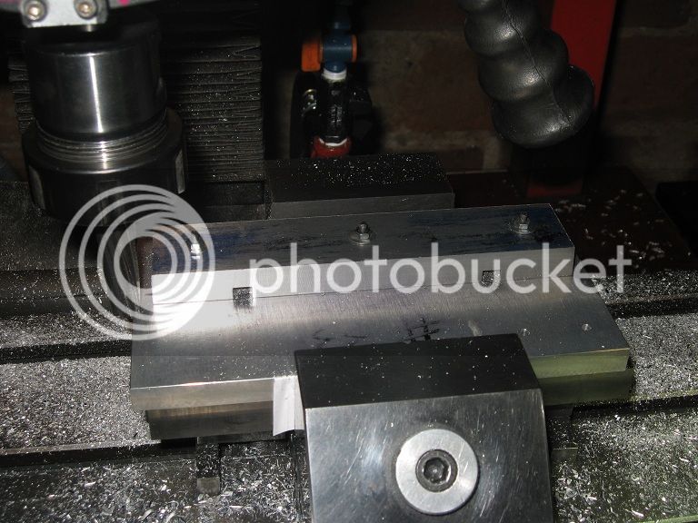
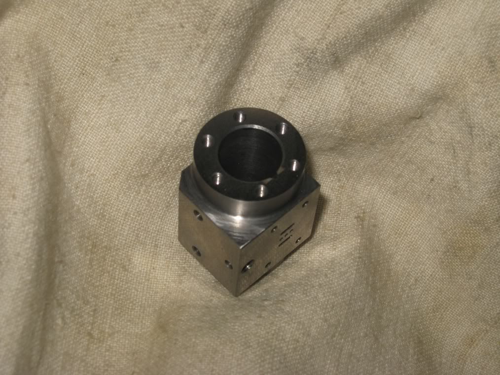
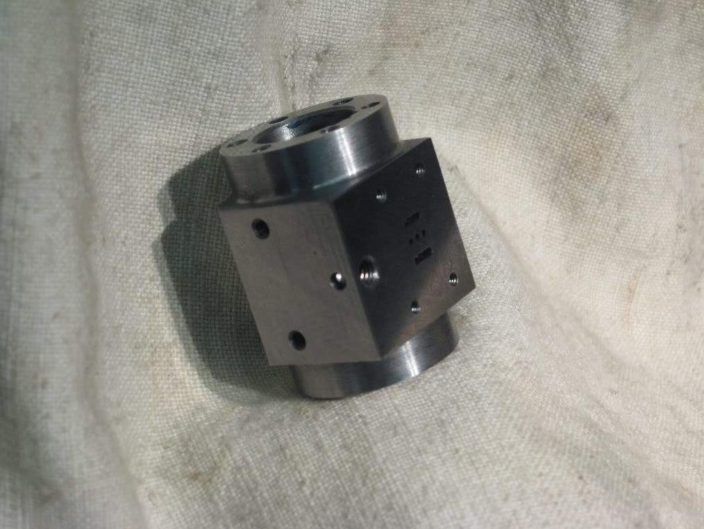
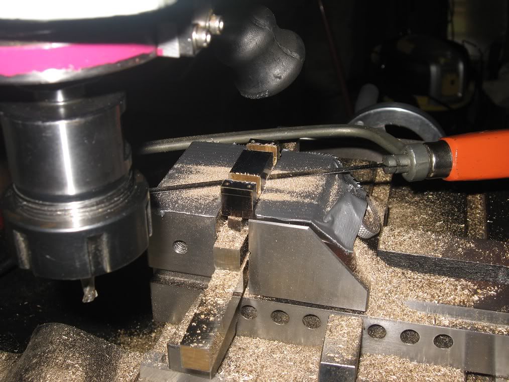
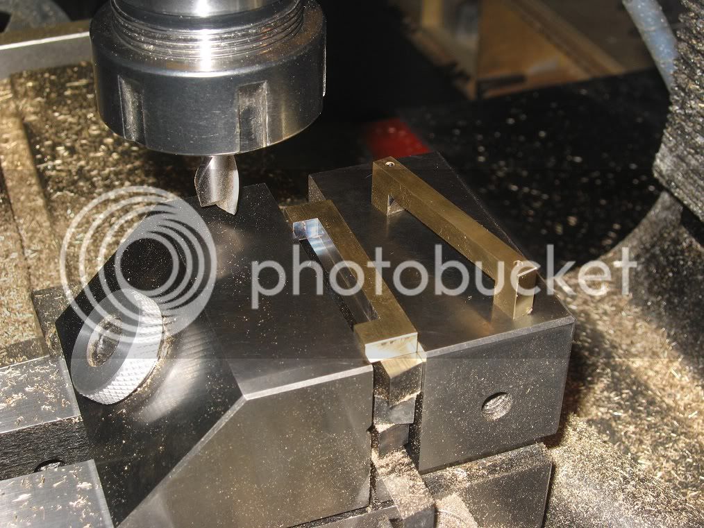
Step n+1: some more work on the mill to bring the external dimensions of the cylinder to size, taking reference from the bore. With the material finally squared and brought to size, I drilled all the

passages, the holes for the holding screws and milled the slots for the steam.

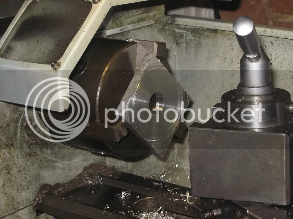
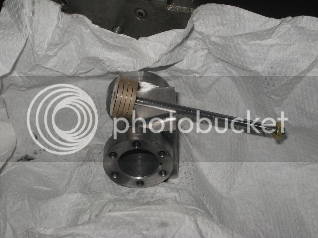
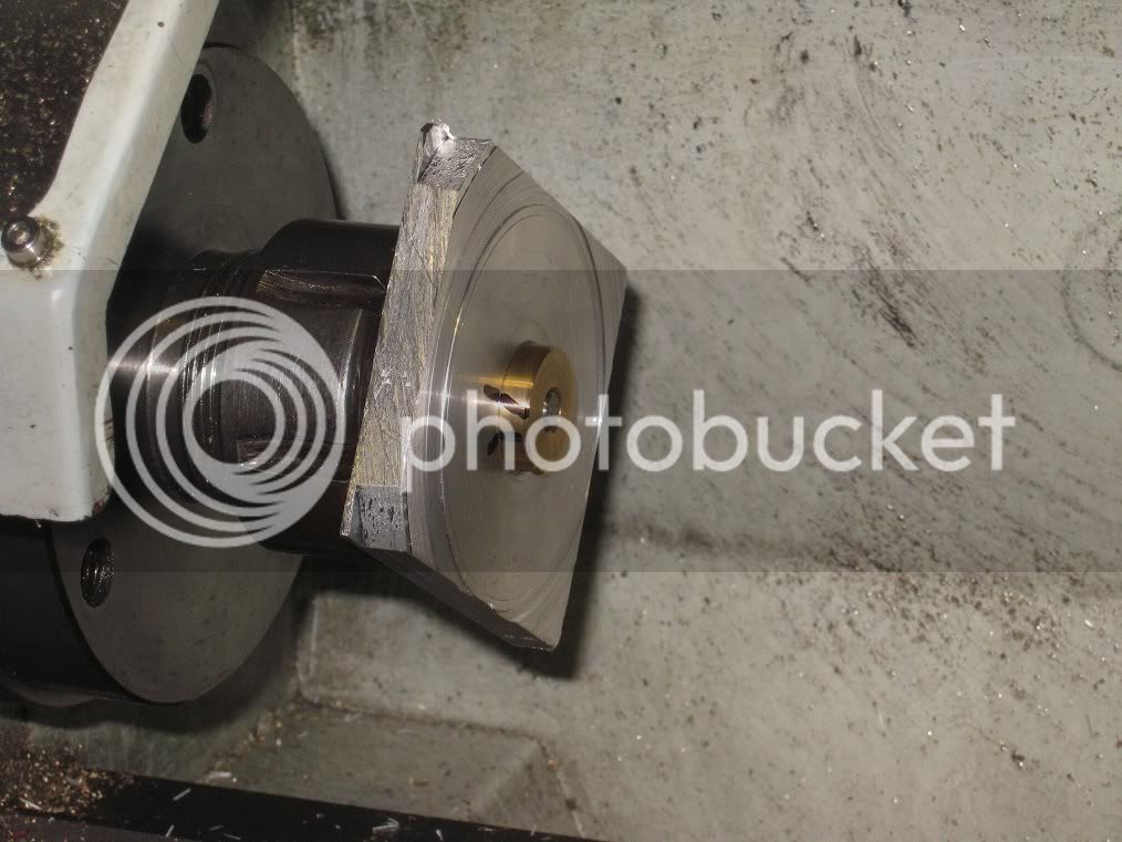
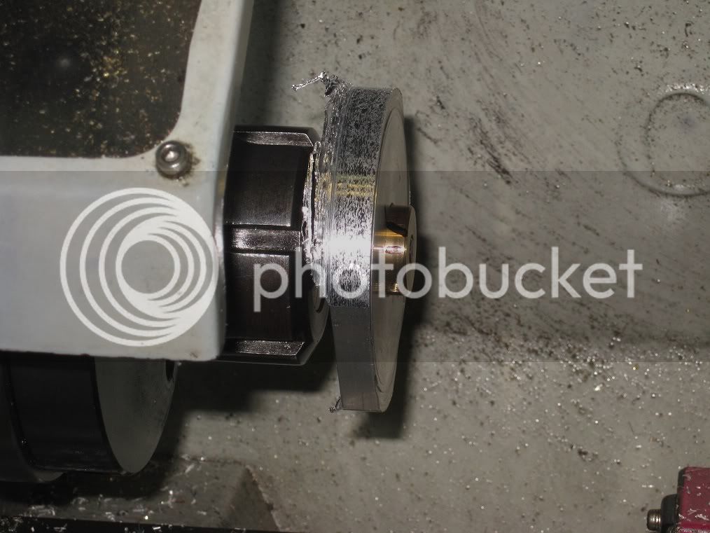
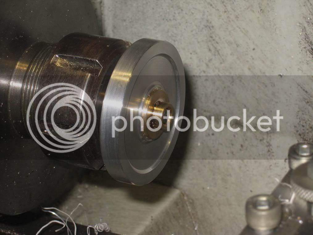
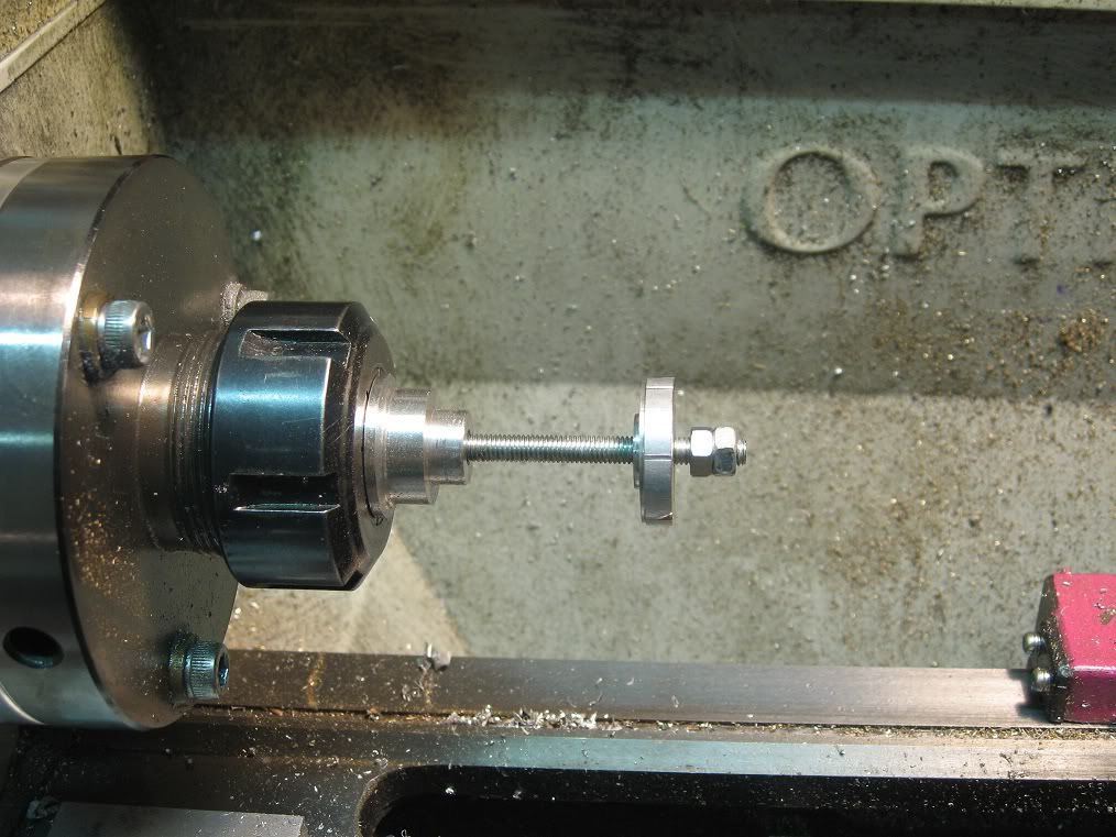
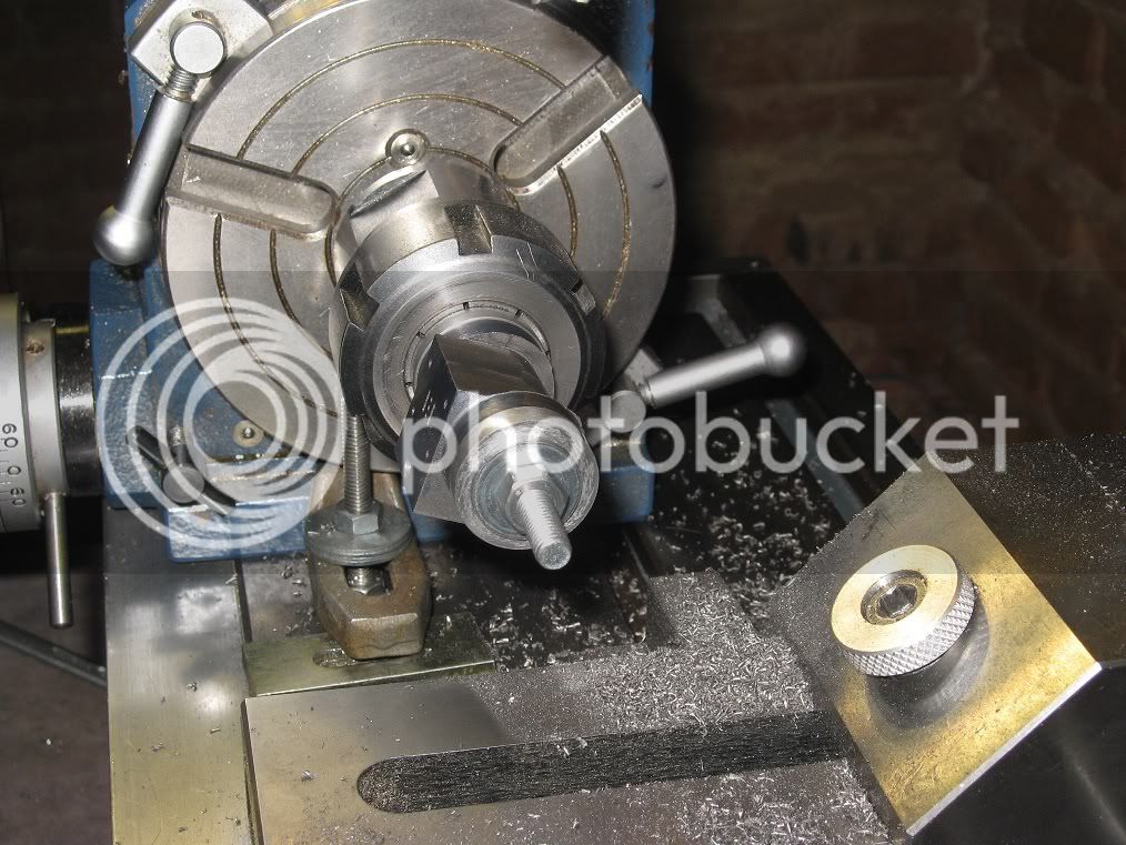
Step n+2: after machining a mandrel + cap to bore size, I mounted the cylinder on the lathe spindle to turn round the upper and lower portions. (the next two pictures show the mandrel and cylinder I

had made while building #29, same principle applies)

02Cyl_IMG_1630.jpg


02Cyl_IMG_1632.jpg


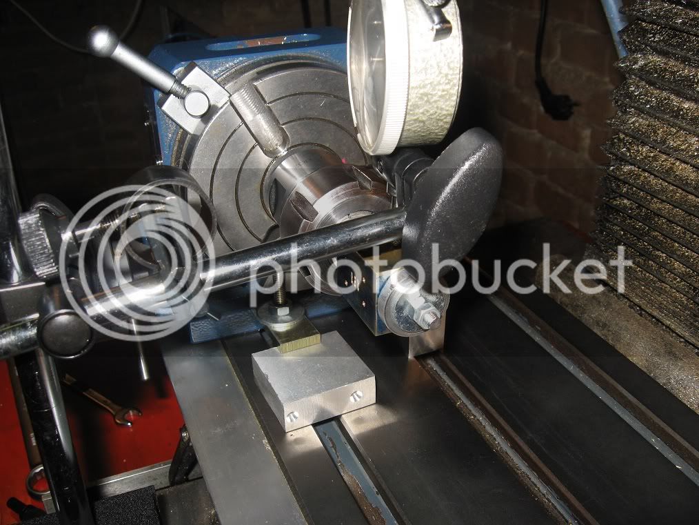
Step n+3: the mandrel assembly was then transferred to the rotary table (picture shows the mill ER32 collets holder I used) to be milled and rounded in the central part.

03Cyl_IMG_2003.jpg


03Cyl_IMG_2005.jpg


03Cyl_IMG_2011.jpg


The Heads

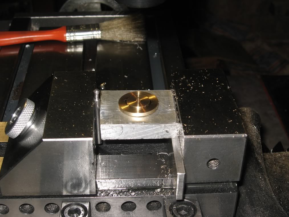
Chucked a small brass rod into the lathe, faced and turned it to size. Zeroed the adjustable carriage stop and took a light facing cut, then moved the micrometer 9/10mm to the left to machine the

portion to fit the cylinder diameter, then parted off the outboard head. (The remaining pip was removed with pliers, file and sandpaper).
The inboard head was made by machining the external part first, then reversed into a collet to make the hidden portion.
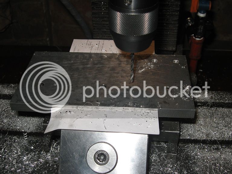
Drilling the hole was a slower job: first of all, I set a piece of scrap al. Into the vice, zeroing the DRO roughly in the center. Then I drilled a hole to fit the outer head

03Cyl_IMG_2017.jpg


Inserted the head (reversed) and drilled the holes at coordinates (the DRO helped a lot into that!)

03Cyl_IMG_2018.jpg


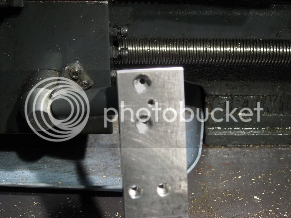
The outboard head was held through enlarging the hole with the aid of a boring head till it was large enough to accept the head in its ‘normal’ position. Had some issues regarding the head possibly

moving during the drilling operations, so I held it in place using some paper tape.

03Cyl_IMG_2019.jpg


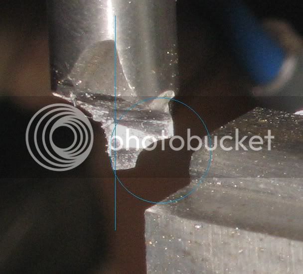
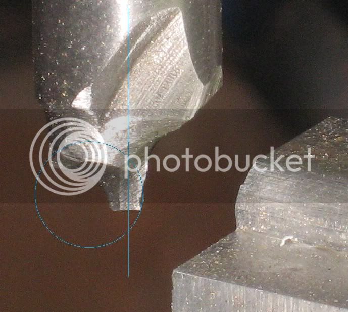
Was right about the issues, not so about preventing the head from moving: when the centre bit grabbed on the third hole...
Fortunately, the head was not ruined: at that point I drilled the plate through, and used a screw and nut to keep the head in place. Then drilled a diametrically opposed hole for a second screw.
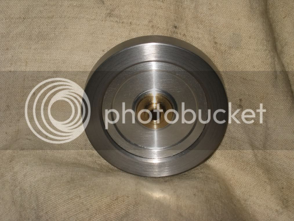
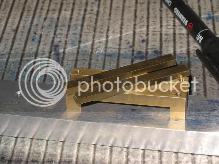
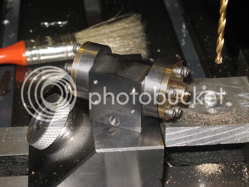
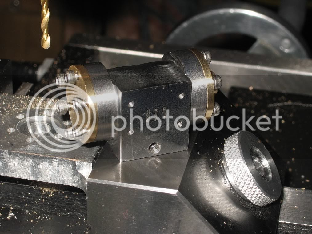
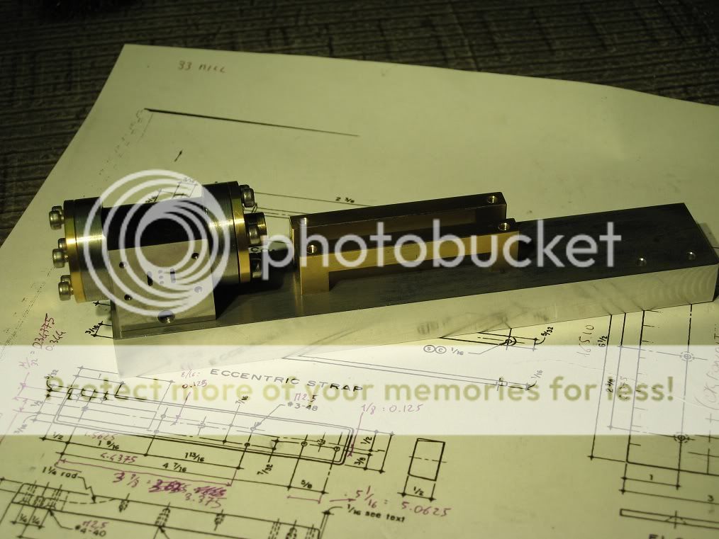
Here’s a coupla picts of the cylinder, complete with the heads.

03Cyl_IMG_2020.jpg


03Cyl_IMG_2023.jpg


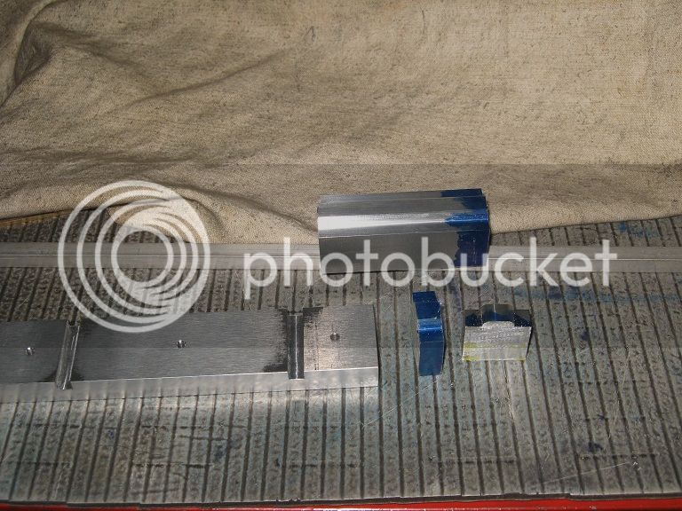
The Crosshead Guides

Sawing part of the unneeded material, I will find some use for that.

04CH_IMG_2091.jpg


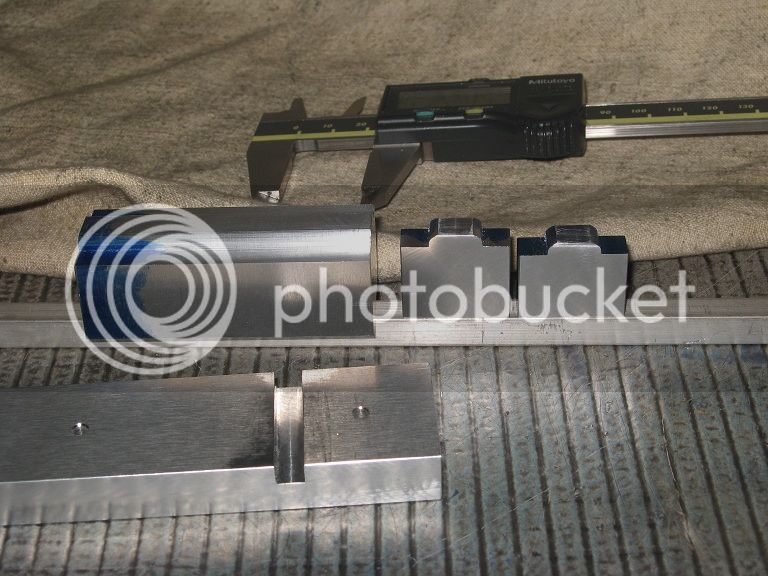
Next, I milled the part to size and a decent finish marked it, and finally cut it. Here they’re shown after the final milling on the parting line.

04CH_IMG_2093.jpg


The Piston shaft won’t line with the guides!

While test fitting the cylinder ,crosshead guides and a temporary piston shaft on the base, I had the unpleasant vision of a piston shaft unequally spaced among the guides, because the two fixing

holes on the bottom of the cylinder were misplaced. Chose the easy way of re-drilling the holes on the base.

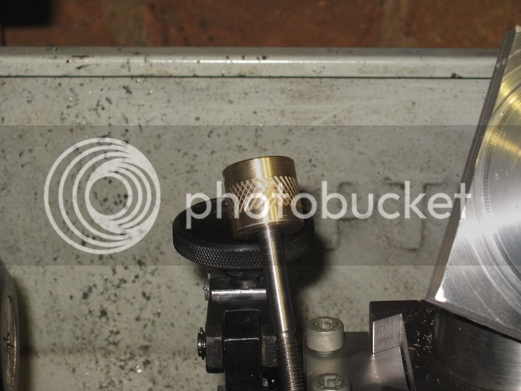
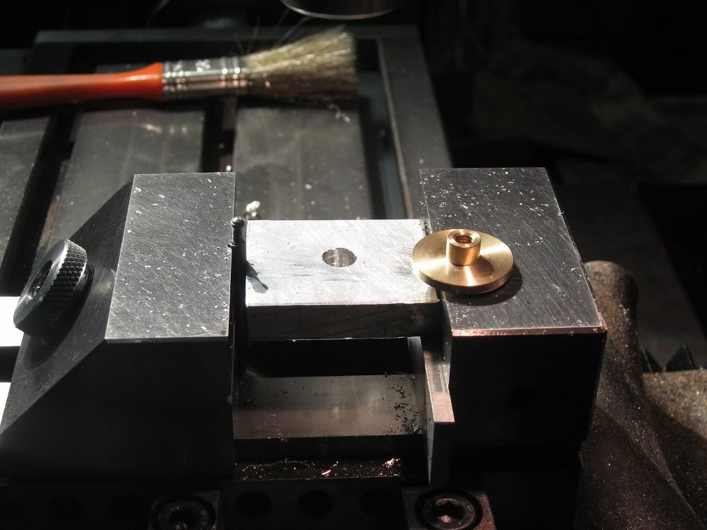
First of all, I need to fill the voids: here, i’m machining a 3mm screw from a short rod of gummy al.
Not such a good thread, but hopefully thread locker will aid.
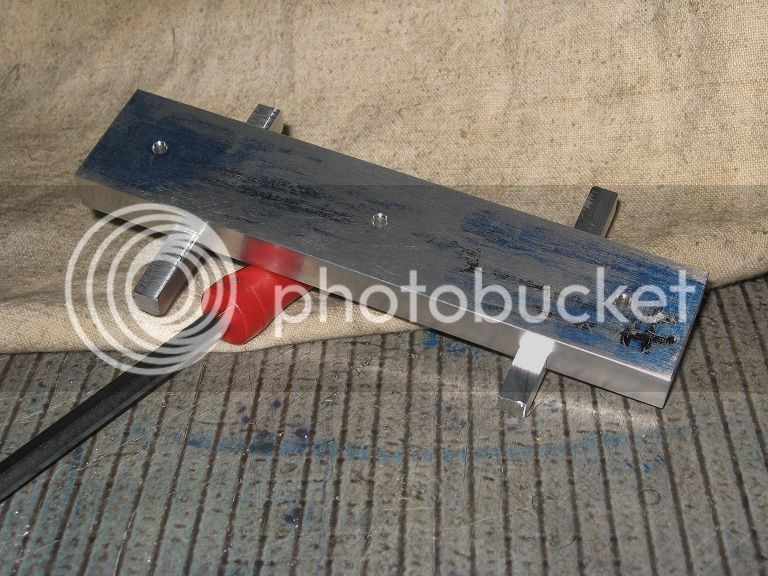
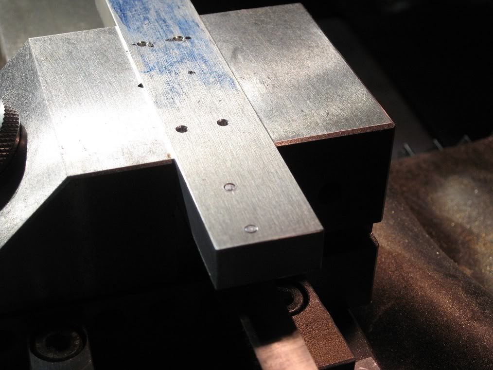
In the background, the base evidencing the two holes I need to move.

05CHFix_IMG_2102.jpg


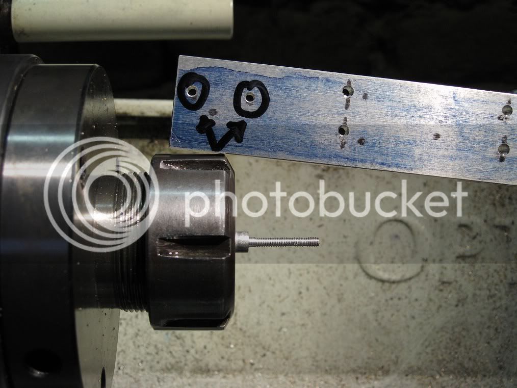
Barely visible, the two holes already filled. Now i’m ready for re-drilling them in a more suitable position.

05CHFix_IMG_2108.jpg


Had to enlarge the coutersinks on the bottm side. Sure, this piece has evidence of poor craftmanship.
But they will be hidden, and no one will ever see them..

05CHFix_IMG_2111.jpg


Things are much better aligned, now.

05CHFix_IMG_2115.jpg


Marcello
 
Great work!! ;D

The surface finish is excellent!!
Looking forward to following this build!

Andrew
 
Looking good. Thanks for showing us the little goof-ups. I feel much better now ;)
 
Flywheel
Here’s the blank: a 72mm thick walled steel tubing from the scrapyard.

06FW_IMG_0214.jpg


Turned on the outside (with no attention to the finish), bored to whatever diameter it came, faced, parted and re-faced on the second side.

06FW_IMG_0217.jpg


A small aluminium plate held in the 3jaws for facing and drilling a hole in it. That’ll be the blank for the flywheel webs, I do not yet know what shape I will make them.

06FW_IMG_0219.jpg


Next, I turned, drilled and reamed a small brass rod to accept the flywheel shaft, to be press fitted into the webs blank. Got a push fit, not enough secure for my tastes.
I set the hub on a temporary shaft to knurl its central part, then wetted it with loctite and repressed into the al.
That should do, will know for sure tomorrow.

06FW_IMG_0223.jpg


Piston and piston rod
Having been forced to let the flywheel aside till the loctite is set, I turned a piston out of the tiniest piece of bronze I had: did not have to remove much material to get it to size.
First of all, i cut and threaded the piston rod ends, then chucked the piston blank in a collet and turned it .5mm oversize. Next, I drilled the tapping and clearance hole for the 3mm shaft, screwed in the rod (with a bit of loctite, as it was still at hand from the previous job), re-chucked the shaft in a 3mm collet and brought the piston to push size.
That should ensure the piston and piston rod are exactly on the same line.
The picture shows the piston and cylinder after the final lapping using very thin polishing compound and oil.

07Ptn_IMG_0226.jpg


Marcello

 
This will be one of my next projects. Thanks for the great pictures and descriptions. The main cap used for material for the cylinder is a great idea. Very nice machine work. I'm looking forward to following this build.
 
so, "main cap" would be the name for my 'con-rod' cap, I guess... :)
Definitely first quality cast iron in it. And if You can find one with holes drilled straight, that would be even better.
Someday, I will pay a visit to some car repairer, maybe a truck repairer or two while I am at it. ;D ;D

Marcello

 
Just to clarify----A "main cap" holds the crankshaft in place in the engine block. It is actually a "Main bearing cap". A connecting rod cap is the bolt on end of a connecting rod.
 
Keep going! I love Elmer's engines!!!

Chris
 
The Flywheel (continued)

An initial deep (5mm) cut showed no signs of motion among the loctited parts: rather have them split now than on the final cut, :)

08FW_IMG_0241.jpg


Roughing cuts: the finish is ugly. Hopefully a round nosed tool when I will get to the sizing cuts will do better.

08FW_IMG_0242.jpg


It did.


08FW_IMG_0244.jpg


After pressing the tyre, I had the (bad) idea of mounting the wheel on a 6mm arbour and spin it in the lathe for a final truing: got chatter, tremendous! Like waves on the sea (in a windy day).
I should have take a picture of it.
Dull tool? Mounted another, same results.
Speed up? Slow down? Skin cuts? Deep? ....? ...?
Answer was always CHATTER! CHATTER! CHATTER! !!!

08FW_IMG_0247.jpg


Then, it occurred to me the wheel was mounted on a 6mm silver steel arbour... and if it were due to springiness on the arbour ?
When I mounted the wheel hub into a 19mm collet, however short the grip was, the chatter disappeared.

Marcello


How did you find the retract stroke on the cylinder after you finished the valve? Does it work okay, and does it have the same (or close to the same) strength as the extend stroke? I'm using the same valve set-up on an engine I'm building, and running into difficulties with the retract stroke.
 
After pressing the tyre, I had the (bad) idea of mounting the wheel on a 6mm arbour and spin it in the lathe for a final truing: got chatter, tremendous! Like waves on the sea (in a windy day).
I should have take a picture of it.
Dull tool? Mounted another, same results.
Speed up? Slow down? Skin cuts? Deep? ....? ...?
Answer was always CHATTER! CHATTER! CHATTER! !!!

There is your problem, the wheel needs to be well supported to stop chatter - a 6mm arbour will not give that!
 
tel said:
There is your problem, the wheel needs to be well supported to stop chatter - a 6mm arbour will not give that!

Yep! Lesson learnt!
And a 12mm HSS bar leads to identically bad results (Bernay thread).
(They will go on the faceplate, someday).

Marcello
 

The Bearings

A bit of progress on this long forgotten project: last Saturday I got around making the bearings; while I was at them, I decided to make a few, just in case I will get interested into building another engine from the book. <G>
Started with squaring a block of aluminium, then centring the cutter and milling the sides to depth; when it came to rounding the edges I decided to make an experiment into grinding a cutter right for the job.


09_IMG_0490.jpg


Started with a 10mm 2 fluted end mill who had seen too many resharpenings (only a few mm of flutes were left) and ground away one of them [==> single cutter, so I won’t have to make two cutting edges alike].

A few minutes of hand grinding on the bench wheel (and many more toying myself with diamond files and oil stones) gave this result

10p_IMG_0485.jpg


10p_IMG_0487.jpg


Had a little more shop time to spend (not enough to complete the bearings) so I decided to use it making some of the missing parts for the crosshead guides, hacksawing and polishing them from a 3mm brass plate.
It was already late at night: I left the drilling for the next day...

11_IMG_0488.jpg


..being well aware the next morning I’d have picked up another project.


Marcello
 
Looking good Marcello!!! ;D
Keep it up and it will be done in no time!

Andrew
 
Lovely work Marcello.

I really enjoy seeing little engines appear out of bits of scrap material rather than rushing out and buying raw stock, just like I like to do it.

The layout of your build is really good as well, big pictures that I can see, and text mixed in with the pictures, you know what is happening when it is done that way.

Very well done indeed


John
 
Hey Marcello.
How is this build going?
Looks good so far.

Plus another blatent chance to put up another drawing. :D :D :D

ISO.jpg


ISO 2.jpg
 
Going ? Definitely slowly.
I don't need this engine being brough to completion before I'm finished with the Bernay (maybe both of them, not yet clear ideas).
Soon after, tho.

Marcello
 

Small works on Bearings, Base and Lugs

I’m only working on this engine at random intervals, whenever I’ve no time or interest into working on parts
for other engines and no new project gets in the way.
Gotta push this one too, if I want to bring it to an end.

Having recently shaped a long bearing block, I cut two portions of it, gave them a decent finish using a
flycutter and sized one to the correct height.

12_IMG_0771.jpg


The taller one is already too short, I knew: will look for some way of putting a bit of metal where it should be.

12_IMG_0773.jpg


A second look at the slots I had cut into the base to accept the lugs revealed all the damages I had done while
trying to bring them to a better finish through improper hand use of machine tools & desktop accessories.

Had to cut them once more in the mill, deeper and larger.
Next I roughed the lugs, from some 10mm gummy square, still longer and thicker than needed.
Will have to bring the base to the desired finish before fitting them in place, should I opt for a permanent mount.

12_IMG_0777.jpg


Marcello
 
Reaming a bevel

I temporarily mounted the sub-base to the floor, set them flat into the vice on parallels and chucked the
largest taper reamer I could find into the ‘tools purchased by weight’ drawer.
I had more concerns about ruining the workpiece than about the reamer: that one, together with most of the others,
has been laying there for years, unused. I’ve never been in need to ream a hole to an unknown taper, and
I don’t think I will be likely to face such a task in the near future.

13_IMG_0785.jpg


In the end, I got the job done in seconds, and the reamer suffered no visible harm.
The bevel is shallow, but clearly noticeable. A bit of sandpaper work on the plate should bring the item to a decent finish.

Before dismounting the sub-base, I drilled a couple (three, to be exact. But the third one I’m trying to forget..)
of extra holes through both the items using a 2.9mm bit. That made holes exactly the size of a 3mm bit shank:
they should aid re-aligning the base with the floor on subsequent mountings and dismountings.

13_IMG_0788.jpg


Marcello
 

Small bevelling progress, no pics.

Spent (quite) a few minutes reaming a bevel on the top base using a different reamer, one which was slightly more tapered, from the same scrap pile.
Gotta buy myself a tilting vice, someday.
I made use of the aligning holes I had put on the floor and base to have them aligned, then placed three washers between the assembly and
the top base, to gain some working clearance.

At the end of the job, I decided to deepen the aligning holes into the top base: cannot say how, I managed to clog a 2.9mm drill bit into aluminium,
while deepening the second hole to an extra 5mm. Unusual clog, btw: the bit could turn, but no way I could get it out.
Got it back again, after dismounting, but I don’t think them holes will be any good for the purpose I had put them in.

Had to swallow it: it was not going to be a good machining day.
Rather shut off the machines and look for some hand work: removing tool marks and polishing the bases did, though it lasted much longer
than the “bit of work” I had estimated.
And aint close to the end, yet.

Marcello
 

Latest posts

Back
Top