DRO on the mill

Home Model Engine Machinist Forum

Help Support Home Model Engine Machinist Forum:

This site may earn a commission from merchant affiliate links, including eBay, Amazon, and others.

firebird

Well-Known Member
Joined
Oct 26, 2007
Messages
1,143
Reaction score
8
Hi

I've just spent the afternoon gainfully occupied fitting a DRO to my mill. Ive had the DRO's for about a year and finally got round to fitting one of them to the longtidudinal travel. My mill is a Sieg super X1L (in the colours of Axminster Power Tools) and has the optionanal long table fitted The main reason for doing this is my lathe (a Myford ML7) is imperial and the mill is metric. It gets a bit awkward when transfering parts from lathe to mill. Converting from imperial to metric and back again doesn't always work accurately and it's too easy to make a mistake. The DRO will switch between imperial and metric. Although I only fitted it this afternoon I can already see a huge benefit. Below are a few photos of how I did it. they should be fairly self explanatory but if anybody wants to know more just ask.

The brackets are made of 3mm steel.

DSC06228.jpg


And are fixed to the underside of the table with 4mm countersunk screws.

DSC06234.jpg


DSC06236.jpg


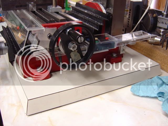
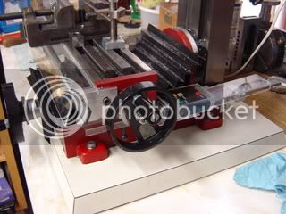
The table fitted back on the mill.

DSC06238.jpg


The DRO fitted to the brackets with 2 4mm screws.

DSC06241.jpg


DSC06240.jpg


The sliding part of the DRO is fixed to the cross slide with a 4mm screw.

DSC06242.jpg


DSC06245.jpg


I haven't figured out yet how to fix the DRO to the cross slide. Theres not a lot of room underneath and is of course obscured by the longtitudinal table. Has anyone out there carried out his mod and if so how did you do it?

Cheers
 
Hi FB,
I fitted 3 axis DRO's to my mill/drill many moons ago, unlike yours I use coolant so they couldn't be mounted as you have done.
My DRO's were mounted at the back and under the side with perspex anti splash covers, but because I couldn't see them I used a 3 axis display box designed for these cheapo linear scales, just plugged the leads in and mounted it where it could be seen.
You can see it on this post
http://freeforums4u.com/viewtopic.php?t=137&mforum=homemodelengine
They cost about £100 ($200). One of the main advantages is that you can control all three readouts from the box rather than having to fiddle round with the buttons on the DRO's themselves.

John
 
Hi

That seems like a good idea John I'll look into it.

PS
Do you know were I can get £100.00 from

Cheers
 
FB,
You can get individual ones for about £30.

But if you really want the 3 axis readout, sell the miller to raise the cash, problem solved.
Catch 22.

John
 
Hi

Thanks for the tip John. But what would I attach the DRO to?
 
Hi FB,
That is where the catch 22 comes in.
There is another way but it involves standing at a crossroads for a bit.

But this is what you really need for just one where you can't get to it.
You only have to sell your chair to get this one.

http://www.arceurotrade.co.uk/en-gb/dept_111.html#item_1078

There are also a couple of good accessories that can be made for digital calipers if you go up the page a bit.

John
 
Hi john

Thanks for that. That may be the answer as I already have the DRO scales and at 30 quid I could keep the chair

Cheers
 
Hi

I took the plunge and bought a DRO from Arc Euro Trade. It looks to be pretty good quality. I hope to have it fitted and working on Saturday so I will let you all know how I got on and post some more photos.

Cheers
 
FB,
When the original batteries run out, go down to the local car boot and pick up a small power supply and solder it in place of the battery holder, it will save pounds in the long run and also be more stable as they do get a bit slow when the batteries start to run down.
I found I also had to trim the plug that goes into the scale with a scalpel to get it to go all the way in and form a good bond with the pins, but yours just might have been modified since I had mine.

John
 
John...
There you go again using that colorful English language again, would you mind explaining to us over here what a "local car boot" is. I have an idea but I would rather here the official version.
By the way I made the Exhaust Pipe for my project today, pics at eleven, do you have another name for that, if so I could use it to impress my uneducated friends. :lol:
 
Jack,
I keep forgetting that we are being spied on by our colonial cousins.
'Car boot sale' is like your garage sale, only mobile. Usually on a sunday morning, local car parks and fields host a gathering of people, sometimes into the hundreds, with all their various bits of junk piled into the trunk of their cars. Sometimes real bargains can be had, but also a lot of the stuff is only fit for the dump.
With regards to your 'exhaust pipe', I will have to go and have a look before I pass comment.

John
 
Over here on this side of the pond, we call them FLEA Markets or if it is organized and held on regular basis they are called swap meets.
.
 
Jack,
We are getting away from the main topic of this post here, but I will answer this one because that bit of kit you have made there, looks the dog's dangly bits. Very, very, well done!!
BTW, we call it an exhaust pipe as well.

John
 
Firebird, may be you want to look at these pix

DSC00416.jpg

DSC00415.jpg

I just put them on a Mini Mill. Works great.
Hilmar
 
Hi

Thanks for those pics Hilmar, I have got to do something along those lines to mine as you will see from the following pics.

I carried on today fitting the DRO scaLE to the cross slide but immediately came across a problem. The mill is rated as having a cross slide travel of 145mm so when I bought the DRO scale I figured a 150mm DRO would be bang on. However the actual tavel is considerably more than 145mm? obviously exceeding the travel of the DRO. So that I couldn't accidently damage the DRO scale by over travelling the cross slide I have fitted an adjustable stop. Having fitted the scale and plugged the remote DRO in it was immediately obvious how good it was. The machine has been transformed. With that in mind when it came to making a fitting for the DRO (they are magnetic and stick to any steel surface) I made it big enough to take 2. The scale fitted to the longtitudinal slide will have to have one as well when funds will allow it. Perhaps Santa will be kind to me! The following pics are were we are to date.

Cheers

The fixed part of the stop

Drill and tap 4mm, fit a screw with a short length of brass tube.

DSC06246.jpg


The adjustable part of the stop.

3mm thick plate held to mill with 2 X 4mm screws. ! screw also holds end of DRO scale with brass spacer fitted. Short piece of drilled and tapped 10mm X 10mm steel brazed to plate and fitted with 4mm cap head and lock nut.

DSC06249.jpg


The DRO scale fitted.

DSC06255.jpg


The metal bracket for the DRO's is fabricated fom a 200mm length of steel tube, a 125mm X 125mm 1.5mm thick steel plate and a 50mm length of 12mm X 4mm and welded together. It is mounted onto one of the mill mounting bolts. Now I know it all works I will remove this mounting and give it a coat of black hammerite.

DSC06256-1.jpg


To protect the scales I have just cut 2 pieces of polythene and stuck them on with blue tak as a temporary measure. Now that I have senn Hilmar's method I will make something similar.

DSC06258.jpg


The LCD mounted on its bracket.

DSC06265.jpg


Job done.

DSC06262.jpg
 
Nice job there FB.
I started out with a couple of those small DRO units, but when I fitted one to the quill I had to go for the treble unit.
When you eventually get the cheapest one done, the quill, you will notice that everything gets a lot easier and much better accuracy can be achieved. In fact if I was doing it over again, the quill would be my first one, but you have to make sure the quill lock is spot on with a good grip. On my quill when I tightened up the clamp it put on another 0.1mm cut, but since I dressed the clamps inside to match the quill radius, it is spot on.

John
 
FB,
take your mounting brackets of and mount the scale on one side only as you see on mine . Look way on the right for the Y scale and front left for the
X scale. The other end is floating in free air. One bracket and the display will hold all together. This will take of slight miss alignment and you may gain what you need need in length.
If this is not working,buy a larger scale. You be better off. You will like it in the long run.

Hilmar
 
Hi

Thanks for the tip Hilmar. Has any one fitted a DRO to the quill fine feed on a mill like mine? I can see it would be fairly straight forward to fit one to the main column but would like one on the quill.

Cheers
 
Hi,

my Mill has no quill as yours. I can feed with the column only. Also I can't see your complete Mill in the pix but if the quill I see sticking out is not turning I see no problem.
HILMAR
 
FB,
JohnS has done this mod to his miller which is basically the same as yours. I do have a picture of it that he sent to me, but I wouldn't want to post it without his permission. I would suggest that you PM him and get him to send you some close up pics of his installation. His is fitted to the main column, not the quill.
If your quill does feed and there is some sticking out you might just need to make a collar that clamps around it and work from that
Here is a bit from the FAME site showing a few installations that might point you in the right direction. The technique on the first one just might be what you are after, otherwise there are some others at the bottom of the page that work on the main column principle.
http://www.floridaame.org/HowTo2.htm

If you do get it to work, please post some piccies, it just might help others along the way.


John
 

Latest posts

Back
Top