Donkey Boiler

Home Model Engine Machinist Forum

Help Support Home Model Engine Machinist Forum:

This site may earn a commission from merchant affiliate links, including eBay, Amazon, and others.
Joined
Mar 26, 2010
Messages
38
Reaction score
1
I'm doing a redraw of plans for a boiler for my Donkey engine. I had drawn a set 3 years ago based on the boiler in the William Harris book but basically doubling the size and building it from steel. I went by the ASME code which was no problem except for the size of the cleanout fittings. I had the calculations and design checked by a friend who is a Mechanical Engineer and He said it was OK. One of the beauties of 3D Cad is the ability to see a rendered view of your drawing and because of the fitting sizes it looked nasty so The plan is to redraw it based on the Australian Miniature Boiler Code with a few other changes. Due to the difficulty of getting approval nowadays the boiler may never be built but at least I'll have drawings I like. So, I have some questions that someone might help me with.

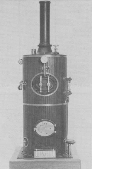
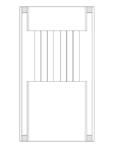
My experience is with loco or traction engine boilers where all surfaces of the pressure vessel that are exposed to the products of combustion must be protected by water to prevent burning of the steel. In a vertical boiler what protects the upper part of the firetubes and is there a formula or recomendation for tube lengths? Thanks John

The proposed boiler barrel is 10" schedule 40 pipe, and the firebox will be either 6" or 8" schedule 40 pipe. The firebox access tube is 3" schedule 80 pipe. The boiler would be 22" high with 17 - 3/4" tubes. it would measure about 14" between the tube sheets
 
Prospect said:
In a vertical boiler what protects the upper part of the firetubes and is there a formula or recomendation for tube lengths?
John,
While I've never seen this answered in respectable text my contention has always been that in the upper 1/3rd of the flues one would expect the flue gasses to have lost considerable heat, or at least enough heat so that the steam itself would absorb enough of the remaining heat to prevent overheating and in the process become to some degree superheated. There is a proven and long accepted formula for flue for ID to length ratio which I know works for horizontal fire tubes but I've never been sure it applied to vertical flues.
 
If at the top of your boiler you have a similar sized tube to the firebox that extends down about 3" with the tube plate at the bottom of this, the minimum water level can be set at say 2" from the top of the boiler and there is a steam space all around the top of the boiler but the vertical flues are at leas t1" below water level.

John Haining's Caradoc boiler is done like this.

J
 
Jason,
The type of boiler you just described is known as a submerged tube or submerged head boiler.

John, I am assuming you are talking about welded cleanout holes with threaded plugs. Hand holes with a dog is what we used on ships which is ASME code for the most part. That might be allowed and would look a lot less klunky. The manholes look similar only big enough to squeeze through.

Dan
 
Thanks Gentlemen for your replys.

GWR, Your info confirms much of what I've been told or read. They say that the saturated steam will cool the tubes and as you say superheat or maybe dry the steam. I would like to use copper tubes. Do you think in a vertical boiler considering the tube exposure would copper or steel tubes be better.

Jason, I have looked at that option. It appeals to me in that it would make attaching the smoke box neater. I'll do another layer in the drawing with that option. Nice thing about CAD.

Dan, The fittings I was concerned about were the blowdown/ cleanout fittings above the mudsill. By code they were required to be 1" and that required a 1.875" hole for weld in fittings. This other than looking bad made the centerline of the fitting to high above the top of the mudsill in my opinion. I changed the design to use three 1/2" fittings on the mark 3 model. I wanted a large cleanout in the back of the boiler where it doesn't show so much and went with the Australian code and used an eliptical opening 2.5 x 3.25" a few inches above the crown sheet.

The attachment gives some dimensions. The top tube sheet is 3/4" thick and sits on top of the barrel. I wanted to be able to tap directly into it as I'm not quite sure of the port positions. Is that likely to be a problem? I'm a welder but not B-Pressure and would not be welding this proposed boiler but I couldn't see any way to weld the tube sheet on due to it's thickness if it was down in the barrel.

Thanks, John


Donkey Boiler.JPG
 
Lots of tubes there John...Have you looked at ligiment distance?....might be a bit tight.

I'm told that small boiler shouldn't use real small tubes as they carbon up readily.

Just an observation....

Dave

 
Dave, I did check the distance between the tubes when I had drawn an 8" diameter firebx but not when I changed it to 6" diameter. I will check that now. John

Checked it and the distance between the tubes and from the tubes to the firebox inner wall is 3/8" The tubes are 3/4" diameter.
 
Prospect said:
GWR, Your info confirms much of what I've been told or read. They say that the saturated steam will cool the tubes and as you say superheat or maybe dry the steam. I would like to use copper tubes. Do you think in a vertical boiler considering the tube exposure would copper or steel tubes be better.
John,
I would use rolled-in copper, but for no other reason than I know how many small steel boilers have used them with great success over the years. I used the term "superheat" to indicate an increase in steam temperature, however slight, above 212, but drying is a better description of what is actually happening.

The formula for horizontal fire tubes gives an ID for your flue length of around .465" which is close enough to 3/8" Type K or Type L copper. I didn't notice if you named the fuel you plan to use but if it's gas then the .402"/.430" ID of Types K/L would do just fine. In addition the flue-to-grate area ratio of model boilers, which I think yours must be considered, is approximately 1:10, IIRC, which means that sufficient draft and exhaust can be had with a total flue area of 1/10th the grate area. Someone please correct me if I've recalled that ratio incorrectly. Thus for your boiler, with a grate area of let's say 18sq/in, the number of 3/8" Type L copper flues would be 12-14. Whether these guidelines for horizontal boilers apply to verticals, at least so far as flues go, I don't know. I think a vertical can be easily over-flued to the point where much useful heat will go up the stack.
 
John,
I just happened to have a set of plans for a 6" copper vertical boiler handy. These plans were sold by Saturated Steam in the 80's. The boiler was designed by F. B. Gittins of Rugby England.

The distance between the tube sheets is 7.25" and the design water line is 3" below the top tube sheet. Here is a photo of the boiler and the hand/cleanout holes I mentioned can be seen just above the mud ring.
Untitled.jpg


Kozoverthmem.jpg

This is a sketch I made of a submerged tube vertical boiler.

Dan


Actually GWR...minor point but it is the degrees over the saturated steam temperature at the operating pressure. The temperature above 212 would be superheated steam at atmospheric pressure and of course below that pressure....but above that pressure it would be at best saturated steam, or a mixture of steam and water or just water.

A mollier diagram would show this quite clearly.

Dave
 
Dan that sketch is just like the boiler I mentioned

John if you want to see a reduced drawing PM me.

J
 
GWRdriver said:
The formula for horizontal fire tubes gives an ID for your flue length of around .465" which is close enough to 3/8" Type K or Type L copper. I didn't notice if you named the fuel you plan to use but if it's gas then the .402"/.430" ID of Types K/L would do just fine. In addition the flue-to-grate area ratio of model boilers, which I think yours must be considered, is approximately 1:10, IIRC, which means that sufficient draft and exhaust can be had with a total flue area of 1/10th the grate area. Someone please correct me if I've recalled that ratio incorrectly. Thus for your boiler, with a grate area of let's say 18sq/in, the number of 3/8" Type L copper flues would be 12-14. Whether these guidelines for horizontal boilers apply to verticals, at least so far as flues go, I don't know. I think a vertical can be easily over-flued to the point where much useful heat will go up the stack.

GWR, This boiler would be gas fired (propane ). I had wondered if with 3/4" tubes if I wasn't creating a torch to cook my smokebox and was wondering about an arch of some kind. Did a quick redraw with 14 - 1/2" od tubes and a submerged flue design as Dan and Jason have suggested. It looks interesting as the upper submerged section would act as a stay for the upper tube sheet if necessary. John

Donkey ( Submerged Tube ).JPG
 
steamer said:
Actually GWR...minor point but it is the degrees over the saturated steam temperature at the operating pressure.Dave
Dave,
Yes I realize that, but for the moment I decided for simplicity's sake not to go into it, just as I've decided not to point out that because the flue length has changed so has the length-to-diameter ratio, if we accept that the usual fire tube formula applies to vertical tubes, which I'm not sure of. So many slippery slopes . . . ::)
 
GWR No worries mate!

It's steam....it's self integrating anyway......

;D


Did some calculations today. On a submerged tube Boiler with copper tubes some dimensions I would like to go with are as follows.

1. 2" steam space above high water level.

2. A 6" o.d. Extention (smokebox ?) extending from the bottom of the upper tube sheet to the top of the boiler top sheet long enough to give a 3" operating water level measured from the bottom trycock to the top trycock. Aprox 5.75" long. Sorry if that sounds confusing. This would give an exposed to water tube length of 7.625" There would be 14 -3/8" tubes (actual .5"o.d. with .049" wall)

3. 10.75" o.d. boiler shell with a 6.625" o.d. firebox giving a water leg width of about 1 .625".

4. The hydro test volume (calculated) would be 4.24 Imp. gals (19.283 liters).
3.66 Imp. gals (17.31 liters) at operating level or middle trycock.

5. The total heating surface would be 491.64 Sq inches which includes that upper extention ( internal smokebox?) I'm not sure what you would call that piece.

6. The grate to flue ratio would about 10.25 to 1.
I can see I'm wrong on this ratio. I used the tube o.d. rather than i.d. Correct ratio would be closer to 15.9 to 1. This doesn't allow for any restriction in grate area due to burner jets.

Any advice would be appreciated. John
 
Hi, further to this boiler, I've been working on a spreadsheet where I can change dimensions and not make me wish I paid more attention in math class. While a work in progress it's functional.

GWR, I have searched the internet and my own book collection which is huge and I can't find any definite info on grate to flue area on model vertical boilers. On full scale boilers it appears to be about 5 to1. Just looking at the model drawing 5 to 1 appears to be excessive due to the short flue length, so I am going to go with 10 to 1 until I find other info.

In the short term could someone let me know if the mudring enters into the heating surface calculations or if it is considered a none heating surface. It would appear to me that the mudring would actually draw heat away from the water heating surface but is it included in the heating surface calcs.

Thanks for any replys, John
 
Thanks Jason, Interesting thread. I'll run the tube calculations shown in the thread later. I finally found my copy of the Model Engineers Handbook and I think there is some info on tube calculations there too. John
 
OK, doing the steam consumption calcs on this donkey engine set with the engine set at its maximum load (100psi), would you design the boiler steam generation (heating surface) for that demand? I think that full load would only occur for a fraction of the running time. My concern is that to achieve that constant output might require a fairly large increase in heating surface (more tubes) when I would like to keep things fairly simple? John
 
John,
I saw on the other thread you are working the problem with 120 rpm. Well I will say it has been a number of years since I have seen steam winches in regular service but that seams a bit high and as you say that is not continuous running.

With logging the cable is only under load while lifting just like the old ship rigging I saw as a cadet. The duty cycle has to be less than 50%.

Did you work the calculations for the original design for heating surface? If you worked that backwards you might get close to the model design RPM for your heating surface check.

Dan
 

Latest posts

Back
Top