Back in June I found myself in Stuttgart with a day to spare, so I visited the Porsche and Mercedes-Benz Museums. I highly recommend both places- but I'm pretty sure the sort of people who frequent HMEM would need no encouragement to visit these cathedrals of automotive engineering. When you enter the Mercedes-Benz Museum a space age-elevator whisks you to the top floor where the oldest machines are. You then proceed down the building in a spiral fashion, progressing through the 130 years or so of company history.
http://www.mercedes-benz-classic.com/
http://www.porsche.com/international/aboutporsche/porschemuseum/
Back in 1885 Daimler and Maybach worked for the Deutz Gas Engine Company. They wanted to develop small, portable engines for burgeoning mobile applications (boats, horseless cariages, airships - that sort of thing) and Deutz wanted to stick to the large, heavy and slow stationary gas engines- so Daimler and Maybach left Deutz to start their own business. Working out of a greenhouse converted to a workshop they developed their first product- the Standuhr (grandfather clock) engine.
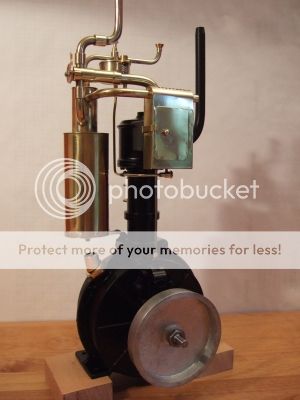
The Standuhr is a single cylinder, 4 stroke engine. The exhaust valve mechanism is relatively normal, but the intake is a loose spring, suck to open design. Ignition is via hot tube (electrical ignition was not deemed reliable enough in those days). The product was a success, the high speed of the engine (600 rpm!) let them pack more power into a relatively small and light package. They created a two wheel test platform for it (the first motorbike) and they installed the engines in boats and early cars. They went on to to create variants of the design including a V-twin. In many ways the Standuhr is an ancestor of the all modern car engines, and as such would probably make it onto a list of the top 10 historically significant engines.
I became interested in the motor and its history. The fact that it was built in a greenhouse/home-workshop (admittedly by engineering geniuses, which I am not) made it fairly approachable as a project. I took a look around to see if anybody else had taken it on and found that Heinz Kornmueller of Classic Motors (http://www.classic-motors.at/modellmotoren/modellmotoren.htm) had built a replica and was offering a casting kit.
I like to make patterns and cast-metal, so I'd rather get a plan and do my own thing than buy a casting kit, but the classic motors plans are not fully dimensioned, they assume you have the casting kit. So I bought a casting kit. Since the design is metric and I live in an English unit country it gave me an excuse to scale the design to make it more inch compliant. That is: Using the original castings as a model- produce scaled up patterns using the divide by 16 approach (E.g. 7mm becomes 7/16 inch. This effectively scales everything by 25.4/16 or about 1.6). You end up with something about the size of a lawn mower engine. The bore is still relatively small - 1.25 inches.
And so the work begins.....
There are five castings to make.
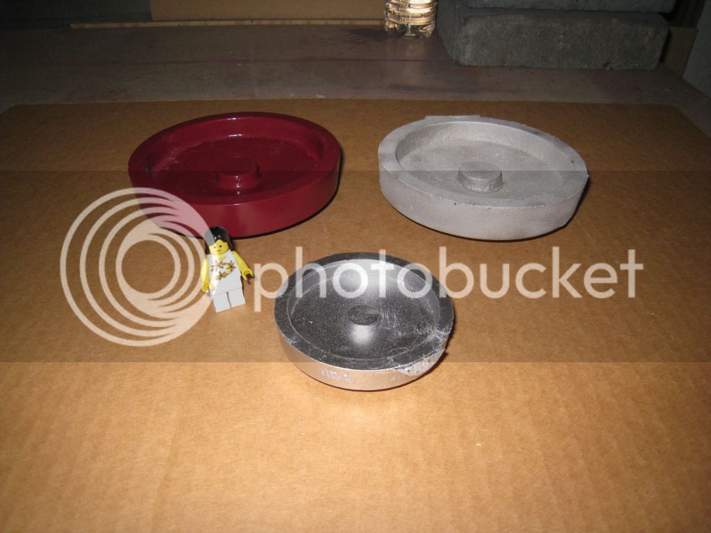
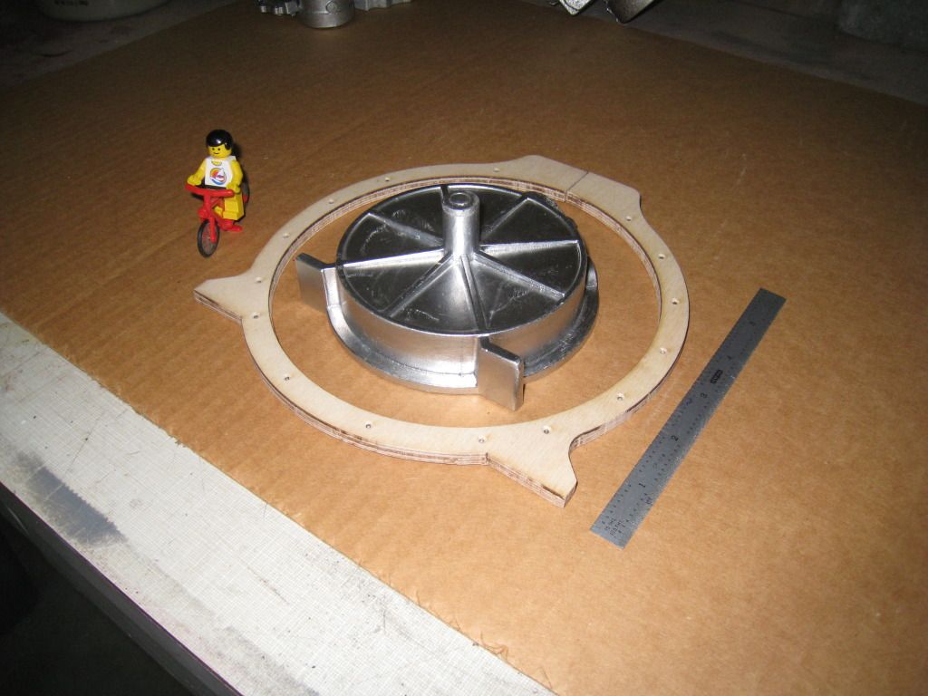
There's an external drive wheel on the cranks. It's not really a fly wheel because the internal crank has far more mass. It's used to start the motor. I guess you could run a pulley off it. Here you can see my pattern, my casting and the original casting.
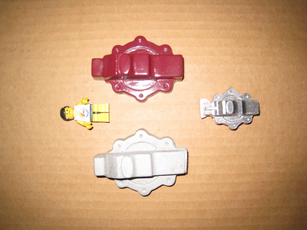
This is the cover for the exhaust valve pushrod that is coupled internally to the crank. It's more elaborate then it needs to be on a purely functional basis- there are some nice 1880's style decorative elements.
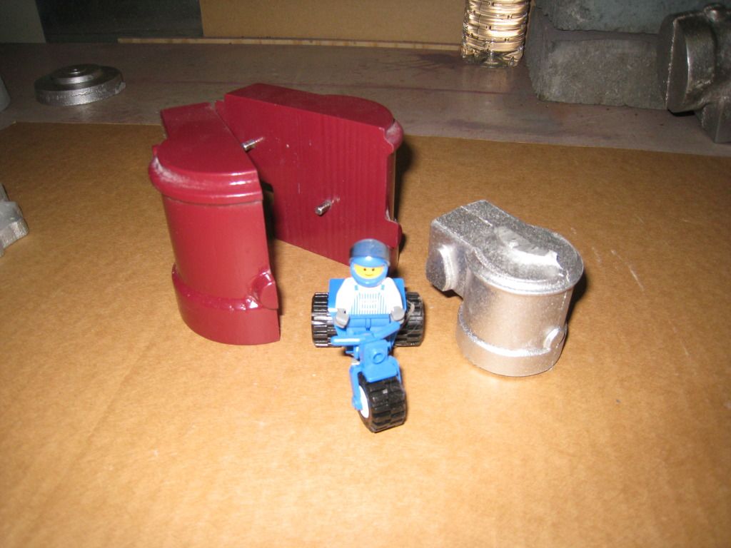
Here's my cylinder head pattern and the original casting.
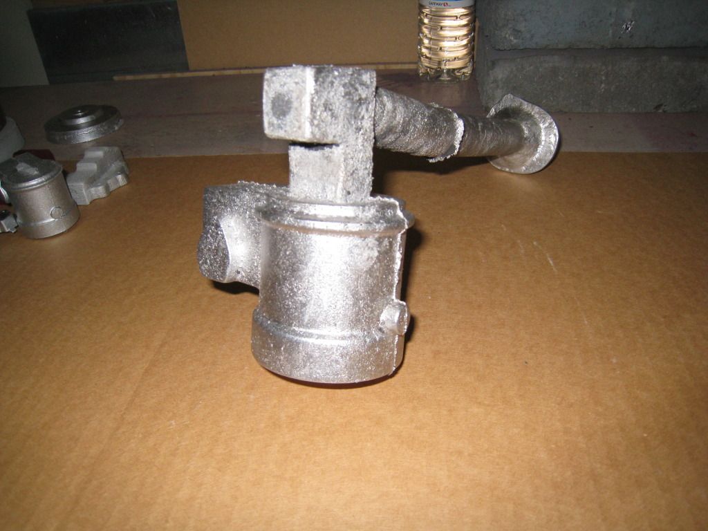
And here's the first screw up of the project. Given the bulk of this casting I suspected I would have shrinkage problems, but I decided to try a simple riser and see if I could get away with it. I couldn't. One side of the casting is ok, but the other side has shrinkage that it unacceptable. I need to put a bigger riser on it that will hopefully feed the casting while it solidifies. The great thing about casting is that you can melt your mistakes. I'll probably redo the other castings and make a couple of copies of everything to allow for machining screwups.
The crankcase halves are the most complicated patterns and are still a work in progress.
Internally the crank, conrod and camplate are made from plate steel. The camplate is interesting. The exhaust valve is driven from a cam follower that rides around in this loop-the-loop style slot in a cam plate. This allows the engine to avoid the need for 2:1 timing gears. I suspect they were solving the same problem that Atkinson solved with his engine- Deutz had a patent on the use of 2:1 timing gears.
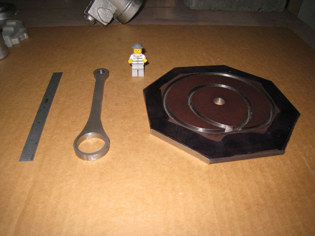
The curves in the camplate have forced me to expand my machining horizons. I used a CAD/CAM and a Tormach CNC mill to carve them out. Now that I've done some analysis on the curves I think I'll redo that part with slighly different curves to create a performance cam with a shorter exhaust valve opening. I like CNC - the conrod was carved out of 1/4 inch cold rolled plate and came out quite nicely.
And on it goes.....
http://www.mercedes-benz-classic.com/
http://www.porsche.com/international/aboutporsche/porschemuseum/
Back in 1885 Daimler and Maybach worked for the Deutz Gas Engine Company. They wanted to develop small, portable engines for burgeoning mobile applications (boats, horseless cariages, airships - that sort of thing) and Deutz wanted to stick to the large, heavy and slow stationary gas engines- so Daimler and Maybach left Deutz to start their own business. Working out of a greenhouse converted to a workshop they developed their first product- the Standuhr (grandfather clock) engine.
The Standuhr is a single cylinder, 4 stroke engine. The exhaust valve mechanism is relatively normal, but the intake is a loose spring, suck to open design. Ignition is via hot tube (electrical ignition was not deemed reliable enough in those days). The product was a success, the high speed of the engine (600 rpm!) let them pack more power into a relatively small and light package. They created a two wheel test platform for it (the first motorbike) and they installed the engines in boats and early cars. They went on to to create variants of the design including a V-twin. In many ways the Standuhr is an ancestor of the all modern car engines, and as such would probably make it onto a list of the top 10 historically significant engines.
I became interested in the motor and its history. The fact that it was built in a greenhouse/home-workshop (admittedly by engineering geniuses, which I am not) made it fairly approachable as a project. I took a look around to see if anybody else had taken it on and found that Heinz Kornmueller of Classic Motors (http://www.classic-motors.at/modellmotoren/modellmotoren.htm) had built a replica and was offering a casting kit.
I like to make patterns and cast-metal, so I'd rather get a plan and do my own thing than buy a casting kit, but the classic motors plans are not fully dimensioned, they assume you have the casting kit. So I bought a casting kit. Since the design is metric and I live in an English unit country it gave me an excuse to scale the design to make it more inch compliant. That is: Using the original castings as a model- produce scaled up patterns using the divide by 16 approach (E.g. 7mm becomes 7/16 inch. This effectively scales everything by 25.4/16 or about 1.6). You end up with something about the size of a lawn mower engine. The bore is still relatively small - 1.25 inches.
And so the work begins.....
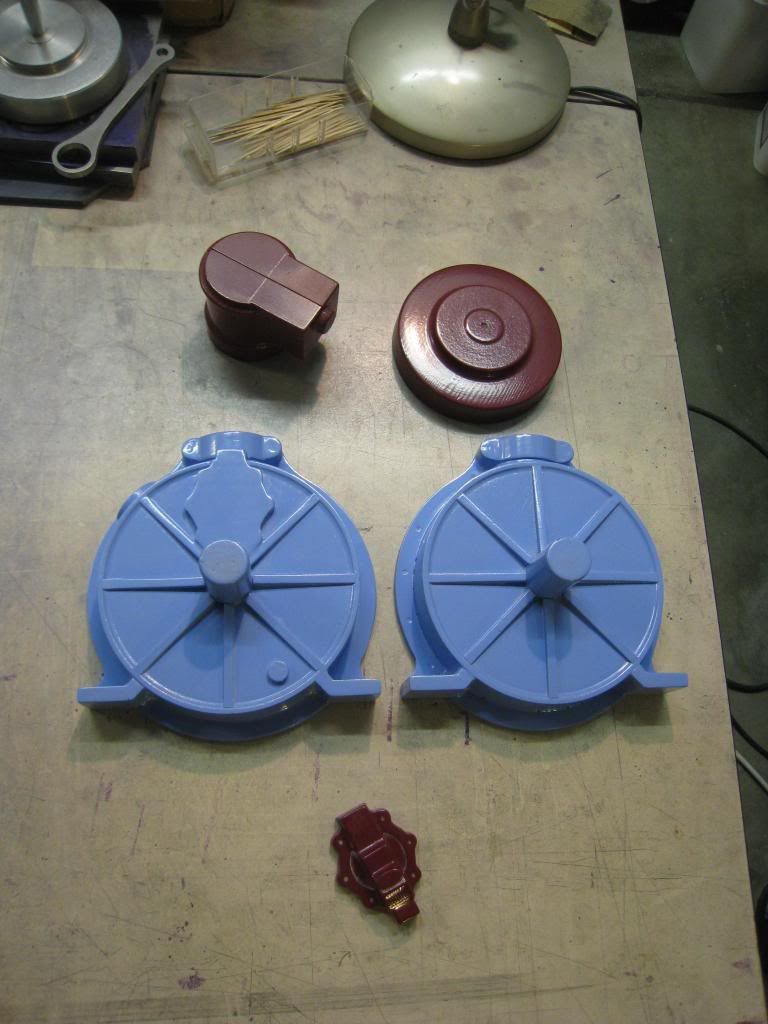
There are five castings to make.
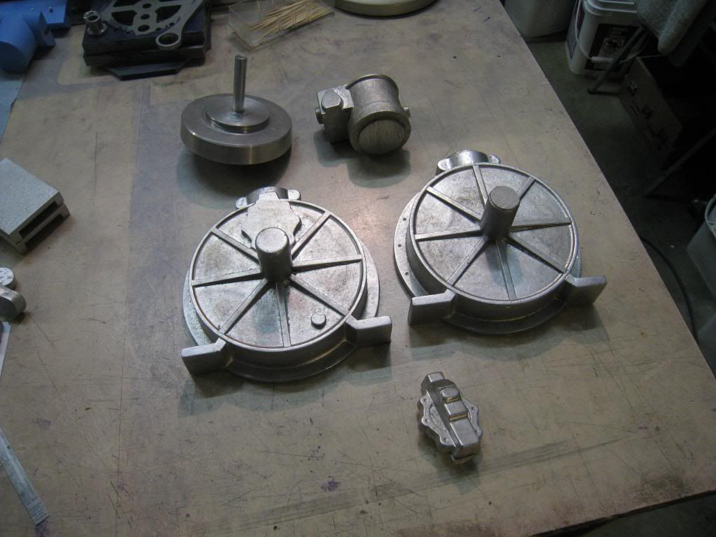
There's an external drive wheel on the cranks. It's not really a fly wheel because the internal crank has far more mass. It's used to start the motor. I guess you could run a pulley off it. Here you can see my pattern, my casting and the original casting.
This is the cover for the exhaust valve pushrod that is coupled internally to the crank. It's more elaborate then it needs to be on a purely functional basis- there are some nice 1880's style decorative elements.
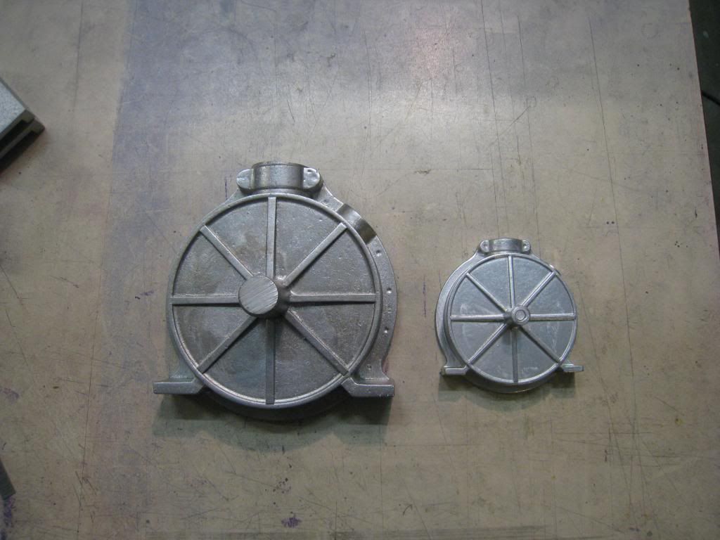
Here's my cylinder head pattern and the original casting.
And here's the first screw up of the project. Given the bulk of this casting I suspected I would have shrinkage problems, but I decided to try a simple riser and see if I could get away with it. I couldn't. One side of the casting is ok, but the other side has shrinkage that it unacceptable. I need to put a bigger riser on it that will hopefully feed the casting while it solidifies. The great thing about casting is that you can melt your mistakes. I'll probably redo the other castings and make a couple of copies of everything to allow for machining screwups.
The crankcase halves are the most complicated patterns and are still a work in progress.
Internally the crank, conrod and camplate are made from plate steel. The camplate is interesting. The exhaust valve is driven from a cam follower that rides around in this loop-the-loop style slot in a cam plate. This allows the engine to avoid the need for 2:1 timing gears. I suspect they were solving the same problem that Atkinson solved with his engine- Deutz had a patent on the use of 2:1 timing gears.
The curves in the camplate have forced me to expand my machining horizons. I used a CAD/CAM and a Tormach CNC mill to carve them out. Now that I've done some analysis on the curves I think I'll redo that part with slighly different curves to create a performance cam with a shorter exhaust valve opening. I like CNC - the conrod was carved out of 1/4 inch cold rolled plate and came out quite nicely.
And on it goes.....
Last edited:
")