Casting Kits I would like to see For Sale Again

Home Model Engine Machinist Forum

Help Support Home Model Engine Machinist Forum:

This site may earn a commission from merchant affiliate links, including eBay, Amazon, and others.
Although it would be nice to make them like the originals there are some compromises that have to be made as the size comes down for example it may not be possible to pour babbitt through a gap that is 1/3rd or 1/4 of the original without it cooling & setting solid before it flows right through. You may have to opt to cast a solid cylinder and then machine that as you would a piece of bronze.

Slender parts were often done in ductile iron not grey on full size and it becomes even more important as the cross section comes down to use ductile so your castings don't break, quite a few kits that I have made use ductile iron for some or all of the parts, others opt for various bronzes and gun metal which will just bend, this also helps eliminate the problem of chill if the thin iron cools too quickly.

Also I'm not averse to some parts being cast in aluminium, having done a couple of the Root & Van Der Voort engines by Rocky's they are so much easier to pick up and handle. Lets face it once painted who knows what the metal is. This would also mean more people could home cast as there are no where near as many that can melt iron as there are non ferrous.

As mentioned above I quite like a bore around the 1" mark and have done about 12 engines now with a 24mm bore, some scaled down from larger old model designs which works out well. It opens up the number of people that can make the model as flywheels tend to fall into what can be one on teh generic 7x ?? MiniLathe, material costs are not too high, you get get a lot of them on a shelf and easily handled.

Those two last points would also suit the 3D files option more than patterns as self printed or cut patterns could have the correct shrinkage allowance added for whatever material they were being cast in and if someone wanted a smaller version could simply reduce the file size
 
I had asked about some patterns on eBay a few months ago as I have the same general feeling of hating to see the old patterns go away forever. The general opinion seemed to be many of the old patterns are outdated or need modifications to be used today. I don't even know enough to be dangerous about commercial casting but am intrigued by this idea of a pattern library sort of thing. Do the small foundries have standard requirements for patterns, backers or what ever else you need? I'm sure they would be more receptive to someone walking in with their patterns ready to go instead of having to hold the hand of people like me over and over again. I don't know what I can do but I think this is an idea worth pursuing. Bob
 
Cretors engines had poured babbitt bearings, and they are quite small, so it is possible.
I guess they preheat the bearing shell, but that is typical for pouring babbitt bearings.
The bearing shells should also be pre-tinned.

Ductile iron is an excellent idea for small engine parts.
I have not been able to find any significant amount of nickle-mag, and the sulphur has to be reduced with calcium carbide, or so I am told.
I have calcium carbide. Perhaps one day I will find a significant amount of nickle-mag.

Generally, I think the guys who have been in the casting kit business set up match plates, with one or more patterns mounted on them, and all of the runners and gates also on the plate.

Maury use to make hard plastic replicas of his permanent patterns, so that the original did not have to be sent to the foundry.

Aluminum is not a bad trade off, especially if you give it the two-stage heat treatment process to reach an approximate T6 hardness.
Flywheels really need to be cast in a more dense metal than aluminum.

Bronze is also a pretty good tradeoff if you can control the zinc burnoff.
I have the ingredients for some lead-free bronze.
Note that if you are hitting bronze temperatures in your furnace, you are very close to gray iron temperatures too, so it is a pretty easy step to just use gray iron.
Gray iron usually needs a trace of 75% ferrosilicon added to it to improve machinability, especially in thin castings.

.
 
Last edited:
@GreenTwin, we agree that the available casting kits on the market have been dwindling; however, rest assured that Joy and I have no intention of slowing up in doing our part toward adding to the market, and continuing to support the Hobby with our little business. We purchased a long-extinct project back in February after getting a lead at the Cabin Fever Expo. Given that part of the deal is that we produce several finished engines for the family, we have put another, original, project on hold while I completely redo the drawings and patterns. The "new" project is a 1/4-scale, 1/2 Hp New Holland engine that hasn't been on the market for ~20 years.

The time delay is important to us when considering purchasing projects from other suppliers (and @Oldiron why we didn't consider the Woodpecker engine on eBay). What we've found is that there is an initial rush of sales for a "new" project on the market, then after a year or two, sales dwindle to a trickle. This also may explain why some suppliers quit after one or two kits. This does explain why we try (key word, try) to have something new each year. Once I retire in a few years, I plan to work full time on the hobby-business.

To give a better idea into what's involved in bringing an older kit back to market..... After nearly two months of evenings, I've finally finished the 3D modelling of the NH engine base casting. This model will be used to generate the matchplate pattern and 4 core boxes needed to cast. Since the patterns were lost, I scanned an unfinished casting, and then used it as a guide to model the casting in CAD. I've attached photos and screen shots of a finished engine, scan and model overlay, finished model, and original drawing issued with the kit. Now to "machine" the virtual casting and produce the first detailed drawing. Enjoy!

Regarding using older matchplates with commercial foundries, each foundry has unique requirements due to the equipment they have available as well as their foundryman's preferences on gating, risering, matchplate size/style, etc.. Fewer and fewer foundries use manual moulding equipment such as jolt-squeezers. Most have gone to automated machines. Most won't even consider a job for fewer than what they would consider a production run. Further, most model engineer-produced matchplates do not cast in multiples, having 1 of each part on each plate rather than multiples of each part on one plate for each part. The NH engne I'm working on will require 10-each, 12x18 matchplates.

We plan to cast the engine in C873 Everdur, Silicon Bronze. We can cast either on our own or with the foundry we work with in Hanover. Given that my initial run will be for 30-50 sets, I will be contracting this out.

Regarding aluminum castings and heat-treatment, we use 713 Tenzaloy aluminum which self-hardens to ~T6 in about 2 weeks - sidestepping the heat treating altogether.

Todd.
 

Attachments

  • NH Base Pattern Final Render 3-4 Overlay.png
    NH Base Pattern Final Render 3-4 Overlay.png
    463.4 KB · Views: 3
  • NH Base Pattern Final Render 3-4 view.png
    NH Base Pattern Final Render 3-4 view.png
    988.2 KB · Views: 3
  • nh-004.JPG
    nh-004.JPG
    386.6 KB · Views: 2
  • Fiore NH Model 3_clipped_rev_1.png
    Fiore NH Model 3_clipped_rev_1.png
    2.4 MB · Views: 3
Last edited:
Todd-

I feel for you guys in the casting kit business, but I am really glad to see someone still offering kits.

I believe everything you say, ie: there is an initial rush on orders, and then things taper off.
A large casting run could leave you stuck with a large number of castings, which could be a lot of money tied up for who knows how long.

There is definitely a finite number of engine builders in the world, and unfortunately I see that pool shrinking, at least in the US.

On the plus side, there are some awesome tools available these days to help, such as 3D modeling, 3D printing, and as you illustrate, 3D scanning.
With today's modern tools/software/hardware, model engines can be made more accurately than ever before.
It should be noted that the Stuart molds were what I consider very advanced for their time, and are still very advanced today in my opinion.

With bound sand, the castings can be made to near net, ie: their as-cast dimensions are very close to the final machined dimensions.
With 3D printed patterns, and bound sand, the accuracy of the cast part can be excellent, and infinitely more accurate than hand made patterns used with greensand.

I can see where the matchplate use could be a drawback, with no two foundries using the same equipment.

The modern foundries I see often use a lot of bound sand.
Resin bound sand is fast, highly accurate, and does not require the pressing/pounding to compress the sand.
If you pound on resin-bound sand, you basically just cause it to shift sideways and create voids around the pattern.
Resin-bound sand should be pressed into place by hand, with a firm pressing action, but NO pounding.
Resin-bound sand gives a superb finish to the iron casting surface, especially when a ceramic mold coat is sprayed onto the mold interior.
Resin-bound molds would be a good choice for limited runs of castings.

I also see 3D printed sand molds starting to be used more and more in foundry work, which is often good for prototyping and low quantity runs.
Time is often critical in industry, such as when a huge machine suffers a part failure, and a replacement is needed within days.

The 713 aluminum sounds like a fantastic alloy.
That is the first I have heard of that material.

It should be noted that 3D models can be developed from photos only.
Once you get the hang of 3D modeling, the various shapes used for engines can be recreated relatively easily, and it is much easier to manipulate the various parts of a model using the built-up 3D model, as opposed to scanning.

Don't forget to scale up the scan a bit to allow for shrinkage.


Below is a 3D model for a Speedy Twin I have been working on.
I am no model engine expert, but rather a self-taught hobby guy, but this model illustrates the possibilities for even someone with little modeling experience.

This engine would lend itself to some sort of lost-wax or lost-PLA process, but it could be cast at scale.
I studied the Speedy Twin frame, and basically created the 3D model by building up one surface at a time, just as the did when making the original patterns.
One has to think as if one were making the original full sized pattern.
This engine has a large number of passages above the two cylinders.

The Speedy Twin is not for your average model engine kit builder, but this does illustrate what the possibilities are in this hobby.

.

3D-PRINT-01.jpg
rImg_3164.jpg
rImg_3166.jpg
Image12.jpg
Image111.jpg
 
Last edited:
  • Like
Reactions: Zeb
Thanks for the insight Todd. having in the past done some initial drawing of a new Holland based on the Briesch drawings with a view to fabrication I know it is not an easy shape to draw and you have done a very good job. It is engines like these with their more organic and flowing lines that need a lot of design work and CAD skills compared with something like Pats example which is mostly fairly basic geometric shapes joined together with just a few more complex areas around the crank enclosure. ( not putting yours down Pat just using it as an example)

Now that you have it in 3D producing the patterns with modern methods will be easier than trying to make a wood pattern though I do wonder how the casting you used compares to an original, I'm sure there would have be some artistic licence, sanding and blending with bondo by eye.

30 -40 sets in the initial run is quite an investment in capital plus your initial time and purchase costs though I suppose you can get better rates from the foundry if they are doing a batch particularly if all gated and on matchplates as the labour cost will be lower than raming up individual patterns
 
I have seen at least one individual (the Merlin casting guy comes to mind) that took pre-orders.

Pre-orders could potentially avoid over or under production.

I am not sure if many would pay a percentage up front though, after what happened with one casting kit company (whose name I will not mention) who took orders and money, and then apparently closed down, with no refunds on some very expensive casting kits.

Jason is correct, Todd's engine frame is a rather tricky affair, with lots of curves.
It makes you wonder how they made the original patterns.
The pattern makers of old where some very good woodworkers to be sure.

.
 
Lots of good insight and conversation here. THANK YOU!!

The NH base casting is the most-difficult rendering I've done in the 35+ years working with CADD and 20+ years of 3D modeling engine designs. Jason is spot-on. This thing is a beast and has pushed me and my CAD system (TurboCAD Pro-Platinum) nearly to the breaking point. I use lofting to produce shapes with draft. Similarly, I've been using complex surfaces to cut with. These can make for some difficult filleting as the modeling engine (ACIS) just doesn't know what to do with some of the shapes generated. Even the order in which the blended edges are selected can result in working, not working, or sometimes crashing the entire program.

Scanning helped tremendously and saved a huge amount of measuring. The attached screen shots show the scanned (orange) original against the 3D modeled copy. I've also refined the design, adding a bead around the top of the hopper, proper flanges, etc.. The fourth attachment is the 3D printed draft next to the originals.

All this said, and back to the original topic, it takes a lot of work to bring a 20-50 year old project up to today's standards and back to market. Rough castings and sometimes sketchy drawings to go with them were the norm at one time, but are no longer acceptable. Not to say that there weren't some beautiful kits out there too. I miss them as well.

BTW, I get as much enjoyment out of challenging myself with the 3D models as with machining the prototypes and this one has been a ton of fun. Sharing this with others is why we do what we do.

@GreenTwin , That's a really nice looking engine and nice looking work along with it. Cool!

@GreenTwin , I'm also amazed at the skill of the old patternmakers. Truly an art!

Todd.
 

Attachments

  • NH Base Pattern Final Render 3-4 Overlay.png
    NH Base Pattern Final Render 3-4 Overlay.png
    463.4 KB · Views: 5
  • NH Base Pattern Final Render Bottom Overlay.png
    NH Base Pattern Final Render Bottom Overlay.png
    346.5 KB · Views: 2
  • NH Base Pattern Final Render Top Overlay.png
    NH Base Pattern Final Render Top Overlay.png
    441.7 KB · Views: 3
  • IMG_20230423_131634033.jpg
    IMG_20230423_131634033.jpg
    775.9 KB · Views: 4
@littlelocos Awesome modeling there. Looks tight against the reference mesh. 3D scans can be a little wonky too based on the quality of the scan. 👍
I spent some time this winter brushing up on surfacing and these would be fun projects to dive into. Anyone have copyright-safe scans/open drawings to point to? I might start looking around (free or paid).

*Edit: Here's a 30 minute doodle of the bottle engine base. I can push/pull to where the curves need to go.Doodle.png
 

Attachments

  • BottleEngine_Base.zip
    507.2 KB · Views: 2
Last edited:
Todd-

It is very exciting to see someone bringing back an old design.

I also understand how tricky that can be, and also how time consuming that can be.
Using 3D for engine work has definitely forced me to improve my 3D modeling skills significantly.

Great photo of your efforts !

I think your engine will be very popular.

Pat J

.
 
I suppose another advantage of 3D modelling and 3D printing the patterns is that it would not be hard to offer the model in larger scales, I see this with figure model where they are sculpted in one scale and then sold in several options.

Zeb, thanks for that had been thinking of doing a bottle engine though will have to scale it down as at nearly 900mm tall it's a bit big for my machines 😉 
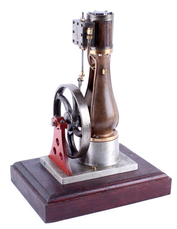
I'd probably CNC it with a split line vertically down the middle so I can get to it from inside and out. Though a little more bulbus at the bottom would be nice, something like this now out of production kit.

18-201222910549_original.jpg
 

Attachments

  • jb1.JPG
    jb1.JPG
    139.8 KB · Views: 3
  • jb2.JPG
    jb2.JPG
    53.6 KB · Views: 2
I suppose another advantage of 3D modelling and 3D printing the patterns is that it would not be hard to offer the model in larger scales, I see this with figure model where they are sculpted in one scale and then sold in several options.

3D modeling does help if you want to scale the model up or down.

The 2D drawings have to be reworked though, since fasteners and drill sizes will no longer be standard when you start scaling things.

Changing fastener, shaft and drill sizes is not too bad, compared with starting from scratch.

I have seen the Galloway engine anywhere from 1/3 all the way down to a very tiny unit.
I have a photo of a Galloway lineup of engines running at an engine show, with one engine at every scale.
I think it was at Algonquin.

.
 
My frame design is from an old book by Scranton.

Apparently this was a full sized bottle engine design.

A bit trick to model.
I had trouble with the beading at the top.

Figuring out the molding is also a bit tricky.
A few retracts will be required I think.

Its obvious from the Scranton drawings that the cylinder bolted on from the inside of the frame.

.

Bottle-Engine-Scranton-01.jpg


Bottle-Frame-rev-13-06.jpg


Bottle-Frame-rev-13-08.jpg


Bottle-Frame-rev-11-04-13.jpg
 
Last edited:
Thanks, I really like the bottle frame design; it has such a unique look to it, sort of like a ball hopper Monitor.

Some of the cylinders bolt from the bottom, and some bolt from the top.

I am not sure my Scranton design actually bolts from the bottom, but I think I can make it work that way.

I saw a video of a twin bottle engine, and that was very cool, but probably not too practical due to the width of the bottom of the frame.

.
 
Here is the twin I saw.

At first I thought it was something cobbled together from two single engines, but the base is cast as one piece, which makes me think it came from the factory as a twin design.

It runs like a champ, and so I guess it is a practical design, or so it would seem.

 
  • Like
Reactions: Zeb

Latest posts

Back
Top