
You are using an out of date browser. It may not display this or other websites correctly.
You should upgrade or use an alternative browser.
You should upgrade or use an alternative browser.
Carburetor information
- Thread starter gbritnell
- Start date


Help Support Home Model Engine Machinist Forum:
This site may earn a commission from merchant affiliate
links, including eBay, Amazon, and others.
- Joined
- Jul 16, 2007
- Messages
- 2,985
- Reaction score
- 1,050
Quite a few years ago I had attended the NAMES show in Wyandotte, Michigan. There was a fellow there by the name of Lee Root. He always accompanied Robert Washburn, the editor of SIC.
The one year he had his 4 cylinder DOHC engine running and it had a small throttle body fuel injection system. It worked great and you could look inside the throttle bore of the carb and see it spraying gas while it was running.
Sadly Mr. Root wasn't one to write down or share his information and this marvelous piece of engineering is only available for display.
It is currently on loan to the Sherline Craftsmanship Museum through the courtesy of Mr. Paul Knapp and can be seen here:
http://www.craftsmanshipmuseum.com/images/k104-RootDOHC2.jpg
George Britnell
Lakc
Well-Known Member
gbritnell said:It is currently on loan to the Sherline Craftsmanship Museum through the courtesy of Mr. Paul Knapp and can be seen here:
http://www.craftsmanshipmuseum.com/images/k104-RootDOHC2.jpg
I hate that site, they keep updating it and I loose an hour+ every time I go there.

If you spend any time on Kinsler or Hillborn mechanical fuel injection systems, you find they are a simple positive displacement pump with a whole bunch of calibrated leaks. I like to think even I can make things that leak, but the last pump I tried wouldnt even turn. :'( I will get there someday.... At the end of all these leaks, you flow the fuel past a barrel valve to individual injectors, which are very simple venturi's.
Here is a pic I took from way back in my racing mechanic days. The pump is a rotary vane type and belt driven right off the crankshaft at approximately bottom center. The topmost tank is the fuel tank (alcohol), the smaller tank is the radiator. You can see the huge (-6?) line feeding the pump is running directly underneath, and is the lowest fitting. The T right above that goes off to a brass body that contains a combination jet/pressure relief setup (calibrated leak #1) and dumps into the other T back into the tank. The other end of the T goes through the fuel filter next to the distributor and into the manual fuel shutoff valve which has its own return to the tank. The outlet of the shutoff valve goes to the barrel valve which is partially obscured by the #3 cylinder injector stack. The barrel valve is a variable leak with the return heading back to the tank on the rightmost fitting in the picture. What doesnt leak by the barrel valve flows to the 8 black hoses to the brass injectors underneath each throttle plate. The fitting at the very back of the pump runs to the "can" just forward of the fuel filter. That is a jet selector that allows you to choose leak #3 in 5 different sizes if I recall. It exits and enters the tank in the engine side of the T. Sorry if that all sounds about as simple as the tax code, but there it is.

Thanks for the link, George - I missed that one on my last look at the site.
Thanks too, Lakc - I like the concept. I'll have to ponder this some more. Plenty of leaks around here now the rainy season has set in, but they're all too large for a 1/4 scale V8. None of them taste of alcohol either...
Thanks too, Lakc - I like the concept. I'll have to ponder this some more. Plenty of leaks around here now the rainy season has set in, but they're all too large for a 1/4 scale V8. None of them taste of alcohol either...
Joachim Steinke
Active Member
- Joined
- Jun 14, 2010
- Messages
- 29
- Reaction score
- 22
Hallo everyone,
as fabulous George has started this very informative article about carburators some weeks ago I like to show you the new carb version I have designed a month ago for my latest 0.25 cubic inch 4-cycle gasoline driven engine.
My first version was a simple carb like the radio control people use on there methanol engines. I was inpatient and wanted to get the engine running, so I wasnt in the mood for long experiments and complex extra craftsmanship on this marginal component, but this was far wrong .ha ha ha .
The main dimensions are 6mm (0.24in) of free air passage and a reduced venturi area of 4.8mm bore (0.19in) in the rotating barrel type throttle.
I didnt last long to notice, that this arrangement was not the first choice for my need. Okay, the engine started from time to time, but it doesnt want to run longer than 20 seconds or so and it showed a lousy idle behaviour. Additional the gasoline level had a prominent influence on the whole function, being to low starting was nearly impossible, hanging the reservoir too high means the permanent danger of over floating the intake area.
Okay, to get at least any results with the existing material I tried to modify the venturi area. I made the fuel jet cylinder larger in diameter (from 2.4 up to 3mm) and let it now reach completely into the other side of the throttle barrel which means a quite heavy reduction of free section.
As George already mentioned, we tend to oversize the intake dimensions of our little gasoline motors, especially when we refer to comparable methanol engines. So, with this reduced width my engine was running a lot better. Suddenly I was able to speed up over 7000 rpm, could make long runs of 10 minutes ore more and the idle control was bearable too.
What left was a quite lousy starting behaviour, sometimes immediately running and then on other times it could drive me crazy, and the old problems with the influence of gasoline level.
My idea was that especially for the starting procedure the fuel jet needs the right fuel pressure. As the intake volume has only a small amount the vacuum from the venturi is too weak for the right starting mixture. It seems, that venturi proportions which are suitable for full throttle run dont work good for starting the engine at nearly idle setting. There is simply too little sucking on the fuel passages.
Okay, about three months after finishing the main engine I designed a complete new carburator .ha ha ha .
The new one is a mixture of a simple motorcycle type and a two needle methanol motor carb. It has a sliding barrel type throttle which contains the linear travelling idle needle and it got a float chamber too.
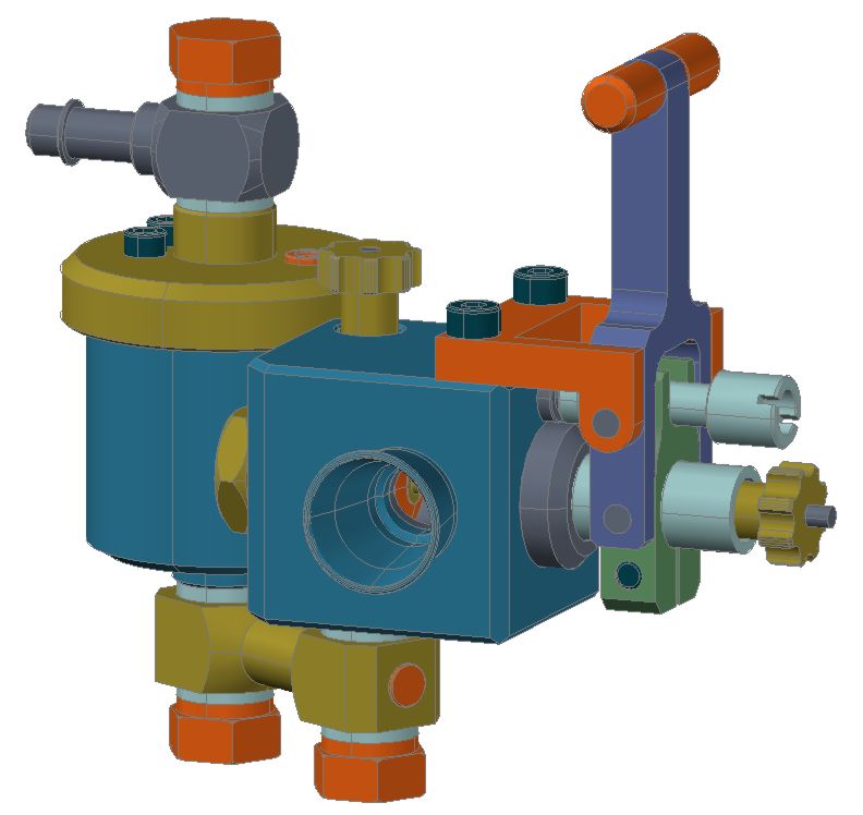
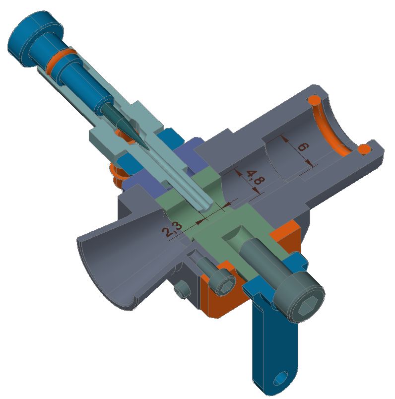
It took me some time to decide about the free section dimension. First of all, the intake ways of my engine should remain as they are. Second, I would like to use the carb on my next motor which will get a slightly larger displacement (at least for the first testing). So I made a 6mm (0.24in) main bore again with a venturi restriction to 5mm (0.2in). My thought was, that with a sliding barrel, the shape of the gas passage could still work well, even if the throttle is only half way (or three quarter) open at full speed.
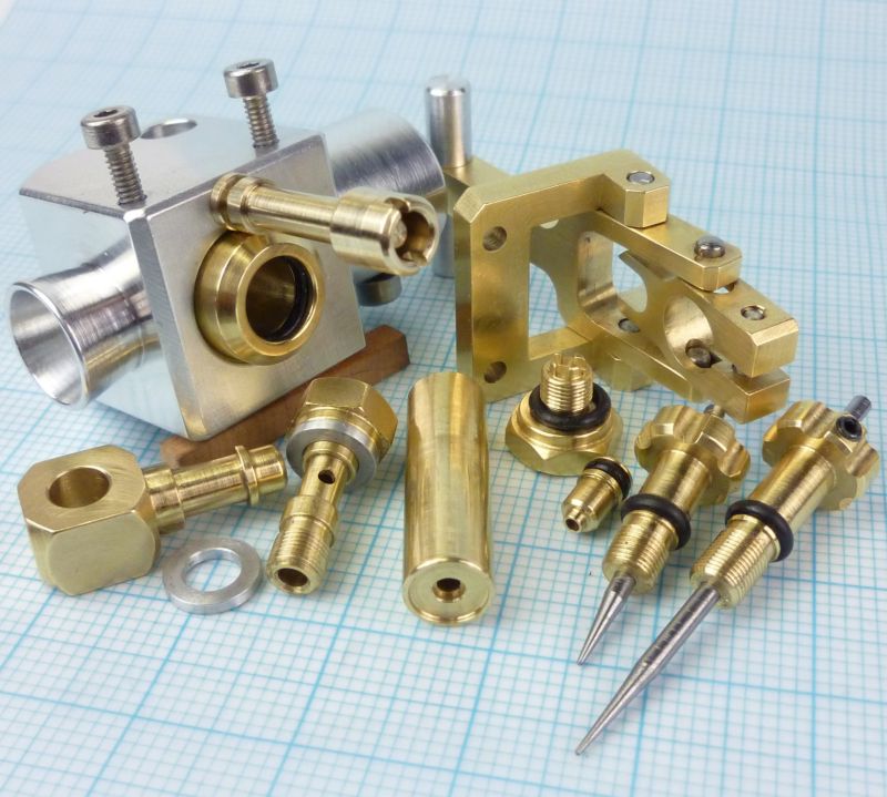
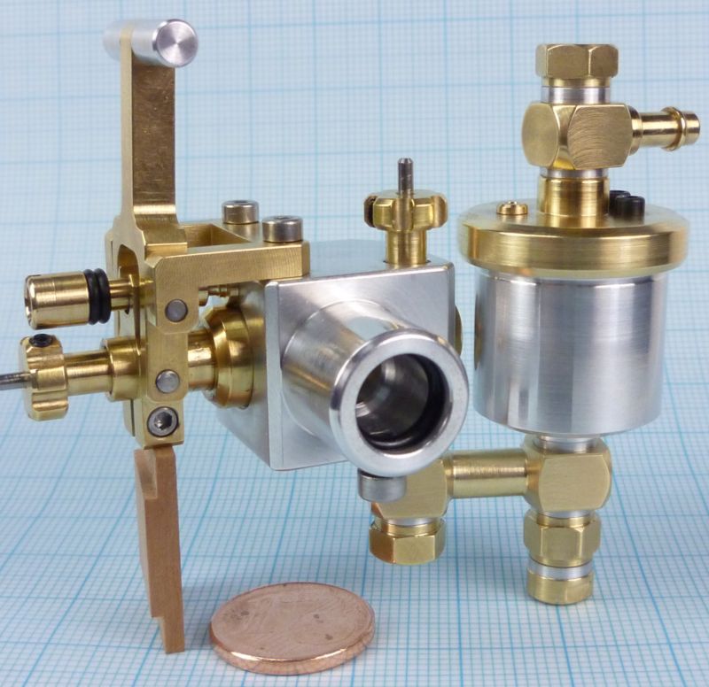
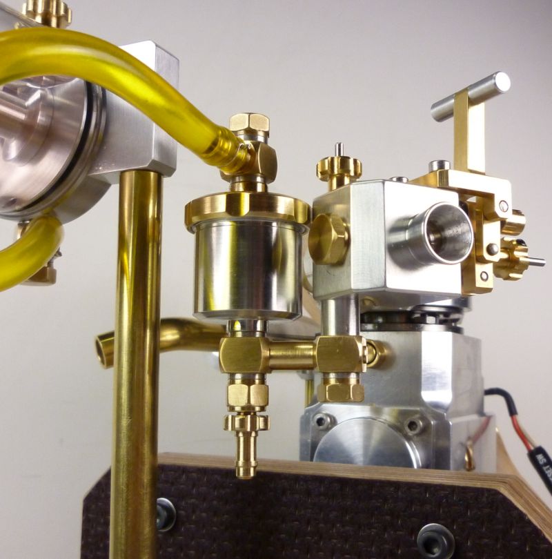
Here comes the inner life of my construction:
From the float needle valve the fuel flows through the float chamber and reaches the main body from underneath into an upright channel which contains the main mixture needle on its top. This needle has a 10deg cone and is driven by a fine pitch screw for a sensitive regulation.
From the main needle it goes over to the backside of the fuel jet tube. This little, single tube is held by a plug screw and easy exchangeable for further experiments with its functional proportions. All parts are sealed with o-rings, only a little bit more effort while building it, but no more problems with fuel and (more important because hard to detect) air leakage afterwards.
The remaining part is the sliding barrel type throttle valve, it goes with 6mm (0.24in) diameter through the 5mm (0.2in) venturi bore. The idle and half speed needle is also easy exchangeable, it is obvious that this needle might need a lot of experimenting to find the right shape and dimension later on.
End of part one
as fabulous George has started this very informative article about carburators some weeks ago I like to show you the new carb version I have designed a month ago for my latest 0.25 cubic inch 4-cycle gasoline driven engine.
My first version was a simple carb like the radio control people use on there methanol engines. I was inpatient and wanted to get the engine running, so I wasnt in the mood for long experiments and complex extra craftsmanship on this marginal component, but this was far wrong .ha ha ha .
The main dimensions are 6mm (0.24in) of free air passage and a reduced venturi area of 4.8mm bore (0.19in) in the rotating barrel type throttle.
I didnt last long to notice, that this arrangement was not the first choice for my need. Okay, the engine started from time to time, but it doesnt want to run longer than 20 seconds or so and it showed a lousy idle behaviour. Additional the gasoline level had a prominent influence on the whole function, being to low starting was nearly impossible, hanging the reservoir too high means the permanent danger of over floating the intake area.
Okay, to get at least any results with the existing material I tried to modify the venturi area. I made the fuel jet cylinder larger in diameter (from 2.4 up to 3mm) and let it now reach completely into the other side of the throttle barrel which means a quite heavy reduction of free section.
As George already mentioned, we tend to oversize the intake dimensions of our little gasoline motors, especially when we refer to comparable methanol engines. So, with this reduced width my engine was running a lot better. Suddenly I was able to speed up over 7000 rpm, could make long runs of 10 minutes ore more and the idle control was bearable too.
What left was a quite lousy starting behaviour, sometimes immediately running and then on other times it could drive me crazy, and the old problems with the influence of gasoline level.
My idea was that especially for the starting procedure the fuel jet needs the right fuel pressure. As the intake volume has only a small amount the vacuum from the venturi is too weak for the right starting mixture. It seems, that venturi proportions which are suitable for full throttle run dont work good for starting the engine at nearly idle setting. There is simply too little sucking on the fuel passages.
Okay, about three months after finishing the main engine I designed a complete new carburator .ha ha ha .
The new one is a mixture of a simple motorcycle type and a two needle methanol motor carb. It has a sliding barrel type throttle which contains the linear travelling idle needle and it got a float chamber too.
It took me some time to decide about the free section dimension. First of all, the intake ways of my engine should remain as they are. Second, I would like to use the carb on my next motor which will get a slightly larger displacement (at least for the first testing). So I made a 6mm (0.24in) main bore again with a venturi restriction to 5mm (0.2in). My thought was, that with a sliding barrel, the shape of the gas passage could still work well, even if the throttle is only half way (or three quarter) open at full speed.
Here comes the inner life of my construction:
From the float needle valve the fuel flows through the float chamber and reaches the main body from underneath into an upright channel which contains the main mixture needle on its top. This needle has a 10deg cone and is driven by a fine pitch screw for a sensitive regulation.
From the main needle it goes over to the backside of the fuel jet tube. This little, single tube is held by a plug screw and easy exchangeable for further experiments with its functional proportions. All parts are sealed with o-rings, only a little bit more effort while building it, but no more problems with fuel and (more important because hard to detect) air leakage afterwards.
The remaining part is the sliding barrel type throttle valve, it goes with 6mm (0.24in) diameter through the 5mm (0.2in) venturi bore. The idle and half speed needle is also easy exchangeable, it is obvious that this needle might need a lot of experimenting to find the right shape and dimension later on.
End of part one
Joachim Steinke
Active Member
- Joined
- Jun 14, 2010
- Messages
- 29
- Reaction score
- 22
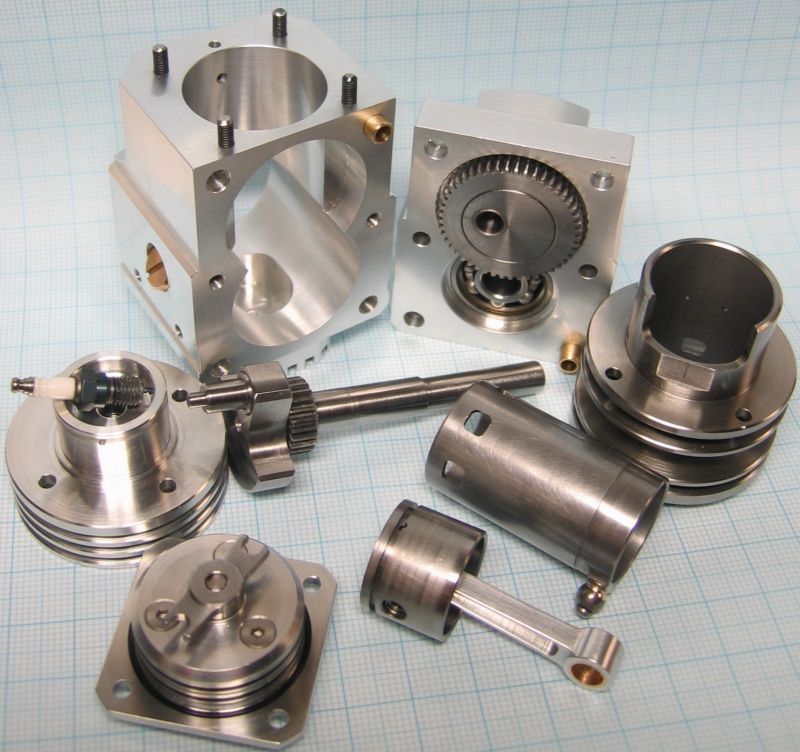
Part two
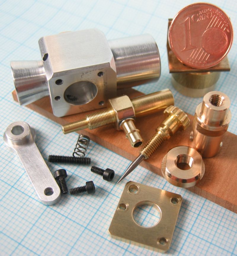
Okay, now its time to have a look at the real parts. They are made of high strength aluminium (7075) and brass, the valve needles are made of 1.5mm (0.06in) carbon steel.
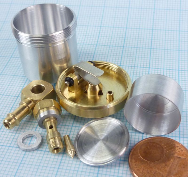
The aluminium float is manufactured with a wall thickness of 0.01in first and after glueing both parts together with epoxy I reduced the material down to 0.003in by turning it from the outside.
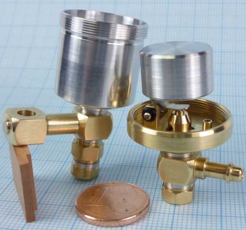
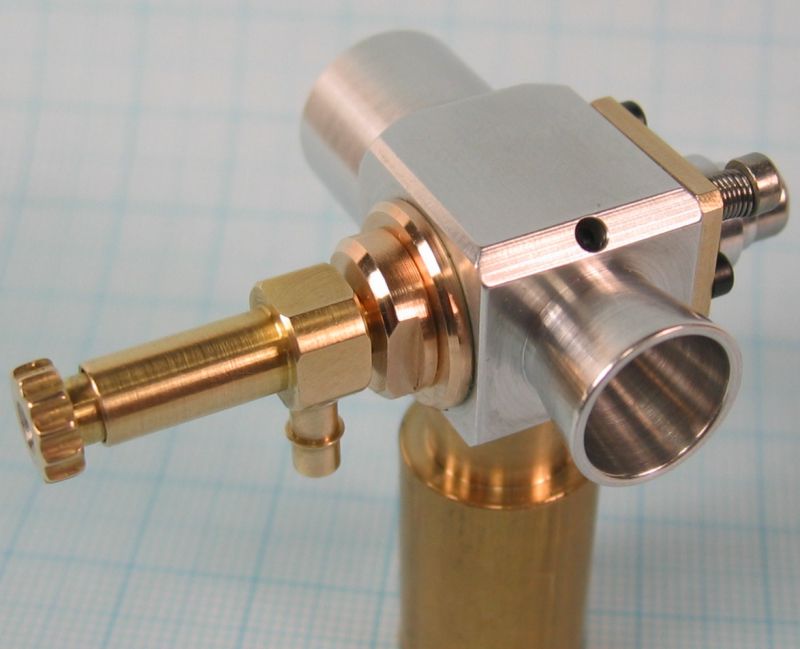
And finally assembled it looked like that:
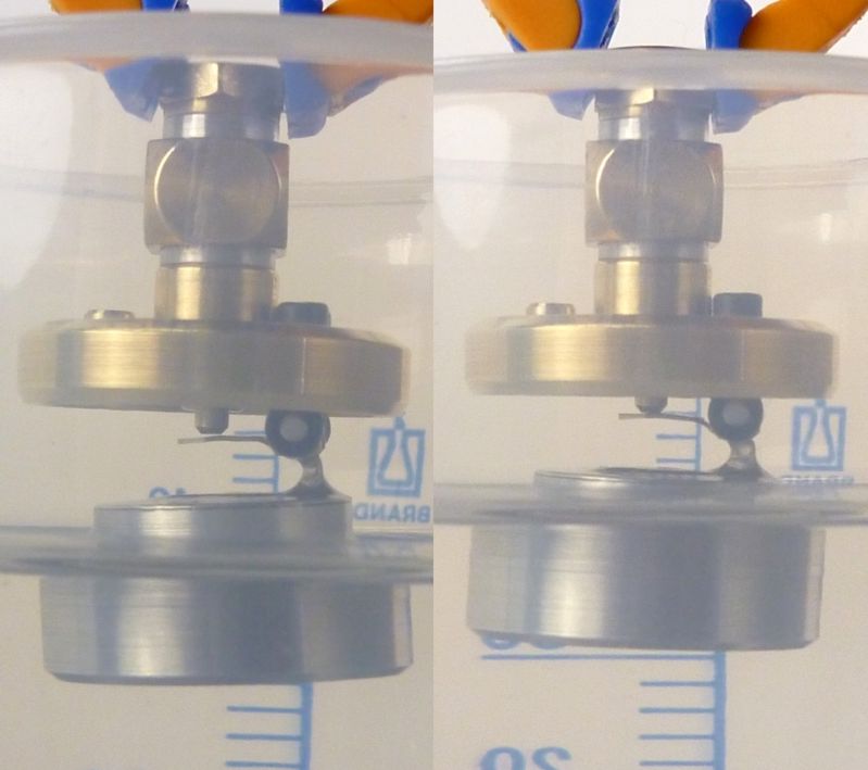
Next came the testing of the float. Its dipping to 85%, which will be okay for its duty, but you can see why I had to reduce the weight so extreme. With such a small displacement (resp. a small float diameter) the ascending force is very small too. To enhance the closing force a little bit I actuate the valve by a small lever arm.
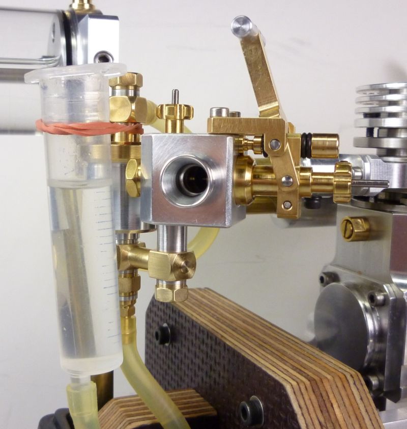
Now I could fix the fuel level. I have made an extra hose connector at the underside of the float chamber, so I can easy read the true level in the chamber. I then set the level about 0.04in under the fuel jet centre by building a suitable distance tube for the main body connection. The hose connector is also very useful for venting the float chamber when filling the whole system with fuel.
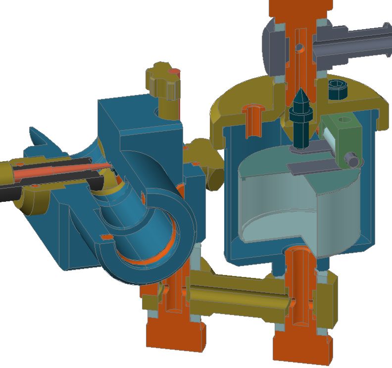
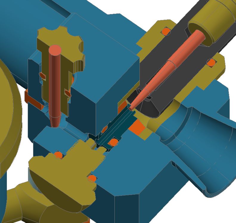
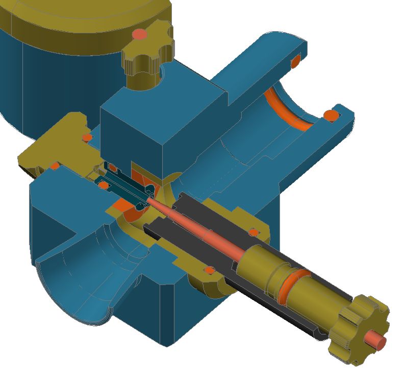
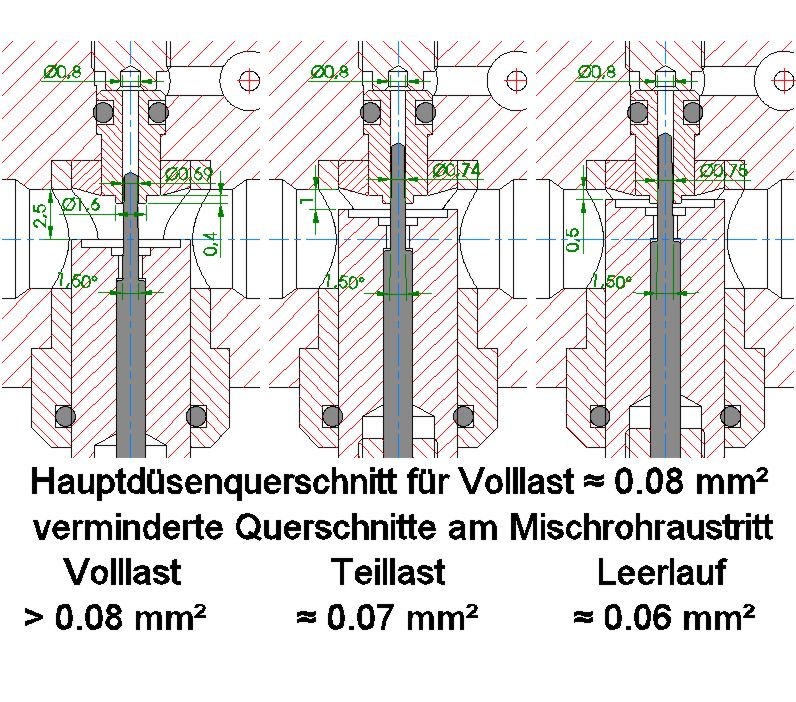
At last I had to think about the right shape of the idle needle. Here is a view inside the venturi at all four throttle positions
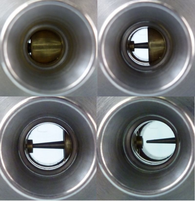
and a section through the complete system.

As the barrel travel from idle to half speed is only about 0.03in the needle has to be very slender.
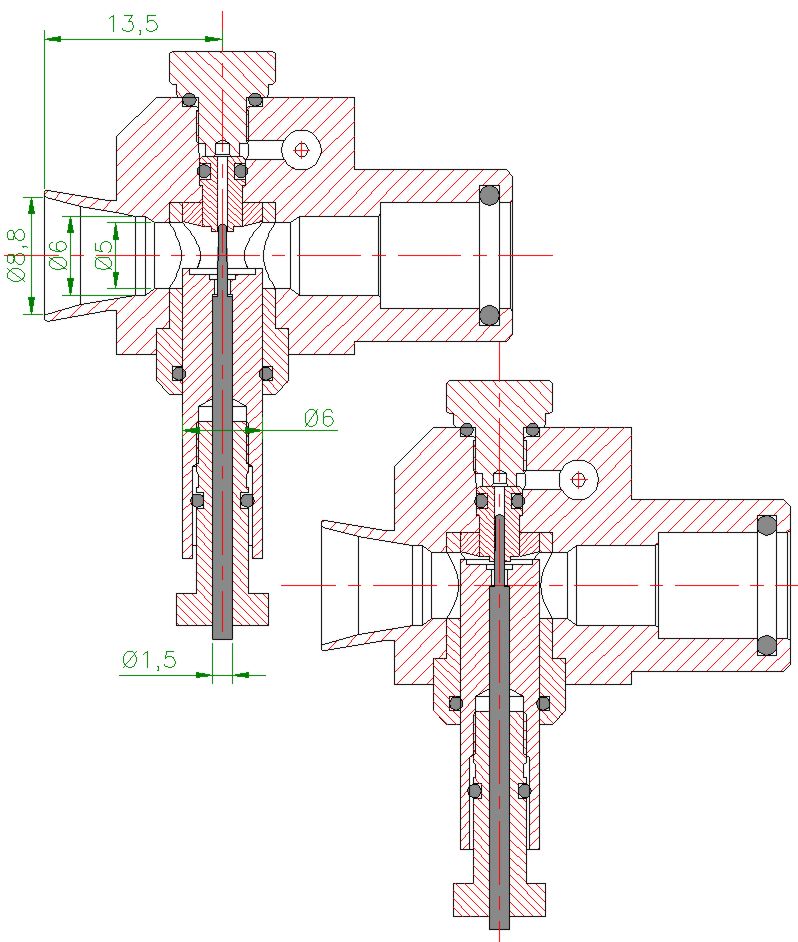
To get an idea of a suitable shape and cone angle I first calculated the cross section of the main fuel valve. I have an opening of this valve (for a good full speed) up to 300deg from totally closed. Knowing the main needle cone and the screw pitch I could get an approximate value of the main valve aperture.
The aim for my first tryout was to use a cone which reduces the via main valve available fuel flow within the barrel travel from idle to half speed in the range of 25%. That leads to a needle cone with 1.5deg and a max. diameter of 0.03in. The principle is shown here, sorry for the German inscription, but I think you can get an idea of the whole thing anyway.
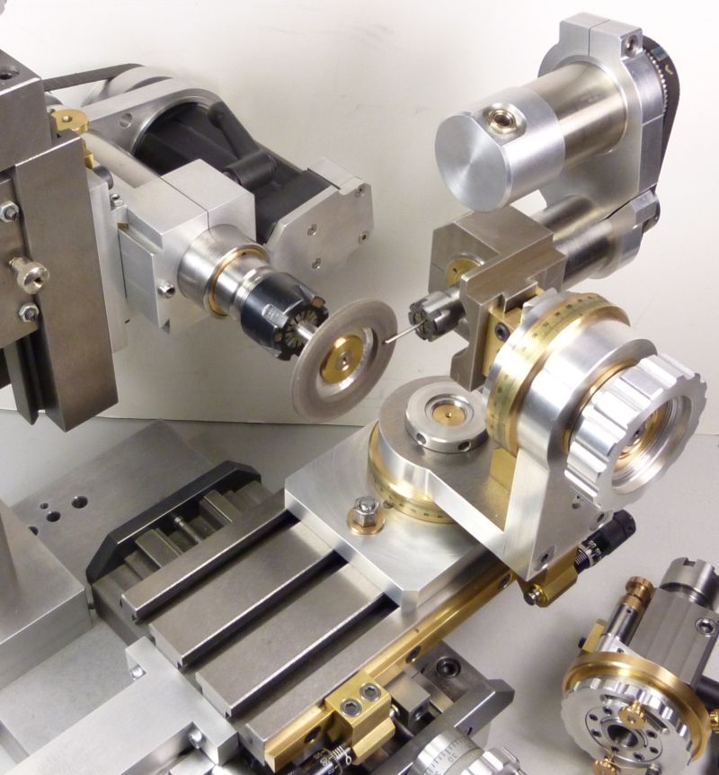
The grinding of such small and slender needles is always a bit fiddly. Fortunately I had build a small universal tool and cutter grinder last year at which I can install a second driven spindle. With this equipment a precise needle grinding is easy to do. But otherwise this can be done with a Dremel on the lathe as well.
Okay, now it was time for the final commissioning. It took a lot of patience to get the engine running with this completely new system, too many parameters to maintain ha ha ha
But finally I managed to get a perfect full speed run (with still fully retracted idle needle), after that it was quite easy to find a good position for the needle to take the desired effect of leaning the mixture more and more towards idle position. In addition and of particular importance the starting problems are vanished. For the cold engine I have to choke (finger closes the intake) one turn and can start at half throttle with a couple of turns then. And with hot motor it will do some turns at idle position before switching to half throttle.
I dont know if this carb is the ultimo ratio .ha ha ha ., but Im a good way satisfied with the result.
Okay, after a really long and boring post Im closing with two videos showing the new carb operating on the motor
http://pl-hi.de/JST/SLVE/SLVE_RUNNING_CARB_II_01.mpg
http://pl-hi.de/JST/SLVE/SLVE_RUNNING_CARB_II_02.mpg
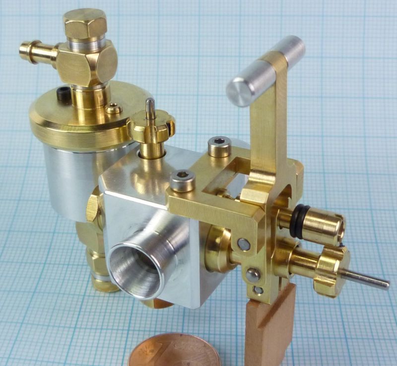
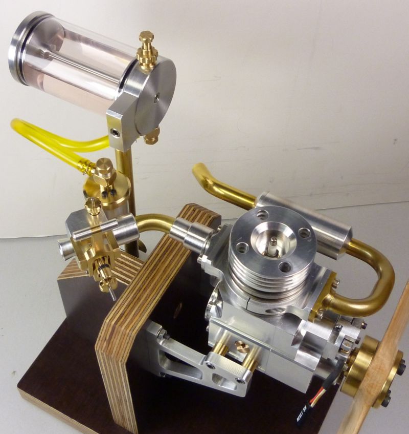
and two pictures of the now nearly completed engine.
Achim
Okay, now its time to have a look at the real parts. They are made of high strength aluminium (7075) and brass, the valve needles are made of 1.5mm (0.06in) carbon steel.
The aluminium float is manufactured with a wall thickness of 0.01in first and after glueing both parts together with epoxy I reduced the material down to 0.003in by turning it from the outside.
And finally assembled it looked like that:
Next came the testing of the float. Its dipping to 85%, which will be okay for its duty, but you can see why I had to reduce the weight so extreme. With such a small displacement (resp. a small float diameter) the ascending force is very small too. To enhance the closing force a little bit I actuate the valve by a small lever arm.
Now I could fix the fuel level. I have made an extra hose connector at the underside of the float chamber, so I can easy read the true level in the chamber. I then set the level about 0.04in under the fuel jet centre by building a suitable distance tube for the main body connection. The hose connector is also very useful for venting the float chamber when filling the whole system with fuel.
At last I had to think about the right shape of the idle needle. Here is a view inside the venturi at all four throttle positions
and a section through the complete system.
As the barrel travel from idle to half speed is only about 0.03in the needle has to be very slender.
To get an idea of a suitable shape and cone angle I first calculated the cross section of the main fuel valve. I have an opening of this valve (for a good full speed) up to 300deg from totally closed. Knowing the main needle cone and the screw pitch I could get an approximate value of the main valve aperture.
The aim for my first tryout was to use a cone which reduces the via main valve available fuel flow within the barrel travel from idle to half speed in the range of 25%. That leads to a needle cone with 1.5deg and a max. diameter of 0.03in. The principle is shown here, sorry for the German inscription, but I think you can get an idea of the whole thing anyway.
The grinding of such small and slender needles is always a bit fiddly. Fortunately I had build a small universal tool and cutter grinder last year at which I can install a second driven spindle. With this equipment a precise needle grinding is easy to do. But otherwise this can be done with a Dremel on the lathe as well.
Okay, now it was time for the final commissioning. It took a lot of patience to get the engine running with this completely new system, too many parameters to maintain ha ha ha
But finally I managed to get a perfect full speed run (with still fully retracted idle needle), after that it was quite easy to find a good position for the needle to take the desired effect of leaning the mixture more and more towards idle position. In addition and of particular importance the starting problems are vanished. For the cold engine I have to choke (finger closes the intake) one turn and can start at half throttle with a couple of turns then. And with hot motor it will do some turns at idle position before switching to half throttle.
I dont know if this carb is the ultimo ratio .ha ha ha ., but Im a good way satisfied with the result.
Okay, after a really long and boring post Im closing with two videos showing the new carb operating on the motor
http://pl-hi.de/JST/SLVE/SLVE_RUNNING_CARB_II_01.mpg
http://pl-hi.de/JST/SLVE/SLVE_RUNNING_CARB_II_02.mpg
and two pictures of the now nearly completed engine.
Achim
- Joined
- Jul 16, 2007
- Messages
- 2,985
- Reaction score
- 1,050
Hi Joachim,
That is a piece of jewelry if I ever saw one. What a great job you did on that carburetor. I like your idea of making the float. I have tried several different ways of building them but never had much success, not the building part but getting enough force to close the needle properly.
I tried a small RC truck carb which is somewhat like a motorcycle carb in that it has a sliding barrel to change the venturi area and it has a needle attached which pulls out of a needle jet. I think the problem with it was that the needle and jet weren't the right proportions for proper fuel metering.
Isn't it great when you get these little engines running like they should?
Maybe you could make up a drawing for your carb for those who would like to try building one. I for one would certainly like to try.
Thanks again for your comprehensive building information.
George
Lakc
Well-Known Member
Simply beautiful, or perhaps, a better word would be henreißen?
Most commercial carburetors are built with three main circuits, idle, midrange, and cruise. You seem to have done quite well here emulating this.
Most commercial carburetors are built with three main circuits, idle, midrange, and cruise. You seem to have done quite well here emulating this.
Joachim Steinke
Active Member
- Joined
- Jun 14, 2010
- Messages
- 29
- Reaction score
- 22
Hallo George,
first of all, thanks a lot for your appreciation. I observe your building logs and other publications related to IC engines for a long time now and consider you as a real distinguished model maker and engine builder.
Especially your new 90deg v-twin engine fascinated me so much that I was always impatient waiting for the next continuation of the report ha ha ha .. Beside a straight and clear functional inner design it is your detailed and harmonious shape forming of the housings (without using any castings and CNC either!) that create the particular character and excellent appearance of your model engines.
And YES, you are right, its worth all the work and technical difficulties when the little engine is running at last. To my opinion, nothing else can create such a fascination for a self developed piece of craftsmanship. And to the steam engine people, please dont take that too seriously .ha ha ha ! I have also designed and build a small steam engine with real Stevenson gearing three years ago and had much fun to do this, but finally I found out IC engines are more fascinating for me ..everybody has to be different ..
To your problems with the needle seal of the float chamber:
I had the same concern owing to the closing force as you, but maybe I was only on the lucky side with my construction. First I wanted to make a long needle travelling through the whole floats centre and let the float be operated by this needle guidance, much like some simple bike carbs from the 50ties are designed. But this bike carbs are a lot bigger and I was in concern if the ascending force of the miniature float will be sufficient enough. In addition I remembered problems with such types of float chamber in my youth when repairing my own light motorbikes. If there is any misaligning or minor trapping in the needle guiding the valve tend to leak, especially under heavy motor vibrations.
So I decided to build this little tin lever arm which supports the float nearly without any unwanted interaction. But the efficient relationship of this lever is really small, perhaps 1:1.5 or 1:1.7. Depending on the drifting ascending centre and the also rotating mass of the swinging float (and its, in relationship, heavy mounting components) the exact value of the lateral point is not easy to define. Anyway, it was impossible to fit much more lever effect in this chamber dimension. The only way to do this is to build an integrated float chamber directly beneath the fuel jet and intake area like all modern bike carbs have. Then you can make a doughnut shaped float of greater diameter which gives you two advantages, more displacement and a lot more lever relation possibility. In addition, depending on the small distance of the lateral point to centre of the fuel jet, you will get a float which is working widely independent of the carbs position in 3D space. But as I dont want to power up a mini motorbike with it this aspect might be negligible.
The needle seat might be a critical point too. In such constructions the only support for opening the valve comes from gravity (0.1g, dont cough if holding it on the palm of your hand it might be gone forever .ha ha ha) and the little fluid pressure on the very small needle cross section. I made the valve seat in the brass connecting screw with a 60deg centre bore. Because I wanted only a small area of contact between the two parts the needle cone was then turned with a light undercut of 59deg.
My pressure lubrication system (a little gear pump) makes some trouble transporting too much oil via the sleeve valve circumference into the cylinder ports. So it is disabled and I run the engine with a 1:40 gasoline/oil mixture now. With the oil mixture I had some doubt if the needle valve will tend to adhere in the cone, but it works quite well. I think the vibrations of the engine will do a good job too, they generate some breakaway force which, in addition supports the needle movement and help the centring of the needle cone.
To your legitimate suggestion about publishing a complete technical drawing of this carburator:
I have not yet decided if I want to do this. First of all, for my own production needs I am used to work direct with my 3D CAD model. So normally I dont have automatically generated 2D plans which everyone can easily understand and which can be used as complete working plans. This has do be done and would afford some time to do it correctly.
On the other hand I believe my posts contain all the substantial information one should need. Unlike to some other people I dont make a mystery out of whats going on inside the little black box. The included plans show all construction principles in detail and mention all important functional dimensions. So nearly everyone should be able to design his own version of the shown component. By the way, I never wanted to build engines with other peoples plan, but that is my own personal attitude.
To my opinion the 1 to 1 copy of a single accessory like a carb is normally not very useful as the variety of your own environment will determine too many changes. For instance, if you have a differing displacement the venturi might need other dimensions followed by a different fuel jet design and last but not least a different idle needle shape.
I hope you can understand my attitude a bit.
Achim
Hello Achim,
You said in your post, this was a 4 cycle engine. Would you please tell us a bit about where the inlet and exhaust valves are located and how they are operated.
Your workmanship is just beautiful on this engine and carb.
Regards,
Chuck Kuhn
You said in your post, this was a 4 cycle engine. Would you please tell us a bit about where the inlet and exhaust valves are located and how they are operated.
Your workmanship is just beautiful on this engine and carb.
Regards,
Chuck Kuhn
Hello Achim,
A bit off-topic, I know :hDe: but in the first video, there´s a neat propeller the motor is driving. I don´t see any maker´s name, did you also make that yourself?
It seems to be a wooden "pusher" prop, as the Americans prefer to call it, or "Linksläufer". The motor seems to rotate clockwise (seen from the front). Most small ( and not only small...) aircraft motors run counterclockwise, so to get proper cooling to the motor, the prop must be a lefty, of course.
I´m also looking for a "left handed" wood propeller, about the same size as yours, but have been rather unlucky so far. So in case you did not make the prop yourself, where did you get it?
Your website and posts have given me hours and hours of pleasure, admiring the amazing things you have made. Respect!
Joachim Steinke
Active Member
- Joined
- Jun 14, 2010
- Messages
- 29
- Reaction score
- 22
Hallo Cidrontmg,
you are right, unusual to normal RC model motors the shown engine is running clockwise.
I couldnt find a wooden Linksläufer with this dimension (10, with approximately 7 pitch) on the market as well. And as I must have excess to the central collet nut (with a 10mm socket wrench), I need a relative large diameter of the midsection too, which is totally unusual for propellers of this dimension.
So I made two wooden propellers myself, a simple one from a beech wood piece and a fancy one from precious wood. For that I glued 6 layers of pear and maple veneer (each of 2mm thickness) together, the rest is pure manual work with different rasps and some sanding paper, a nice job while watching the usual boring TV .h ha ha ..
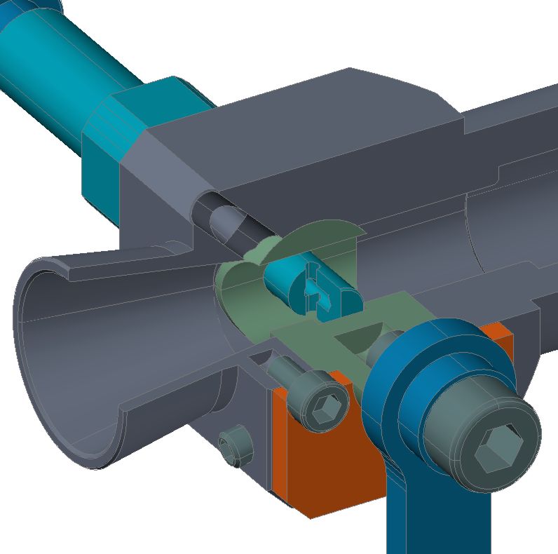
@Chuck: This engine has no poppet valves, the intake and exhaust is operated by a single sleeve that performs a rotary and shifting oscillation around the piston. This, in the English language area so called sleeve valve timing, is similar to, for example, the system Bristol Motor Company used in there famous Hercules and Aquila radial engines 70 years ago.
In this drawing you can see the dark grey sleeve which is located between piston and main cylinder. The movement comes from the little ball link, driven by the timing shaft gear which is similar to a cam shaft in usual engines.
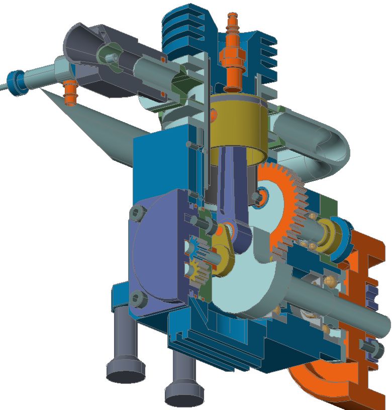
The best way to get an idea of the working mechanism is to have a look at this animation which I have made while thinking about my design:
http://pl-hi.de/JST/SLVE/SLVE_PORTS_02.wmv
With this information it might be easier to understand the function of the single parts shown here:
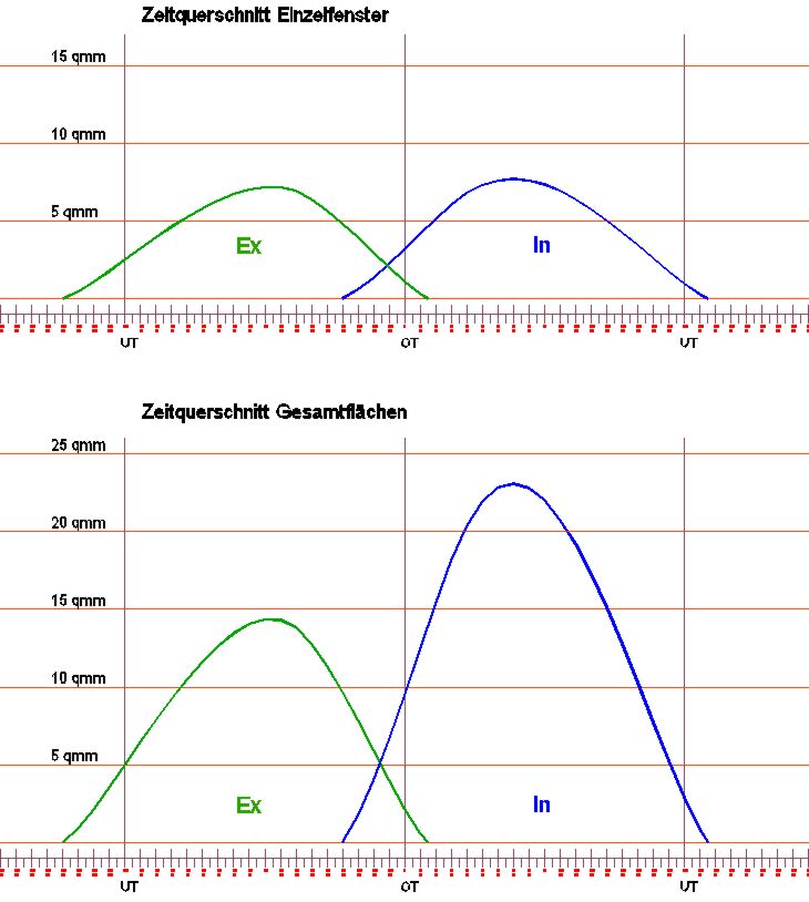
And this is the timing diagram and the port location in a flat projection of the cylinders circumference:
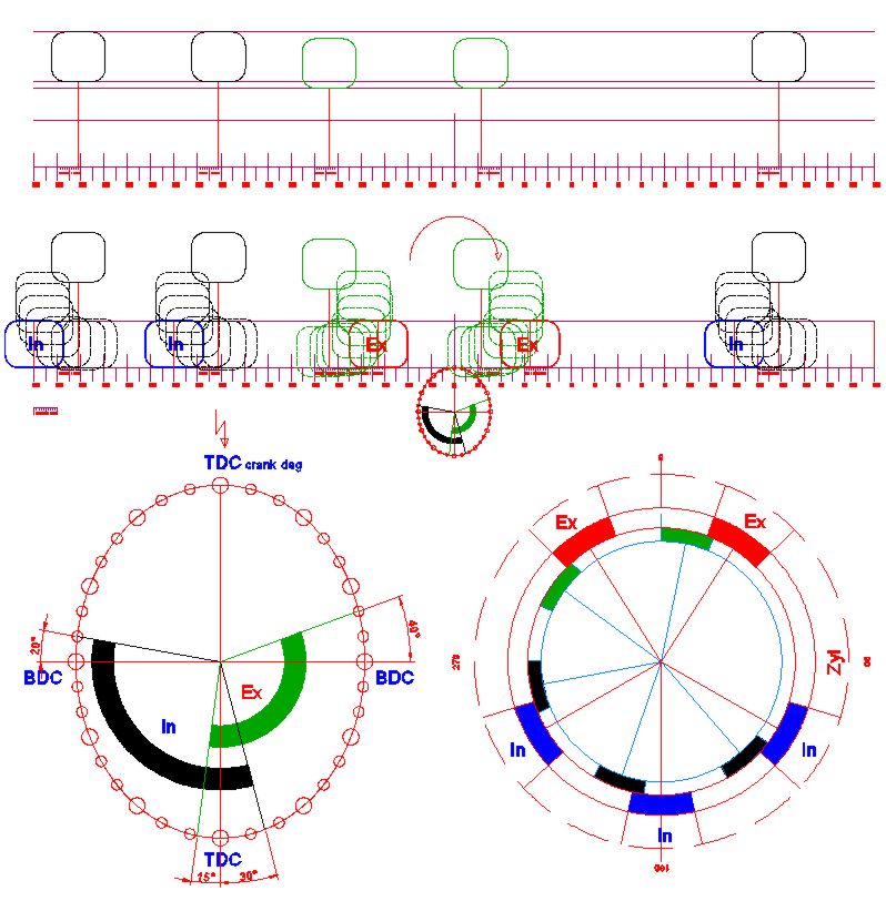
what leads to a port cross section loop over crank degrees looking like this:
But I dont want to bother this topic about carburators too much with more details about my sleeve valve engine. You can have a look at a complete report on my web site, sorry, the text is in German only
http://www.metallmodellbau.de/
or for instance on Mad Modder Forum, where I also published a full length building report in the building logs area.
Achim
you are right, unusual to normal RC model motors the shown engine is running clockwise.
I couldnt find a wooden Linksläufer with this dimension (10, with approximately 7 pitch) on the market as well. And as I must have excess to the central collet nut (with a 10mm socket wrench), I need a relative large diameter of the midsection too, which is totally unusual for propellers of this dimension.
So I made two wooden propellers myself, a simple one from a beech wood piece and a fancy one from precious wood. For that I glued 6 layers of pear and maple veneer (each of 2mm thickness) together, the rest is pure manual work with different rasps and some sanding paper, a nice job while watching the usual boring TV .h ha ha ..
@Chuck: This engine has no poppet valves, the intake and exhaust is operated by a single sleeve that performs a rotary and shifting oscillation around the piston. This, in the English language area so called sleeve valve timing, is similar to, for example, the system Bristol Motor Company used in there famous Hercules and Aquila radial engines 70 years ago.
In this drawing you can see the dark grey sleeve which is located between piston and main cylinder. The movement comes from the little ball link, driven by the timing shaft gear which is similar to a cam shaft in usual engines.
The best way to get an idea of the working mechanism is to have a look at this animation which I have made while thinking about my design:
http://pl-hi.de/JST/SLVE/SLVE_PORTS_02.wmv
With this information it might be easier to understand the function of the single parts shown here:
And this is the timing diagram and the port location in a flat projection of the cylinders circumference:
what leads to a port cross section loop over crank degrees looking like this:
But I dont want to bother this topic about carburators too much with more details about my sleeve valve engine. You can have a look at a complete report on my web site, sorry, the text is in German only
http://www.metallmodellbau.de/
or for instance on Mad Modder Forum, where I also published a full length building report in the building logs area.
Achim
Achim, thank you for the photos, 3D models, and link to your website. I had not considered the engine might have a sleeve valve.
Regards,
Chuck Kuhn
Regards,
Chuck Kuhn
Admiral_dk
Well-Known Member
- Joined
- Jul 15, 2010
- Messages
- 166
- Reaction score
- 0
Hello Joachim
I'm very impressed with your "vergasser" / carburator construction, it's a lot like the old Del'Orto that we had in my youth for 50-250cc motorbikes. They wheren't easy to optimize, because of the horizontal orientation of the mainjet, needle and throttle valve. The good part was that they worked in almost all orientations of the venturi.
I wouldn't be surprised if you can improve the design a bit by turning the throttlevalve to vertical and experiment with the exact fuel level - how many mm. below the venturi. Modern motorcycle carburators have a "pre-mix" function in the needle jet, where air from the outside is drawn into the jet and mixet with the fuel from below and sucked up into the venturi and I wonder if this could be done in the smal scale and stil work as an improvement too.
Then there's direct injection and I got drawings on how it's done in model size and it works - unfortunately in a book and therefore under copyright ....
The princip is simple : A leaky gear pump is used, as the revs rise, the pump get's less and less leaky because of the fuels resistance to movement. This increase the preasure and amount supplied to the engine in an almost perfect relation to how much is needed. The size of the gear and the leak (distance between gears) is the important measurement. It's important to have return valves in the system too, in order to prevent air in the system - he used simple ball and spring valves. I'm sorry to say that he do NOT publish any formula for calculating the gears.
- Joined
- Jul 16, 2007
- Messages
- 2,985
- Reaction score
- 1,050
One of the problems in designing a carburetor for these small engines is that most of the engines that are scratch built are unique. By that I mean each one could have different valves sizes, port diameters, port lengths and type of cooling would also have an effect. A carburetor that will be fine tuned to run on one engine might not work so well on another.
With hit & miss engines the rpm is somewhat constant so the design of the carb can be quite simple, a venturi and a fuel control needle and port. As we have discussed previously, generally the smaller the venturi is the higher the air velocity and therefore the better fuel atomization.
The next step up would be engines that run at 2 speeds, idle and high speed, much like a utility engine that would be found in a lawnmower or some similar implement. The old Briggs type engines had very rudimentary carbs, no float, just a dip tube that went into the tank from which the fuel was drawn into the idle port during high vacuum and into the main venturi during high speed operation.
What we are asking our little engines to do is run well, and clean, throughout the rpm operating range. This calls for a more sophisticated type of carb, much like Achim has presented. In most cases it's not the machining of the individual parts that causes the problems but rather having no way of measuring how rich or lean the mixture is at any given rpm.
If anyone has ever 'tuned' a carb the procedure is to warm the engine, run the rpm up and adjust for the highest, or cleanest rpm. Once that point is achieved the needle is then turned around a quarter of a turn to the rich side. The reason being that if you leave it where it runs the best it's on the verge of being lean and you can harm the engine. Next you bring the engine speed down to a point where it will run as slow as possible without stalling and do the same as you did for the high speed adjustment. This works fine for an engine with a 2.00 inch or larger bore because if you're a little on the rich side the engine can tolerate it but when working with our small engines the fuel control has to be so precise because they won't tolerate either a rich or lean condition for very long.
As for using a fuel injection system of the type that Admiral_dk describes, yes it will work but as I started out saying each engine is unique and has specific fuel requirements. Now add in the equations of how loose to make the gears and what size jetting to use just adds to the complexity. And for the statement that as the rpm increases the fuel is provided at just the perfect relationship, this might be so but on an engine with what specifications.
I haven't read of or spoken with anyone that has come up with the definitive solution for model engine carburetion. It all takes a basic carb design and then a great many hours of tinkering.
George
Lakc
Well-Known Member
gbritnell said:In most cases it's not the machining of the individual parts that causes the problems but rather having no way of measuring how rich or lean the mixture is at any given rpm.
Thats an easy fix from back in the early days of US auto emission controls. Chrysler used to publish and subscribe to the "propane enriched idle" method, where the idle mixture was set at a specified rpm, and expected to increase X amount of rpm when a metered amount of propane was introduced to find the "best rich" setting.
For example, an engine idle rpm was set at 650, with a propane enriched figure given of 725. You would set the idle mixture at best rich and the idle rpm to 725, then lean the mixture out until 650 rpm was reached. Adding propane down the carburetor in the correct amount would jump the idle speed back to 725 verifying you had legally set the idle mixture.
Propane will replace any fuel in an IC engine at any rpm. If you think your lean, add a little propane and if the rpm goes up, you are, if the rpm goes down, your perfect or rich already. The trick is only in having a fine enough adjustment to meter the propane with. Butane cigarette lighters might even be more appropriate for small engines.
The really tricky part is the nearly logarithmic scale that fuel needs to be added with LOAD at a given rpm. The only load we have on a display engine is the crankshaft, flywheel, and pistons themselves. Bolt on a propeller or some other load and making an engine do some work will take a variable load like a dynamometer along with propane to straighten out the carburation.
I think the issue with engine that are run with no load is low intake tract velocity. Surely a carb that is sized to give a reasonable RPM at WOT gives plenty of venturi velocity. But, velocity in the runners is low and there is probably a significant amount of fuel condensing on the walls. This delays the response of the engine to needle setting substantially. The problem is much worse when the engine is cold and requires enrichment to start and run. A separate fuel circuit that could be turned on when needed for enrichment might be a good idea. Walbro carbs are fairly simple. The fuel demand regulator (the diaphragm) replaces a float. Otherwise it's just a 2 circuit carb, but one that has been engineered for the flow conditions encountered in the engine it's on.
In a model engine the correct idle rich setting is one that allows a good transition to high throttle without stalling. These carbs have no acceleration pump, so fuel must already be in the intake manifold due to rich idle mixture when you crack the throttle open. It takes a certain amount of time for this fuel to accumulate and dissipate at various operating conditions, so it's always a compromise. Chasing needle setting without understanding this could lead to a headache. Most model engines are run very rich. Ideal mixture for model engines loaded or not is performance based, not emissions related. The mixtures are set so the engine performs as expected, rather than to meet a certain air-fuel ratio or other specification.
You could run it as lean as you want it's not going to detonate unless maybe you're fueling it with kerosene. You can't run it too rich because the low flow will load up the intake.
The biggest problem I've found when burning kerosene or gasoline is the change in required mixture for a cold engine. If you tune a simple carb for a hot engine it will run poorly until the engine is up to operating temperature. This can take quite a long time. I have an OS FS-52 glow four stroke converted to diesel. Loaded up with a big prop running about 4000 RPM at wide open throttle, it takes well over a minute to reach full temperature. The mixture requirement constantly changes during warm-up, but setting the idle rich will usually tolerate the cold to hot range.
Admiral, do you by chance have a title for the book with the fuel injection details?
Admiral_dk
Well-Known Member
- Joined
- Jul 15, 2010
- Messages
- 166
- Reaction score
- 0
Hi DieselPilot
Yes I've got it at home and it's in German .... It's about building multicylinder model engines, as in-line, Vee and Boxer. I've just Googled :
BUCHMTB33
MTB33-modell-technik-berater
Boxer, Reihen- und V-Motoren als Modell
Autor: Hubert W. Schillings
http://www.rc-machines.com/index.php?navi_1=product&navi_product_1=search&navi_product_2=techn&start=3
It's only a part of the carburation chapter, but you can see one of his injected models on the cover in the above link.
But perhaps you should consider getting the numbers if SIC where there's a build of a 10cc true diesel engine, including injector, pump and the works, if you're more into Diesels.
Similar threads
- Replies
- 8
- Views
- 687