Building Elmer's Fancy

Home Model Engine Machinist Forum

Help Support Home Model Engine Machinist Forum:

This site may earn a commission from merchant affiliate links, including eBay, Amazon, and others.
Thank you Rob and Bob for your interest & support!
I'm also itching to get "her" running! - about 60% complete? - the last 5% will take the most time ;)
Kind regards, Arnold
 
Nice progress! Looking good.

arnoldb said:
I'm also itching to get "her" running! - about 60% complete? - the last 5% will take the most time ;)

Yeah, how do they say it, " The first half of a project takes 95% of the time planned for completion, and the the last half takes the other 95%." ... or something like that. ;D
 
Thanks Vernon :)
Vernon said:
Yeah, how do they say it, " The first half of a project takes 95% of the time planned for completion, and the the last half takes the other 95%." ... or something like that. ;D
Oh yes, I learned that here on HMEM ;D - though I'm not exactly a statistician :-[ - Rof}
Regards, Arnold
 
arnoldb said:
Thank you Rob and Bob for your interest & support!
I'm also itching to get "her" running! - about 60% complete? - the last 5% will take the most time ;)
Kind regards, Arnold

Have you some idea in mined Arnold

Regards Rob
 
Your Fancy, she is coming along quite nicely Arnold. Well done.

BC1
Jim
 
Vernon said:
Nice progress! Looking good.

Yeah, how do they say it, " The first half of a project takes 95% of the time planned for completion, and the the last half takes the other 95%." ... or something like that. ;D

first 95 % of the task takes first 50% of the time, last 5% of task takes the other 50% of time

Redo takes, well we dont redo, do we :)

Robert
 
Foozer said:
first 95 % of the task takes first 50% of the time, last 5% of task takes the other 50% of time
Haha, yeah that's it, thanks, Foozer. ;D
 
This one is coming along great, Arnold. Good write up and photos too.
Thanks for sharing, and keep up the good work!

Dean
 
bearcar1 said:
Your Fancy, she is coming along quite nicely Arnold. Well done.

BC1
Jim

Thanks BC1! :)
Regards, Arnold
 
Deanofid said:
This one is coming along great, Arnold. Good write up and photos too.
Thanks for sharing, and keep up the good work!

Dean
Thanks Dean :) - I'll try my best ;)
Regards, Arnold
 
RobWilson said:
Have you some idea in mined Arnold
Rob, when you posted that, I didn't have much of an idea yet - I left one of my braincells pondering (I don't have many, so as a result I didn't get much done for the last couple of days ;D) When I started with Fancy, I wanted to make her, well, fancy - or at least as fancy as I can ::)

Now for the progress...

This morning I started on the crankshaft. I decided to use brass for the web, so chucked and faced a bit of 3/4" brass. Then I used my smallest center-drill to just touch the stock, to get the center. I marked out the web while mounted (the center dimple is needed for the compasses to get the crank pin offset). For marking out, I really like the Myford's flat bed-ways - a quick wipe over the bed (to get rid of swarf) and drop (well, carefully place) a square on the bed & mark out:
smaller-IMG_1202.JPG


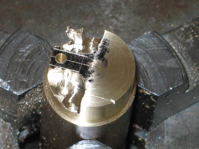
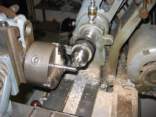
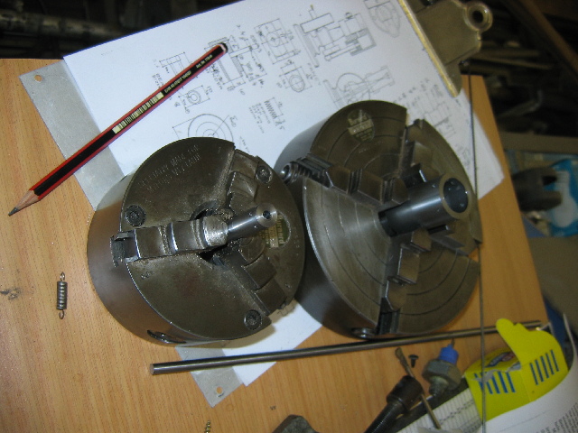
Then, using the toolpost as a "steady" for my wrist, I punched marks for the crank pin and for the holes to help machine the web contour. I decided to make the crank-pin hole and machine the contour on the web before parting it off, so I set up the vertical slide and dividing head, transferred the chuck, and drilled the needed holes:
smaller-IMG_1204.JPG


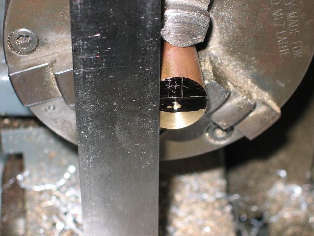
Then I put the the 4-jaw on the spindle with a centered 4mm bit and milled (well, gashed/hacked :hDe:) the web profile:
smaller-IMG_1206.JPG

Notice the deep scratch left on the web surface by the biggish chunk of brass (similar to the one still left in the top of the photo) breaking off. That was very nearly a sticky-brown-pants moment...

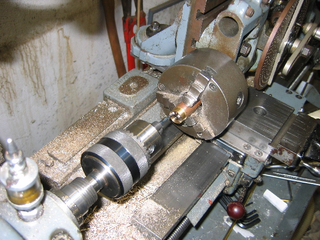
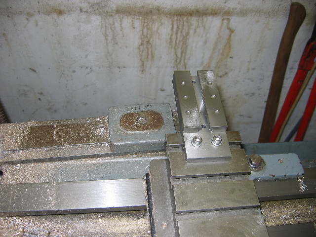
For now, I don't have a riser block for the dividing head to fit it directly to the short cross-slide, nor do I have any way of mounting the chuck more rigidly to the cross-slide. There is also no way to mount the dividing head directly to the vertical slide and get in the ranges needed to mill this job, so I had to resort to using a cross-slide extension I made about a year ago - hence the non-rigidity in this milling set-up:
smaller-IMG_1207.JPG


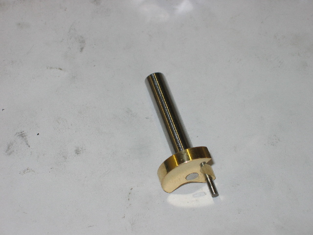
I then transferred the job back to the spindle, drilled the hole for the main shaft, faced off the scratch (fortunately I left some "meat"), and parted the web off. A quick turning job for the main shaft (from silver steel) to press-fit in the web with some "loctite", and then used my cheapy-Dremel-like tool to polish the web. The main shaft is handy for clamping the assembly in the big vice for polishing; shaft protected by a leather welding glove :). Then I cut some 2mm piano wire for the crank pin with the Dremel (I use my Real Dremel for more important jobs ;) ) and, thoroughly cleaned, I pressed it in (yes, with loctite :) ). It's easier to polish the web face first - without the crank pin in the way :big: ) - so, one crank done:
smaller-IMG_1208.JPG


If, by this point in reading, you haven't fallen asleep yet, I must compliment you on your tenacity Thm:

The singular braincell I left on duty for an idea eventually did have one! - make the flywheel from the cast iron specially obtained for the purpose, and mill 5 spokes in it with the flywheel locking pin and screw hidden inside of one of the spokes. Wow - brilliant idea :noidea: - except, after today's milling I'm not keen to repeat that! So I called a meeting between all the brain cells present (a couple were away chasing girls - I hope one of them gets lucky!).
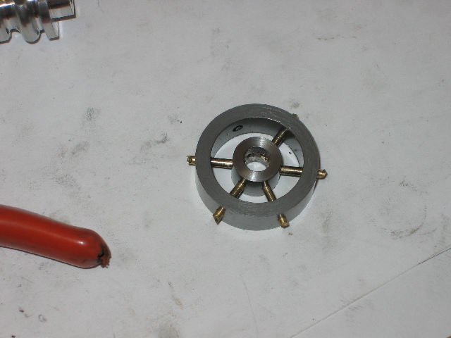
Once I was able to impress the importance of the matter on the present brain cells, they came up with nearly as an insane solution as the original - build a multi-part flywheel - "mystery metal tube" for the outer part - from an old printer, 6 brass spokes (one of which doubles as the flywheel locking screw) - made from 2mm "brass" brazing rod, and a 12mm hub made from silver steel.... INSANE, but what the heck, I'll try it; if it fails, I'll just make a "plain" flywheel...

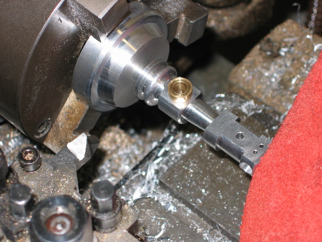
Center drilling the hub for one of the spoke locations - lots of 1.6mm holes after that :big: :
smaller-IMG_1213.JPG

Today was finished off with 2mm threads in each of the hub's spoke locations (except for the one "plain" 2mm hole in one location for the "locking pin/spoke"

Regards, Arnold
 
Very nice Arnold,looks like your Brain cells are in good working order ;D i see your ML7 has some good attachments,Dividing head and tapper turning attachment ,tool envy :big:
Regards Rob
 
arnoldb said:
So I called a meeting between all the brain cells present (a couple were away chasing girls - I hope one of them gets lucky!).

Your brain cells have an active life Arnold, just hope they don't form a union ::)

Nice work, the crank's turned out well
icon_salut.gif


CC
 
RobWilson said:
Very nice Arnold,looks like your Brain cells are in good working order ;D i see your ML7 has some good attachments,Dividing head and tapper turning attachment ,tool envy :big:
Regards Rob
Thanks Rob. Yes, I lucked out with the Myford - basically full kit, except for QC box and long crosslide. One thing I REALLY like about it is the clutch ;)
Have never used the TTA, but will soon have reason to. Fancy's done; next up will be some tool making, including 2MT collets; can't afford to import them :(

CrewCab said:
Your brain cells have an active life Arnold, just hope they don't form a union ::)

Nice work, the crank's turned out well
icon_salut.gif


CC
Thanks CC :) - I'm a dictator; No unions allowed in my head :big:
 
Well, Fancy is complete; didn't turn out quite as well as I wanted, but practice makes perfect...

This morning I finished the flywheel assembly: first time I can recall that I had both my lathe's chucks holding work-in-progress; 3-jaw with the hub-to-be and 4-jaw with the rim-to-be after getting drilled & tapped using the dividing head:
smaller-IMG_1215.JPG


Both were just parted of after above photo - the hub only after I drilled and reamed it to size for the axle.

Then I made the flywheel spokes from brass brazing rod, and threaded one end each for M2 to screw into the hub. These brazing rods are strangely difficult to get threaded; the die just does not want to "bite" to start, so I had to file a fairly significant taper on each before threading.
Then I assembled the lot with loctite on all the treads and the parts in the rim.
Hub assembled & excess rod crudely clipped off using side-cutters:
smaller-IMG_1216.JPG

To make up the missing spoke - which is also the locking pin, I shortened an M3 grub screw, and cut and filed a bit of brazing rod to the correct length for the assembly. Some of the spokes were intruding into the shaft hole, so I drilled the hole out in the drill press, then reamed to size again; that got rid of the protrusions. Then I turned the excess bits on the rim down in the lathe using the grub screw & lock-spoke to clamp to an arbor.
Polishing the spokes in situ to get rid of some excess loctite & dings from the installation nearly stumped me - but I settled on a leather thong coated with metal polish; one spoke at a time; this worked a treat ;) Unfortunately, it runs with a bit of an up-down wobble; can't figure out how to correct that :-[

Then I turned a base, and while still in the lathe, used the tailstock to press in the column. The red bit you see is a leather welding glove between the top of the column and the tailstock drill chuck to prevent damage to the top of the column:
smaller-IMG_1217.JPG


After this, I pressed in the steam pipe in the vice - once again using the welding glove to protect everything. I knew it was home when I heard a strange kgrtz sound; the pipe punched a neat hole through the glove & Ihad to fish out the round bit of leather from inside the pipe...

Then I (crudely) polished the cylinder block, cleaned everything, assembled with some thin oil, and gave it a trial run. Something's still a bit stiff, but at about 10 PSI she started up and ran. All brass components are polished; the flywheel is "semi" polished, and the aluminium column and base are as-machined.

I still wanted to make a nice nut for the pivot shaft and given everything a clear lacquer coat to protect it, but that will have to wait for now.

So here's Fancy (I hate my camera; it highlights the defects! :big: ):

IMG_1226r.JPG


IMG_1227r.JPG


I'm still struggling to upload the video of her running - will link to that as soon as it's done.
Movie: A bit of a big file :Here

I hope my effort is worthy of it's name! - and a BIG thanks to everyone who supported me through this build :bow: !
Kind Regards, Arnold
 
great job Arnold :bow: :bow: :bow: looks well with a spoke'd flywheel,very nice, what are you going to build now ? ? ? ? ;D
Regards Rob
 
Nice Arnold!
I almost missed this. I was gone when you started it.
Read the whole thread. Very worthwhile.
Thanks!
Can't wait for the video.
 
Thanks Rob & Zee :) - just added the video link, but a bit of a big file for a small video...

RobWilson said:
what are you going to build now ? ? ? ?
Rob, for now, I have some "Unfinished business" - that needs to get done, then some tooling is up for it... to make life easier!
After that, well, I'm kicking a couple of ideas around; still have to choose ;D

Zee - Your absence was very conspicuous FWIW I missed you on the forum! ;) Hope you had a good time overseas with the wife :)

Regards, Arnold
 
Thanks Arnold...I appreciate that.

Yes. Had a great time overseas.
She comes home for good in a week.
Hopefully I won't go missing again...but she's already got my time planned...weeding, home improvement, cleaning...all the things I was supposed to be doing while she was gone. ;D

Tried the video but it doesn't work for me. I'll try again later.
 
That does look well Arnold 8) ............ if those are the pictures with a "crap" camera it's gonna look dam good with a better one ;D

I like the flywheel, particularly the use of the grub screw to lock one spoke to the crank, I'll file that one away to copy borrow later :D

The video ain't working for me either I'm afraid :(

CC
 
Back
Top