Brian's Donkey Engine

Home Model Engine Machinist Forum

Help Support Home Model Engine Machinist Forum:

This site may earn a commission from merchant affiliate links, including eBay, Amazon, and others.
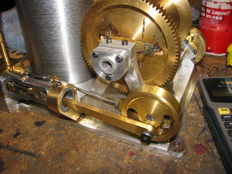
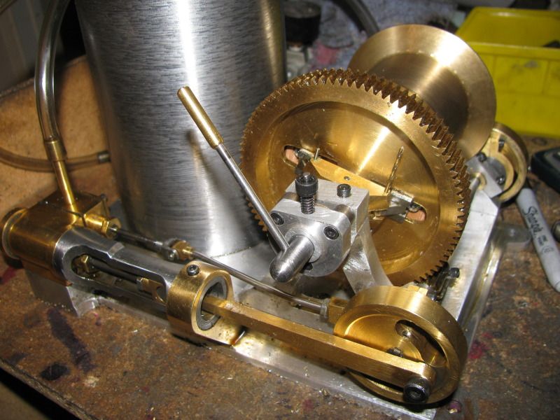
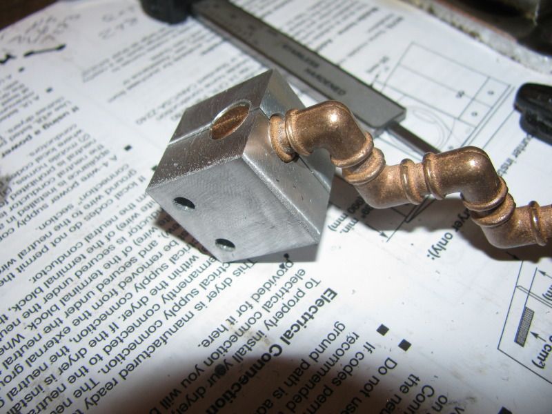
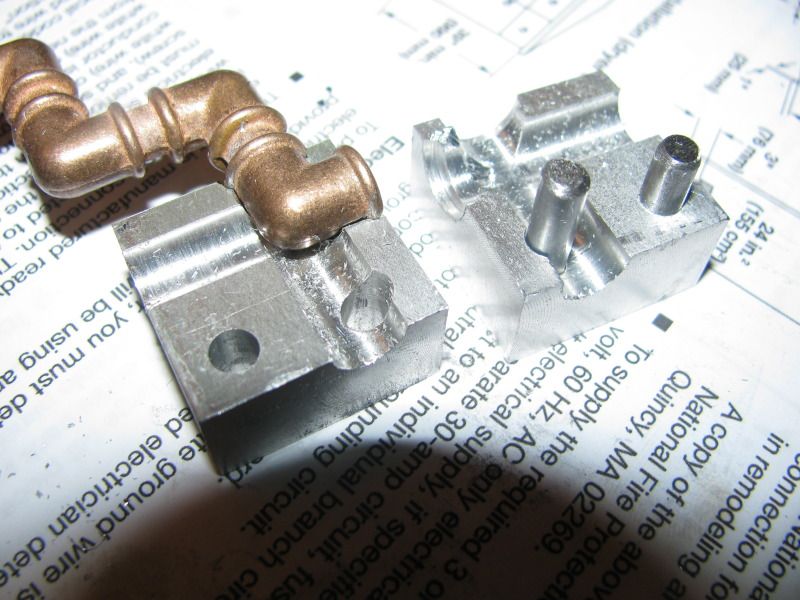
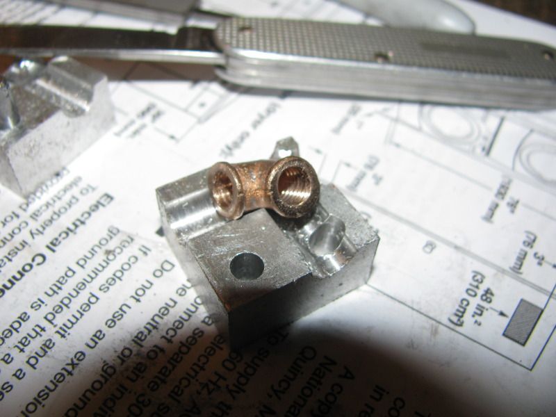
And another one bites the dust!!! I just finished the clutch activator block and bolted it onto the bearing stand to make sure all the bolts line up-----They did!!! As you can see from the grease around the clutch sliders, I have been "fiddling" with the clutch mechanism and now have it working much smoother. I did put a small compression spring inside the winch shaft which bears against the cross pin to ensure that the clutch disengages each time it has been engaged and it works much better now.
clutchactivatorblock001.jpg
 
Well, I have just about used up the whole day clutching. Wife finished the horrible income tax, and if all goes well, I think we only owe $11 to the government. This is the first year with both of us drawing pensions, and if we hadn't been able to do "Pension splitting, which is a relatively new thing in Canada, we would have had to pay $2000!!! Quite a difference!!---And if the Donkey Gods smile on me, I may have a video of the clutch operating tomorrow.
CLUTCHMECHANISMFINISHED001.jpg
 
Brian,
Trying to figure out how your clutch lever will work. I know on the full size Willamette I restored, the clutch lever turned a multi-start screw that moved the frictions in and out against the drum, but your drawing shows just a thru hole. Waiting to see what you have up your sleeve.

Brian
 
Here is a drawing of the spacer that acts as a "stand-off" between the bearing support and the clutch activator block.
CLUTCHACTIVATIONBLOCKSPACER-2.jpg
 
It just keeps getting better and better Brian. What a nice addition the little donkey will make to your already fine collection!! Looking forward to the clutch video as well.

Bill
 
Now, if you have a really good imagination, you can see what happens when all those parts are assembled. When the handle is swung thru an arc, the 3/32" pin loctited into the center of the #10-24 shcs is always engaged with that slot, forcing the rotating pin to move foreward. Thats what puts pressure on the cross pin and eventually thru a set of sliding linkages causes it to expand the clutch shoes.
SUBASSEMBLYSHOWINGCLUTCHACTIVATIONSYSTEM.jpg
 
Nice design. Very clever.

Jerry
 
Captain Jerry said:
Nice design. Very clever.

Jerry

Okay Jerry---I fully admit, its your design, and I have given you credit for it a number of places throughout this article. I am posting the detail drawings so others can build a similar clutch device if they wish to. I am seriously burned out on this project right now, so I'm taking a break from it, doing yardwork and getting things ready for spring around the homestead. I will get back to it. I have to decide on whether or not I am putting a brake on it, and I have all these nifty cast Tees and elbows from P M Research to make a proper steam plumbing set up for the model------When I get over some of the current burn out.
 
Wow, Brian, seriously, yard work as a break? Yeah, I know, it has to be done but I sure don't like it myself!

Chuck
 
Take a break and regroup Brian. The meticulous work you are doing on this build has to very taxing on the mind.

Sometimes I look forward to mowing the lawn. The droning of the engine seems to block out the worlds troubles and distractions. Occasionally, I will come up with the answer to meaning of life... Turn the mower off and it's gone. ;D
Alan
 
Looking back to the beginning of this thread,it seems that I started it on or about 28 January. Thats not so long ago, only about 7 weeks. However, I've machined something and posted about it practically every day. I'm badly burned out right now, and today is so unusually warm for March that I had my roadster pickup out for a spin. ;D ;D I have to wait a bit now until this build starts being fun again before I resume.----Brian
 
After 7 weeks of continuous work and a long, cold winter such as you have up there, it is no wonder that the call of the warm weather is so strong.

Like your previous projects, this build has been a really enjoyable journey; something inspiring nearly every day. The time and trouble you took to
document your work is much appreciated.

I feel sure that the burnout is temporary and that you will once again derive pleasure from building something and that it will be unusual and challenging.

Whether or not you do anything else to the Donkey Engine, it stands as a monument to your ingenuity and skill.

I wait with patient anticipation for the next Brian Rupnow thread.

Thanks
Jim
 
Brian Rupnow said:
SNIP>>>>

I'm badly burned out right now, and today is so unusually warm for March that I had my roadster pickup out for a spin. ;D ;D I have to wait a bit now until this build starts being fun again before I resume.----Brian
Brian Rupnow said:
Maybe its the time of year, or, maybe its the time of man.---I'm sick to death of working on my Donkey engine. I've been threshing on that sucker for 3 months or so, and today Wife and I took the grandkids to the park and said to heck with it. Maybe I'll feel more motivated tomorrow, or maybe it won't happen until fall.----Brian

Even though I would like to see your donkey running and completed, it will be in your shop waiting for you whenever you get ready for it.... The Roadster will even still be there waiting to take you out for another ride.... BUT those grandkids will be grown and gone before you can blink your eyes... It seems they grow up even faster than their parents and any time spent with them will never be regretted or wasted... Enjoy your hiatus and we'll look forward to seeing your project progress after the more important tasks are attended to....
 
Brian

I fully understand the frustration and burnout on this project. My own donkey project got put under the bench for many months at about the stage that yours has reached. It has been resurrected now with your encouragement and although my posting has been erratic, I think I'm back on track.

I don't know what the problem is with these things, but they do wear you down. Your working speed is much faster than mine and I though that momentum would carry you through. But you don't have to worry. You will have a different viewpoint after a short break.

Jerry
 
I had a bit of time this morning to "play", and I found this excellent post showing how to make a simple jig for machining the cast pipe elbows as purchased from P M Research
http://www.homemodelenginemachinist.com/index.php?topic=13686.0
I followed the instructions and built the jig, and it seems to be just great.
I followed the rough sketch, although the only REAL important dimensions are the 0.320" offset from face of block to center of hole and the 5/16" and 3/8" drill diameters. I found that I had to use my Dremel tool to remove a very small bit of material from both "halves" of the jig on the inside corner, as my elbow castings don't have really "clean" inside corners, but other than that it seems to work fine the way I did it. Thank you MetalButcher for the neat "how to" post and the drawing.---Brian----(And Oh Yeah,---I found that the 3/8" diameter counterbore needs to be .062" deep from the face of the jig.)
ELBOWDRILLJIG001.jpg

ELBOWDRILLJIG002.jpg
 
Here is my first succesfully machined and tapped elbow. I used a 7/32" dia drill and only drilled .33" deep from where the tip first contacted the flat machined face of the elbow, then tapped with a 1/4"-28 tap. I found that when using MetalButchers original drill depth of 0.4" that the tip of the drill broke through the far side of the elbow. Even at a drill depth of .33" there is still plenty of open passage for air flow, and using a standard tap (not a bottoming tap) seems to get a sufficient depth of threads into the elbow.
pipeelbowthreaded001.jpg
 
This is a rather questionable shot of a threaded pipe engaged with the machined elbow. I used the brass pipe purchased from P M Research, 1/4" o.d. x 3/16" i.d. Even with the 1/4"-28 threads cut on the outside of this pipe, it still seems to have sufficient wall thickness in the threaded area. I was able to get full engagement of 6 threads when screwing it into the threaded elbow "by hand'----although I do have pretty powefull hands. I didn't want to spend the money nor take the time to buy 1/4-40 taps and dies, and since i will be using Loctite as a thread sealant, I am not concerned about air leaks.----Brian
PIPEANDELBOWTHREADED001.jpg
 
Well!!! Isn't that a fine kettle of, umm-----ELBOWS!!!! Other than the one I ruined by drilling it too deeply, the elbows all survived milling and threading. I did end up going over them all with a 1/4"-28 botoming tap and found that I could get 3 more full turns on the tap handle. I'm not sure they will all see use on the Donkey, but they will get used sooner or later. Plus, I have all the bits still attached to the casting tree. Only one thing to say about what you see here. The parts only cost a total of $25, but when they got to my house the shipping was another $25 on top of that-----So=====There are $50 worth of miniature fittings in that picture.----OUCH!!!
ALLELBOWSFINISHED002.jpg
 

Latest posts

Back
Top