Best Way to Fabricate a Cylinder Block??

Home Model Engine Machinist Forum

Help Support Home Model Engine Machinist Forum:

This site may earn a commission from merchant affiliate links, including eBay, Amazon, and others.

4156df

Project of the Month Winner!!!
Project of the Month Winner
Joined
Feb 25, 2008
Messages
464
Reaction score
5
Hi,
I'm hoping someone will give me some advice on how to go about fabricating the cylinder block for the steam tractor I'm building. I have a thread going under works in progress, but this part is way ahead of where I am on the build as of today. However, I've been stewing and thinking about this and realize I need some help. Here's the rough outline of the part.

RudySteamCylinder.jpg


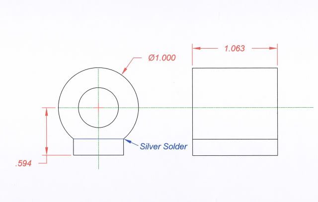
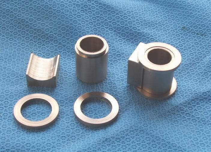
I've never made this combination of a cylinder and block. The material is brass. I'm thinking turn the cylinder, mill a flat on it and silver solder a rectangular block to it. Is this the way, or is there a better way?

I'm also new to silver solder, but have done some trial pieces and have read the threads and still have a couple of questions. I know I have to keep the two pieces from moving and also provide for a small gap between them (prick punch dimples). However, do I "tin" the two faces with silver solder before joining them or is it better to place small bits of solder randomly between them? Alternatively, if I apply solder to the joint from the outside edges will it wick all the way into the middle of the face (I'm a little shaky, so am not particularly thrilled with this approach)?

Any help or advice is greatly appreciated.

Regards,
Dennis
 
Anther way would be to leave the cylinder round and mill out the rectangle to mate up with the cylinder. Two even rows of dimples near the outer edges center punched would separate the pieces evenly. The silver brazing rod could be hammered flat, and 3 - 4 rows laid between the 2 pieces to be brazed. This way the 2 pieces should line up and won't shift when the filler rods melt. Use plenty of flux and clean everything well. Boring out the cylinder first will allow the pieces to heat up faster and more evenly. To braze the pieces the way your illustration shows both pieces could be drilled for 2 line up pins in out of the way locations. dimples used to separate, and brass pins to assure line up, brazing the four pieces together to become one assembly.

-MB
 
The method that I used was as you described, except that I turned the diameter of the cylinder and performed a "pre-bore" while the part was still attached to the brass round I was using. I found that it was a tremendous assist in holding and lining everything up. When I was satisfied with it all, I did a final bore, face off, and cut off. The soldering wasn't that difficult, as I tinned the pieces first and then joined them, this ensured a solid and thorough joint, at least for me it did anyway.

BC1

1.JPG


2.JPG


3.JPG


13.JPG
 
This is how I do 'em.
cylindercomponents.jpg
 
Guys,

This is really helpful...Thank you!

BearCar1...That's exactly the part I need. Could I borrow yours? I'd have it back in about 25 years. ;D Seriously, that's a great looking part and seeing your approach makes me a lot less aprehensive about making it.

MB & Tel...What do you use to make the saddle part?

Kvom...I have a Sherline mill with rotary table, but they're pretty light. I saw the smiley, but is milling it from one piece a practical possibility? I'm curious about how you would go about it.

Thank you again.

Dennis
 
Morning' Denny, Yes, you may borrow my cylinder, but only if I cn come over and play choo choo with your engine when it is finished :big: Man that is one nice looking piece of fabrication, I am so jealous it isn't funny.

Tel: yes, please tell us some more about how you approached making that saddle part, I would be very much interested in hearing of that as well.

Cheers
BC1
 
I saw the smiley, but is milling it from one piece a practical possibility?

If you have a piece of round bar with a radius >= .594, you can mill out the profile of the base using normal cuts. Then mount the piece on the horizontal rotab centered on the bore and mill the round profile (several partial rotations using the end flutes). It would make sense to drill out the bore to aid in clamping to the table, and a tailstock would likely be useful if the piece is long.
 
I sat in on the silver soldering seminar at NAMES this year. Jerry Kieffer gave the presentation. He recommended just fluxing the parts (lots of flux) and clamping them together. Don't try putting the solder between the parts. Cut a small length of solder and lay it on the joint to be soldered. When the solder melts it wicks into the crack between the parts with no problem.

His real trick was how he cleaned the parts after soldering. He used a bead blaster with fine glass beads. This eroded the solder off the parts without touching the base metal (steel was what he used). Left a perfect part with no visible solder joint.

Charlie
 
Here's one I made earlier.....
before silver soldering
walleng2.jpg

cylinder unit set up for valve setting
walleng4.jpg

Mark
 
That 'saddle' on the underside of the port face is simply scooped out with a boring bar. In the good ol' 'pre mill' days I used to do them on a vertical slide on the Myford, but these days I use the boring head on the RF30. In that case - prepare a piece of material a bit longer than 3 port face pieces, set it up truly vertical in the vise with enough showing to do one - clock it in in the usual way, and have at it. Once it's done, flip it over and do t'other end.
 

Latest posts

Back
Top