arnoldb
Well-Known Member
- Joined
- Apr 8, 2009
- Messages
- 1,792
- Reaction score
- 12
I'm going back to the work on Monday, and having had little Tiny do a good stint on holding down papers and being a general conversation piece there, it's time for something new. Fred should do as a good stand-in for a while, but what then ?
Well, having built a couple of rocking engines and wobblers, it's time for something different and to try out my new mill; There is nothing like project work to get to know one's machines.
I had a difficult time choosing between Elmer's Grashopper (#37) and Beam (#24), but with the Grasshopper the slightly larger one (and based on a good friend's suggestion - thanks Mate") ), it is next up.
), it is next up.
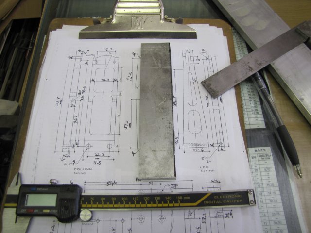
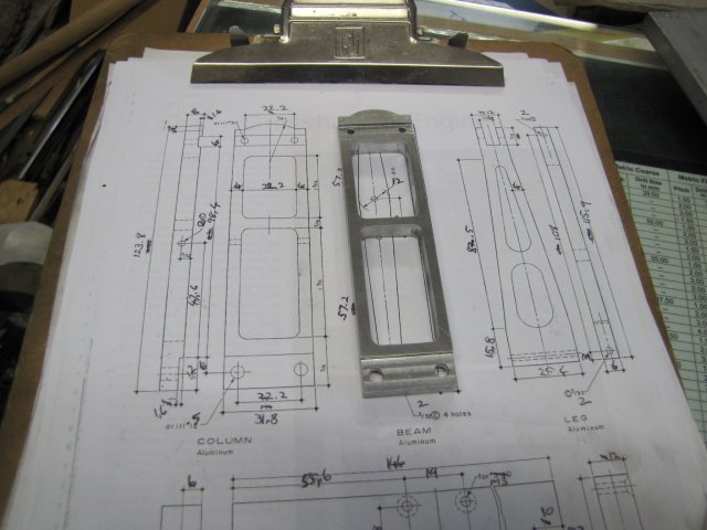
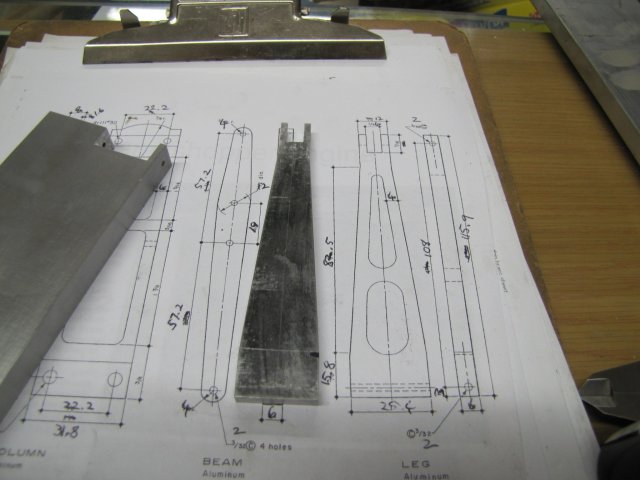
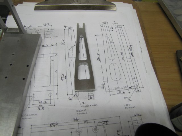
First, I spent a good couple of hours calculating and jotting down metric dimensions & threads on the plans, and also checking what material I had available and compensating/improvising as needed, then it was off to the shop.
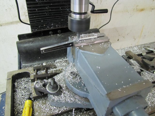
Building started with the base; I sawed a suitable section off of some 12mm Aluminium plate I bought while in SA, and milled the edges to size. I thought I had taken a photo of the stock when I started, but didn't :-[.
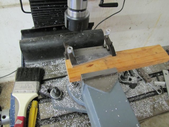
Almost immediately, I was made aware of a painful issue with my mill; there is not enough space between the Z locking lever and the shield safety switch mounting, and my fingers took a couple of painful knocks getting wedged in there while I was concentrating on setting depths and so on, and not looking while operating the lever.:
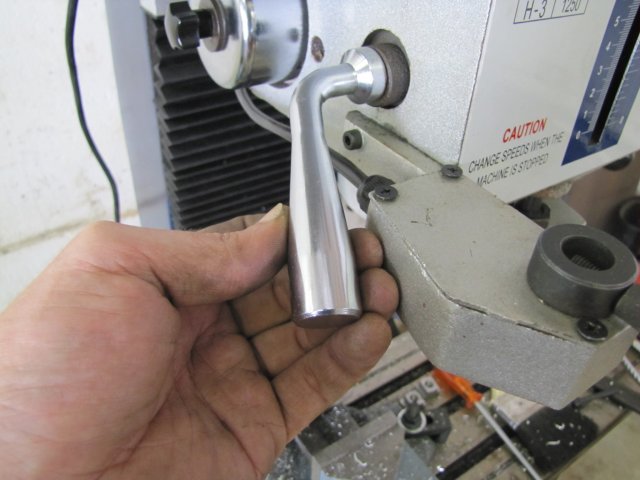
So I spent a couple of minutes removing the mounting, and bypassing the safety switch in the mill's wiring cabinet. I'm fully aware of the safety implications just in case anybody is wondering. Sometimes H&S gets so obnoxious that it is a safety risk on it's own. I'll use the holes left on the mill to mount a light in a sane fashion; that will compensate a bit
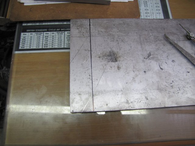
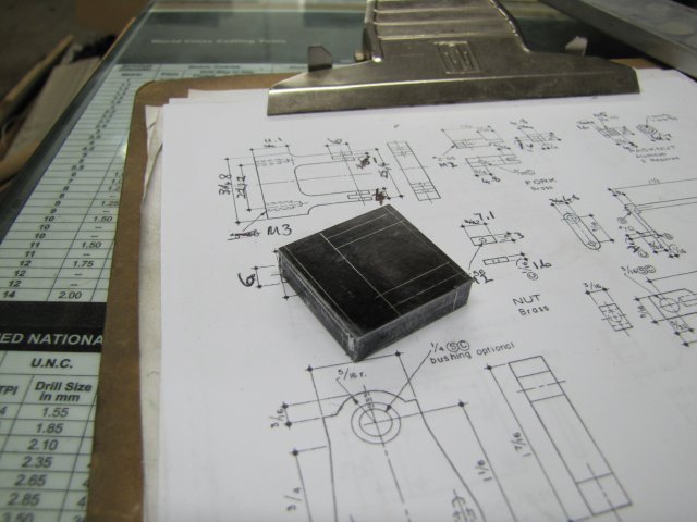
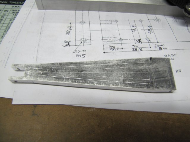
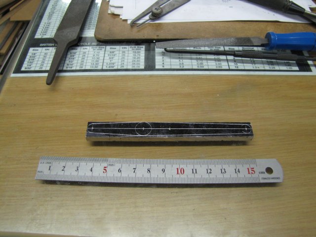
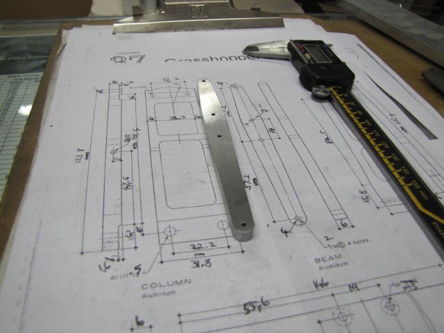
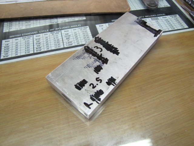
Having milled the base down to size, I did the layout. Permanent marker run across approximate locations and then lightly layed out the dimensions, and punched for the holes. The numbers are the metric drill sizes I need for the surrounding holes:
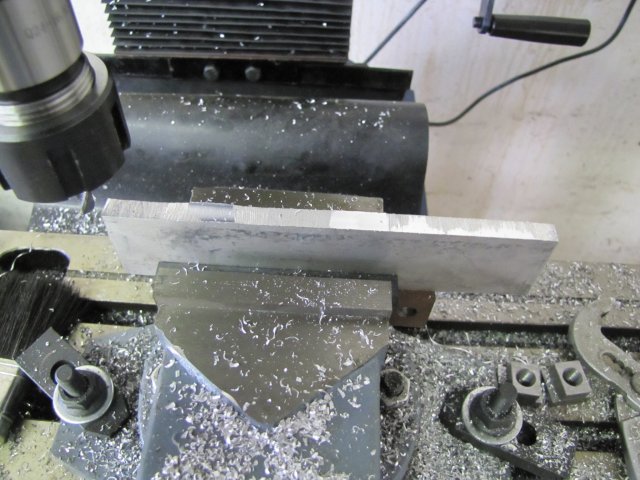
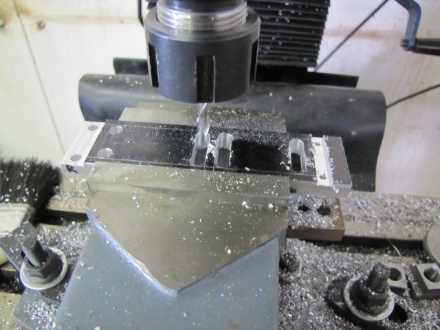
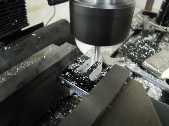
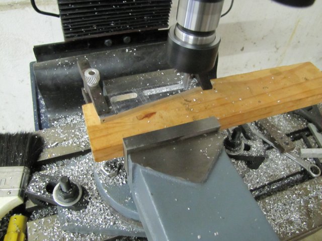
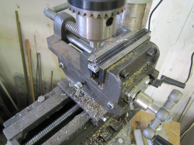
Milled the mounting slot for the leg. Decided to test out the machine's dials, so found the edge, zeroed the dial and cranked in 3mm from the end. Hmmm, not enough you idiot; you need to add the cutter's size as well... Fortunately a 9mm cutter, so three more full turns and spot on. I'll need an edge finder soon; for now, I used some paper with a known thickness like Tel mentioned in one of his posts - works a treat. Fortunately, I remembered to deduct the cutter's width for the other side of the slot; hit things spot on and literally split the mark-out lines:
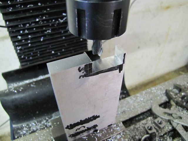
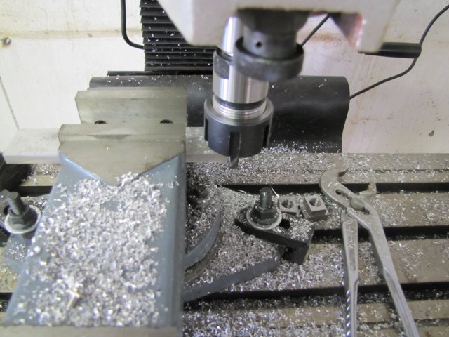
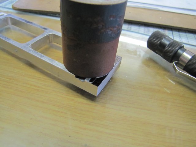
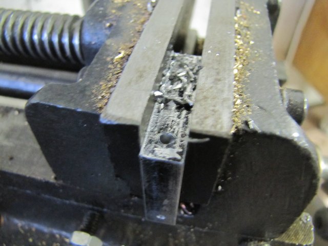
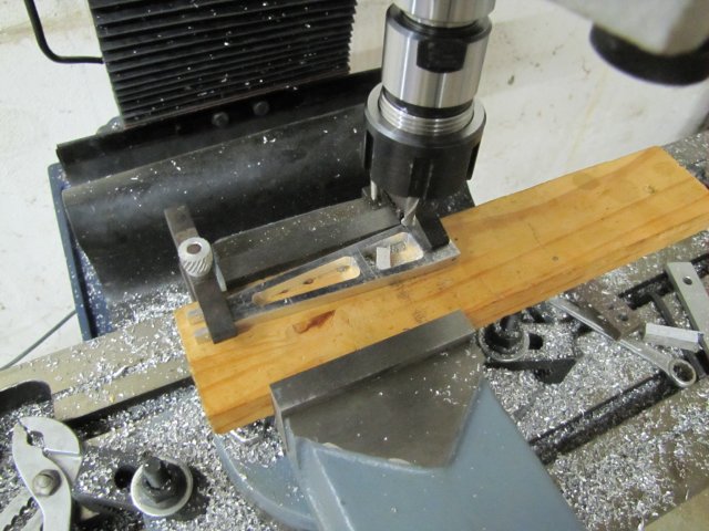
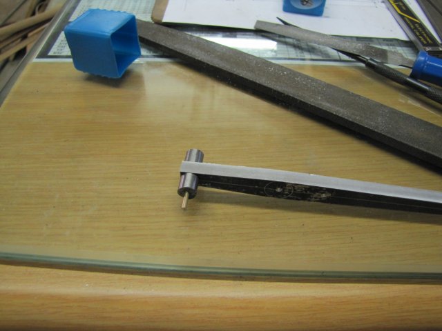
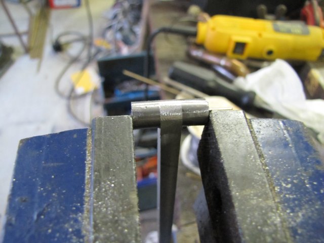
The mill's chuck cannot take drills smaller than 3mm, so off to the drill press for the next steps; I took a chance on drilling the the 2mm holes for the leg pivot pin like this; fortunately the drill didn't wander and the bottom hole was spot on. There was only about 6mm of the drill gripped in the chuck to get the needed depth, and end of the spiral is well below the top hole:

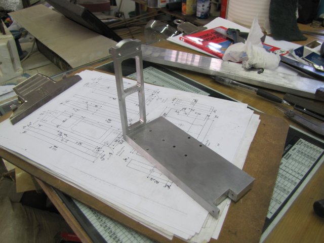
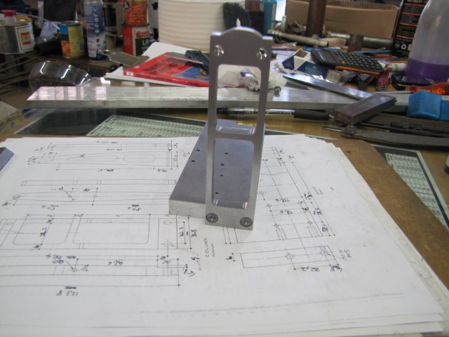
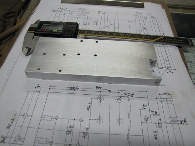
Then some tapping followed - all 2.5mm holes were tapped out to M3, and the 3mm holes were countersunk at the bottom of the base. So that completes the base machining-wise:
Hopefully I can get some more parts done tomorrow; this build may take a while to finish.
Regards, Arnold
Well, having built a couple of rocking engines and wobblers, it's time for something different and to try out my new mill; There is nothing like project work to get to know one's machines.
I had a difficult time choosing between Elmer's Grashopper (#37) and Beam (#24), but with the Grasshopper the slightly larger one (and based on a good friend's suggestion - thanks Mate
), it is next up.First, I spent a good couple of hours calculating and jotting down metric dimensions & threads on the plans, and also checking what material I had available and compensating/improvising as needed, then it was off to the shop.
Building started with the base; I sawed a suitable section off of some 12mm Aluminium plate I bought while in SA, and milled the edges to size. I thought I had taken a photo of the stock when I started, but didn't :-[.
Almost immediately, I was made aware of a painful issue with my mill; there is not enough space between the Z locking lever and the shield safety switch mounting, and my fingers took a couple of painful knocks getting wedged in there while I was concentrating on setting depths and so on, and not looking while operating the lever.:
So I spent a couple of minutes removing the mounting, and bypassing the safety switch in the mill's wiring cabinet. I'm fully aware of the safety implications just in case anybody is wondering. Sometimes H&S gets so obnoxious that it is a safety risk on it's own. I'll use the holes left on the mill to mount a light in a sane fashion; that will compensate a bit
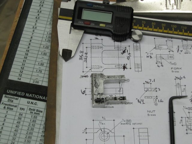
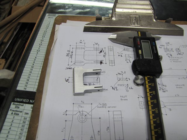
Having milled the base down to size, I did the layout. Permanent marker run across approximate locations and then lightly layed out the dimensions, and punched for the holes. The numbers are the metric drill sizes I need for the surrounding holes:
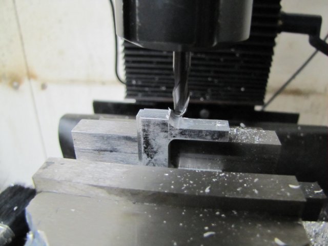
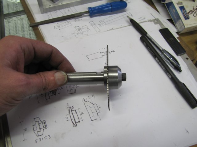
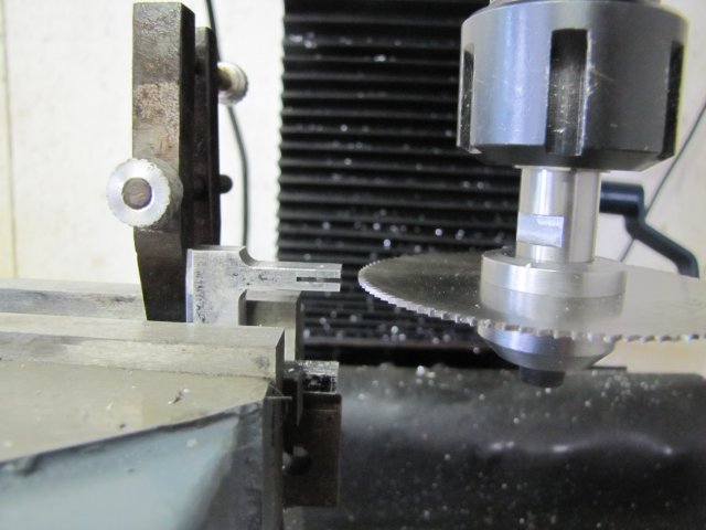
Milled the mounting slot for the leg. Decided to test out the machine's dials, so found the edge, zeroed the dial and cranked in 3mm from the end. Hmmm, not enough you idiot; you need to add the cutter's size as well... Fortunately a 9mm cutter, so three more full turns and spot on. I'll need an edge finder soon; for now, I used some paper with a known thickness like Tel mentioned in one of his posts - works a treat. Fortunately, I remembered to deduct the cutter's width for the other side of the slot; hit things spot on and literally split the mark-out lines:
The mill's chuck cannot take drills smaller than 3mm, so off to the drill press for the next steps; I took a chance on drilling the the 2mm holes for the leg pivot pin like this; fortunately the drill didn't wander and the bottom hole was spot on. There was only about 6mm of the drill gripped in the chuck to get the needed depth, and end of the spiral is well below the top hole:
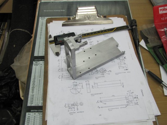
Then some tapping followed - all 2.5mm holes were tapped out to M3, and the 3mm holes were countersunk at the bottom of the base. So that completes the base machining-wise:
Hopefully I can get some more parts done tomorrow; this build may take a while to finish.
Regards, Arnold