Another X2 Mod thread

Home Model Engine Machinist Forum

Help Support Home Model Engine Machinist Forum:

This site may earn a commission from merchant affiliate links, including eBay, Amazon, and others.
Time for another update...

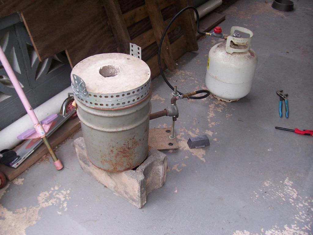
The counter-weight is done, I setup my old casting furnace and put it to use as you can see here..


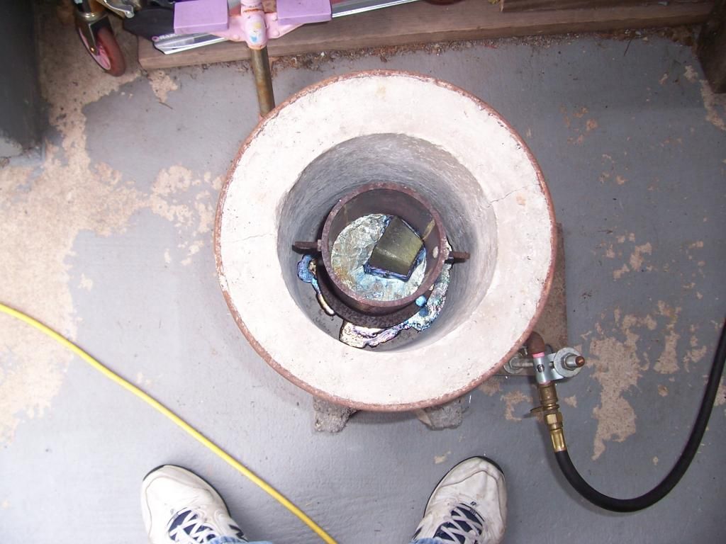
A view inside the furnace after it cooled.


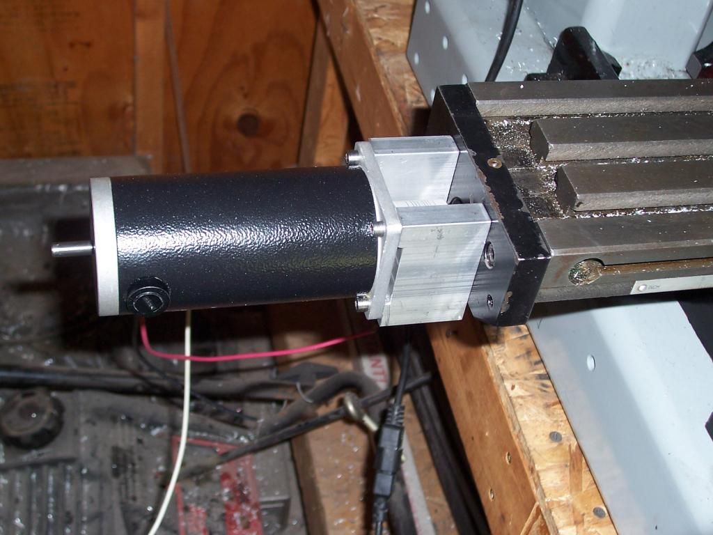
Next up was a mount for the x-axis motor, the first job was to drill four counter-bored holes to accept some SHCS in the table x-axis end plate. These screws will hold the motor mount blocks.


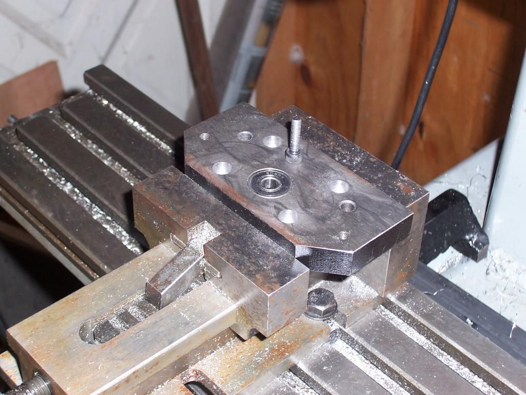
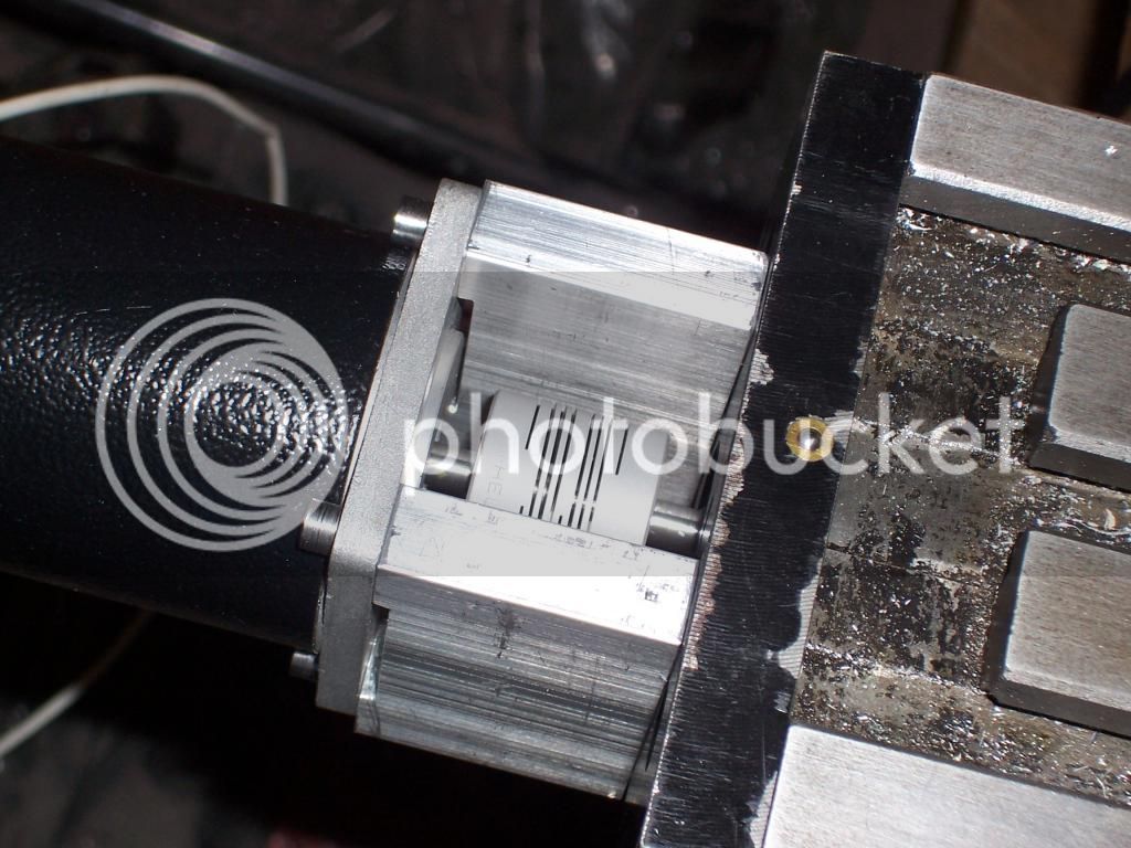
Here's a couple of photos showing the arrangement of the end-plate, the motor mounts and coupling.


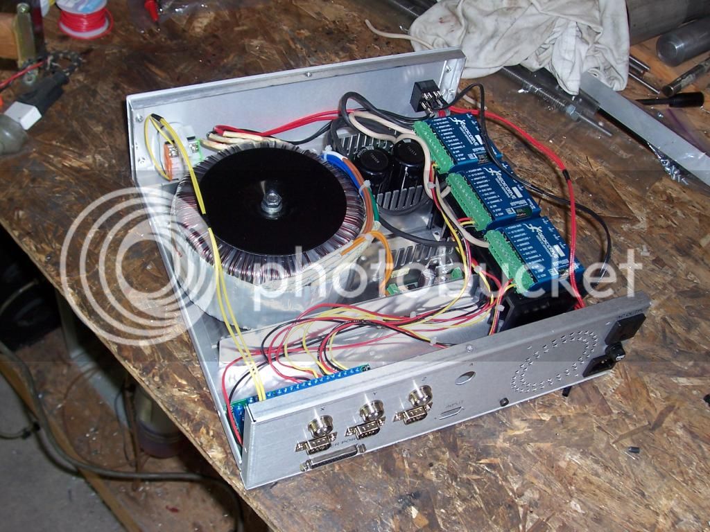
I decided to take a break from making parts and assemble the control box. Here's a work in progress pic of installing the internal wiring.


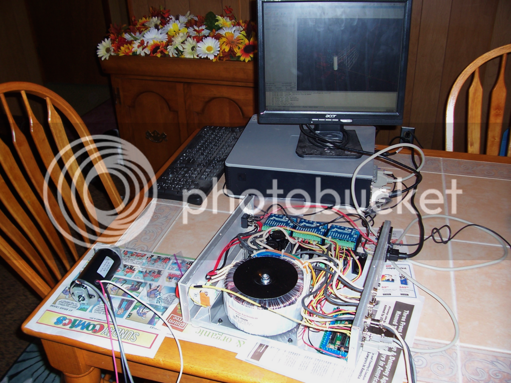
And a photo of testing the control box with Linuxcnc, all axes tested out ok which was a relief.


All that is left to do is make the Z-axis nut and fit the Y-axis handle with a toothed drive pulley, hopefully I'll get those done by next weekend as I'm looking forward to making some chips. ;D

Thanks for reading.

Steve.
 
Final update.

The z-axis nut is done, it was made from some round bar stock and .5" plate. Here's a shot of it after completion.


The last job was fit a 30 tooth pulley to the y-axis hand wheel.


Then it was just a matter of assembling all the bits.

The z-axis completed..


A shot of the assembled mill with the control unit.


This completes the build, I have spent most of the weekend getting to know the software, jogging axes to and fro and grining like a schoolboy :D

At some point in the future when all the wiring has been tidied up I will fill the steel tubes with an epoxy granite/concrete mix to add some damping.

Thanks for reading.

Steve.
 
Postscript update..

Here's a clip of the mill cutting an airfoil profile which is intended to be the top half of a compressor blade. This is just a test, but I was pleased with the result.

[ame]https://www.youtube.com/watch?v=fBVByTEIfXM[/ame]

And a pic of the completed test piece.


Thanks for reading.

Steve.
 
Last edited:
The main post is 36" x 4" x 6", the two outside base pieces are 4" x 3" x 24" and the inner base piece is 4" x 3" x 18", all pieces have a wall thickness of .350-.375"

Regards.

Steve.

Excuse me , what is the method of connecting a main pillar and two side base pieces?
Did you use welding or bolting?

Thanks
 
Thanks, but I see some holes outside of base piece. I think it is first fixed by screws, and then weld together. Is that so?
Sorry for my google english.
 
Hi Steve, apologies if I missed it in an earlier post, just wondering what servo's are you using?
They look plenty capable in the video, nice work.
 
Hi Guys, thanks for the interest.

expertdb,

The pillar and column are bolted and welded together, initially I wasn't going to weld it but I decided to add a few beads as extra insurance against crashes.

///,

The servos are 350oz inch units from Automation Tech Inc.
Here's a link.. http://www.automationtechnologiesinc.com/products-page/nema23-m-dc-servo-motor

They work very well, I'm not close to using them at full capacity yet. I have a lot to learn when it comes to cnc so I'm taking it slowly.

Regards.

Steve.
 
Thanks for your answer.

And my last question (maybe :)). How many bolts you used for rigid connection of main pillar and original column of mill?
 
There are 8 bolts holding the column to the main pillar. You can see the holes in this photo.


There are 4 steel plates 1" * 1/4" * 6" (6mm * 25mm * 150mm) long that are drilled and tapped with two holes that are inside the original column to clamp the column to the pillar. I also drilled the rear of the pillar with the same bolt pattern so I could get a long allen wrench to reach the bolt heads.

I hope that is clear ;)

If you watch the video, you can see the bottom ends of the clamp plates protruding from the column

Regards.

Steve.
 
Last edited:
One more update ...

While I've been pretty happy with the performance of the mill in general and have enjoyed using it with the CNC conversion, one last thing to be addressed is the vibration damping of the new base and column. During heavier cuts there can be a lot of resonance noise which can sound pretty bad at times.

The last ( I hope ) mod to the column and base was to fill them with epoxy granite/concrete. This will hopefully provide the vibration absorption with some more mass and rigidity that the mill needs. Another reason for this mod is I want to try some carbide tooling in some nickel alloys and I don't want to chip the tooling from excessive vibration.

Here are pics of the top of the column filled with epoxy granite, also visible are the clamping plates used to hold the Z ways to the column.


In case anyone is wondering, there are tubes embedded in the epoxy granite to allow access to the lower bolts holding the Z axis ways. This will allow for dis-assembly or loosening for tramming.

Thanks for reading.

Steve.
 
... was to fill them with epoxy granite/concrete. This will hopefully provide the vibration absorption with some more mass and rigidity... Steve.

That's interesting. I've heard of people doing this on CNC router frames with good results. Keep us informed how it performs. When you say 'granite/concrete', what exactly is the aggregate medium? (granite chips, quartz sand, a mixture?). Also curious what kind of epoxy resin you used.
 
Hi Peter, thanks for your reply.

When you say 'granite/concrete', what exactly is the aggregate medium? (granite chips, quartz sand, a mixture?). Also curious what kind of epoxy resin you used.
I based my mix on the mixture at the cnccookbook site. Instead of using 62% gravel 23% sand 14% epoxy, I used an 80lb bag of Quikrete, my reasoning is that it has sand and gravel in similar proportions plus it has finer material in the form of cement powder to further fill in the gaps. I used 6 parts of Quikrete to 1 part of epoxy by volume. The epoxy I used was West System 105 resin with 206 hardener. I used the slower hardener as ambient temps in the shop were about 80-90 degrees f.

Regards,

Steve.
 
Last edited:
That's interesting. I've heard of people doing this on CNC router frames with good results. Keep us informed how it performs.
I spent the day making an adapter to mount a dial indicator to the ways of my lathe, this gave me my first real test of the mill since the epoxy granite fill. All I can say is, wow! what a difference, the vibration absorption has radically improved. Any moderately heavy cut previously would result in lots of noise presumably amplified by the hollow steel tubular members of the frame, now there is barely any. I tested heavier cuts until the slop in the dovetails of the table became a factor.

At this point I think the new frame is a success, but it has revealed that the fit and finish of the ways are below par and need to be addressed.

Regards,

Steve.
 

Latest posts

Back
Top