A new attempt at making piston rings

Home Model Engine Machinist Forum

Help Support Home Model Engine Machinist Forum:

This site may earn a commission from merchant affiliate links, including eBay, Amazon, and others.
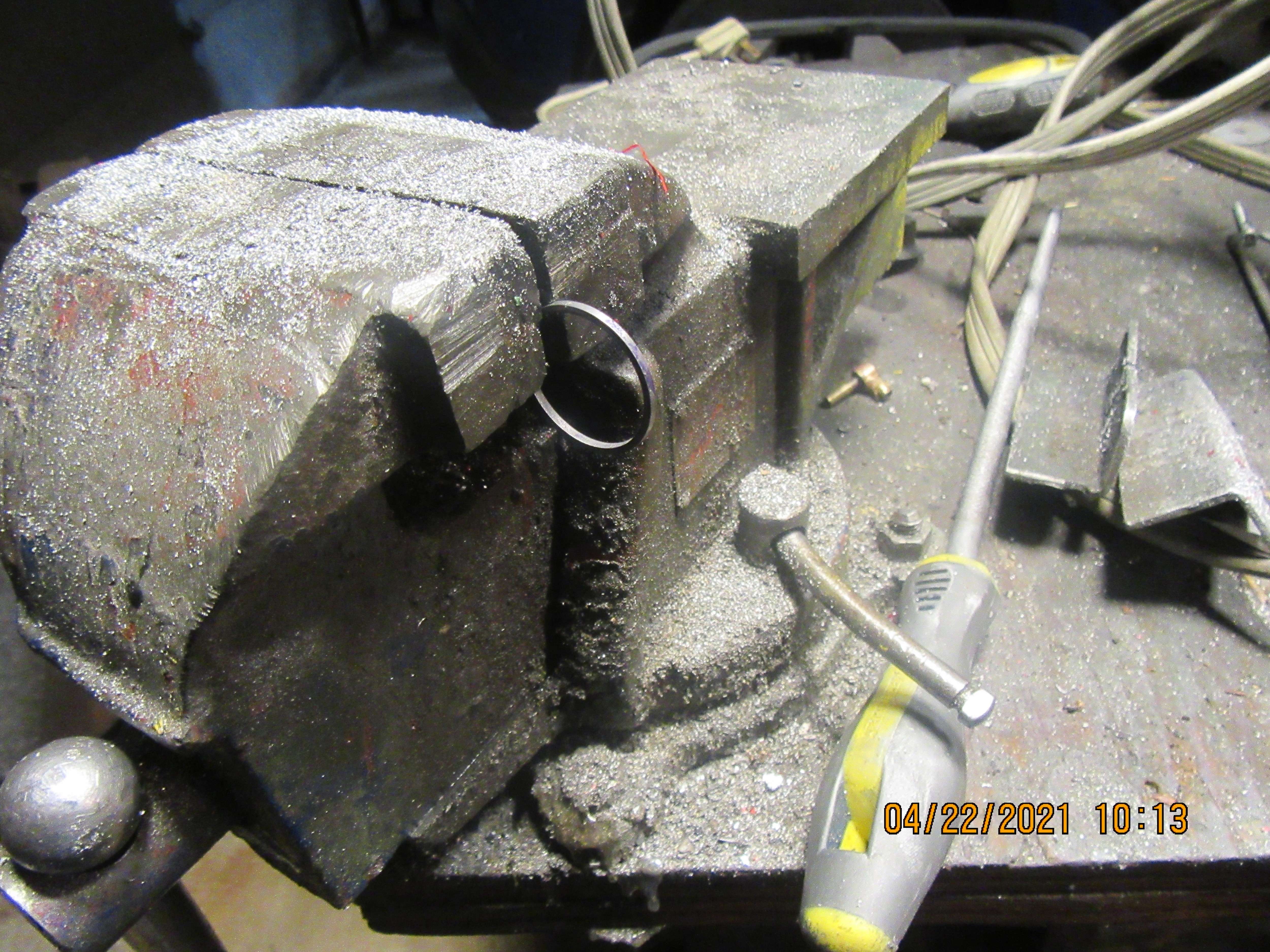
I started making rings with the Chaddock method. A real pain, extra fixtures and much scaling.
Following the advise of an old fellow I met at Cabin Fever I tried his technique.
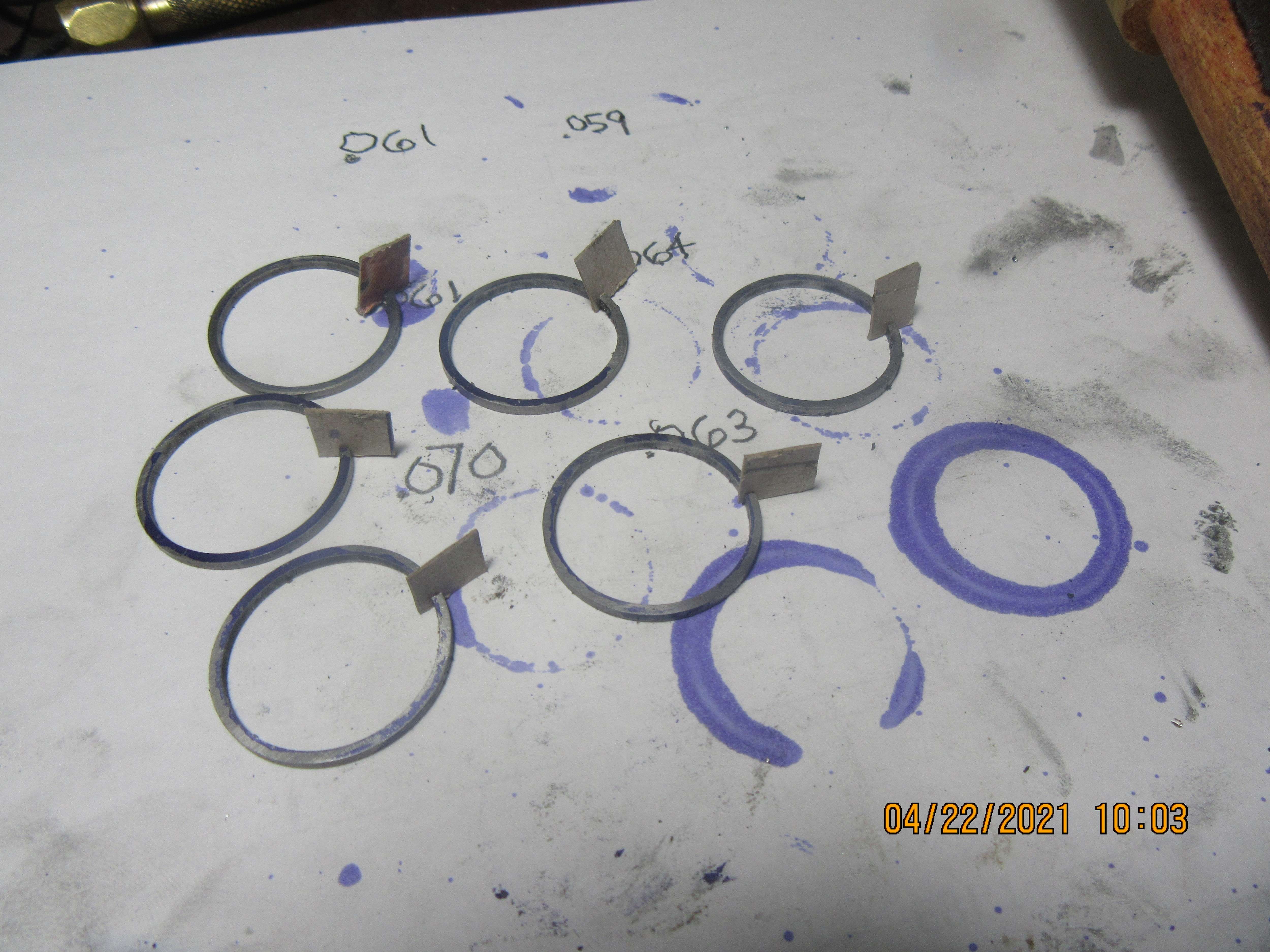
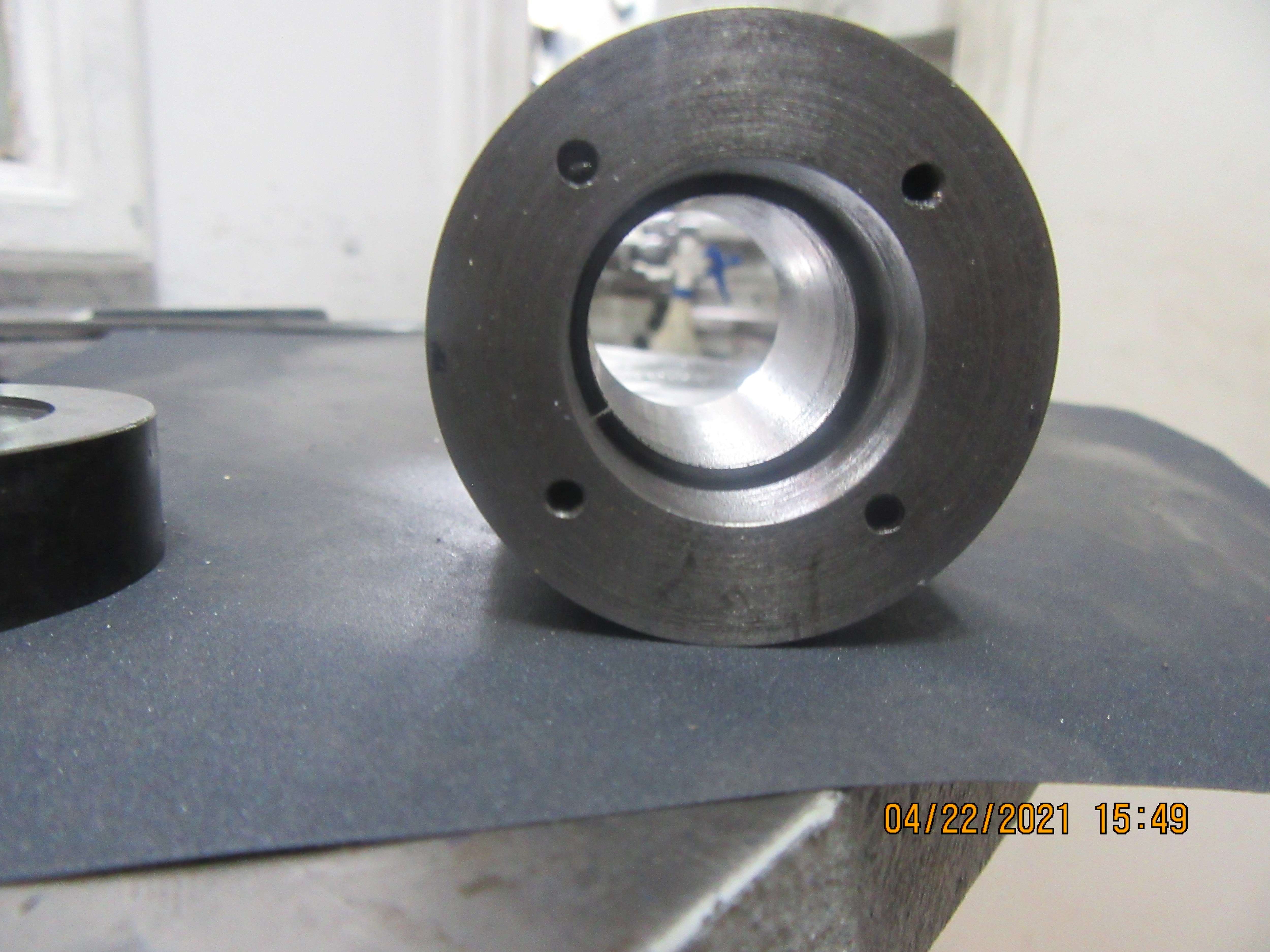
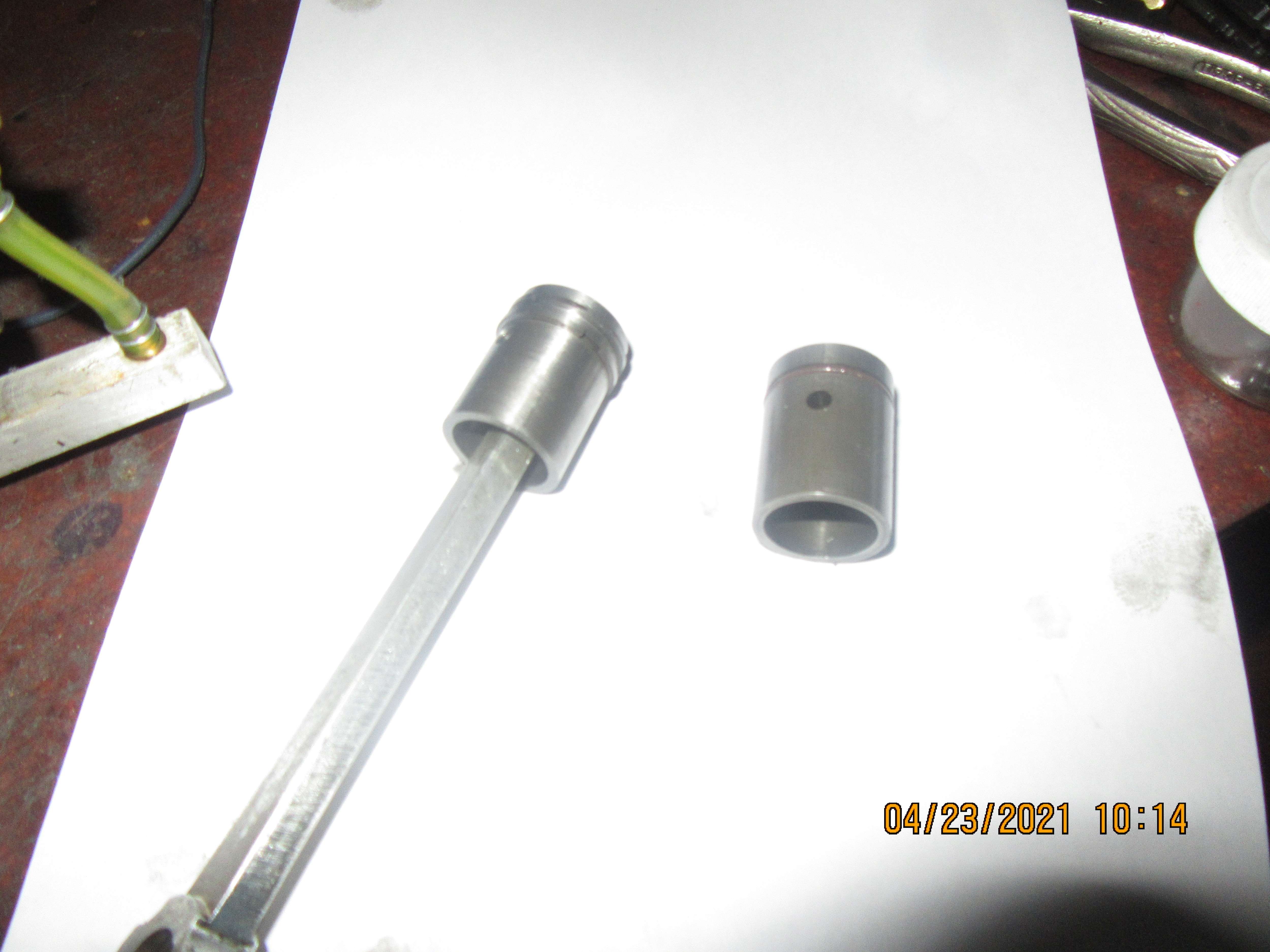
Next engine I machined the ring tube to a Diameter = Bore + OpenGap/pie
After slicing the ring I milled out the OpenGap + The Working Gap
My ring now has a "lenght" = Bore x Pie - Working Gap
It springs inside the bore to fit "just right".
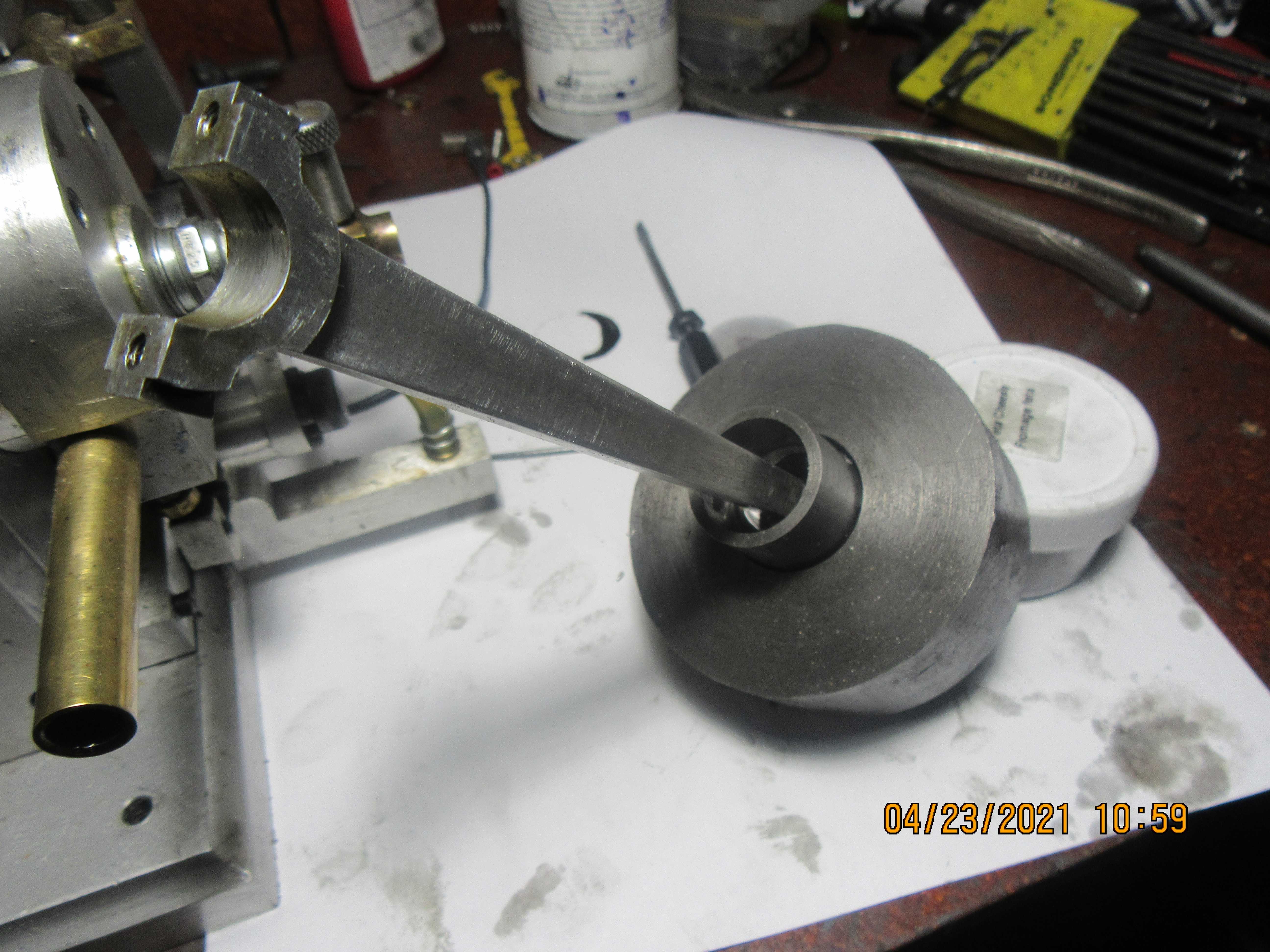
If one goes to the excruciating math to calculate the shape of a gapped ring that becomes circular under under uniform radial pressure, he will find out the ring I made is all wrong.
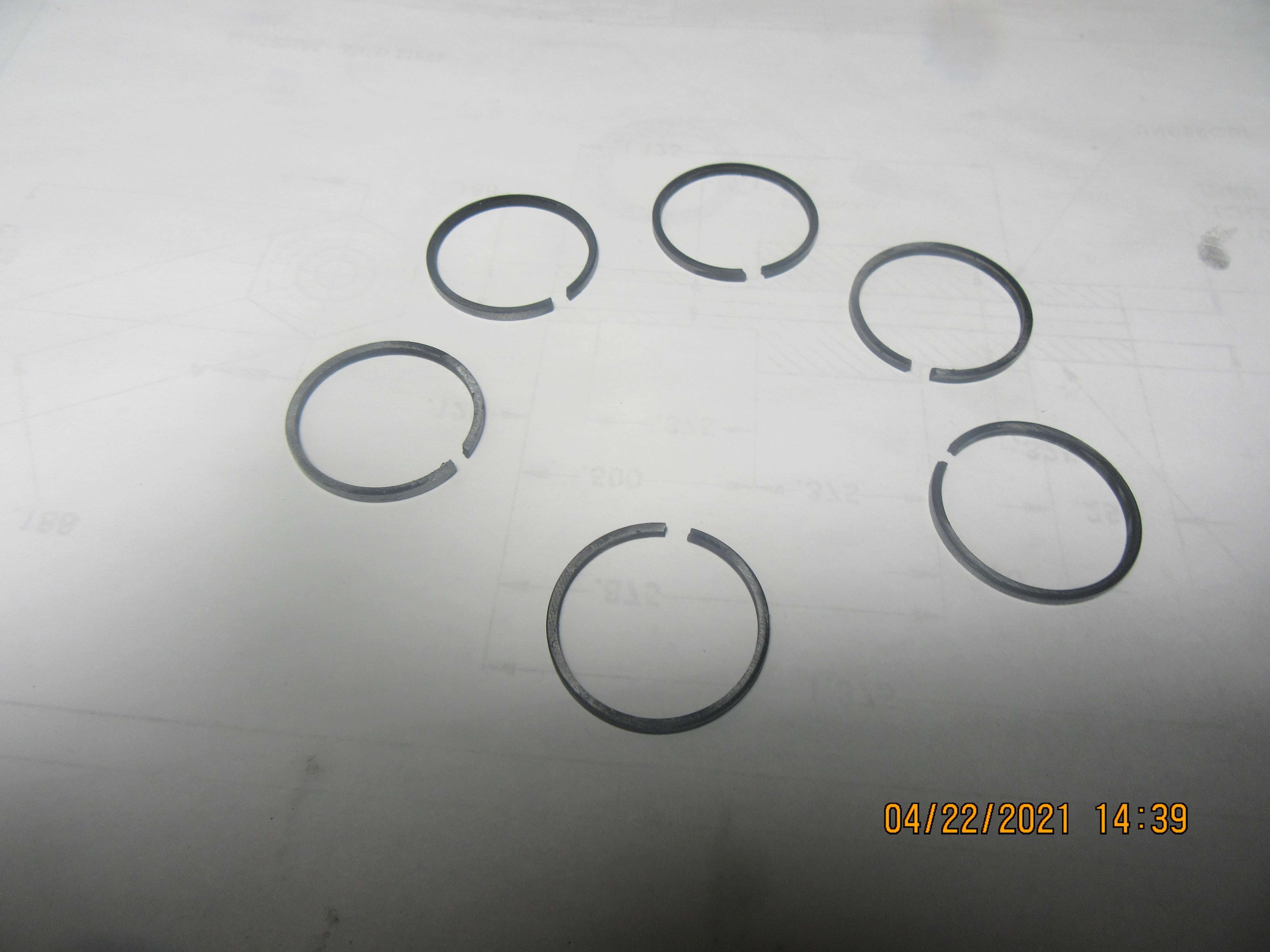
After running 1/2 an hour inside the engine the ring show axial wear marks all around indicating all of its periphery touches the cylinder. Compression is good and the engine runs well.
 
The rings have all been split. This is a very simple procedure where part of the ring is clamped in the vice and one half sticks out the end of the vice where it can be grabbed by my finger and them and gently pushed back and forth until it cracks. You have to be careful with your pushing and pulling, as you don't want to snap the ring in two pieces. At this point in the game, the rings are still the same i.d. and o.d. as they were when machined.
dwdHtB.jpg

Yu8ZKA.jpg
 
Depending how thick (wide ?) your rings are it's probably less risky to lay the ring on the table with a piece of wire under a section of the circumference. Wire maybe #22 or so. Then put a thumb on either side of the wire and press down hard. it'll snap right over the wire. Also it helps to score the ring where you want it to break. If you have heavy duty rings this doesn't work very well as it's hard on the thumbs. But it works in most cases.

Using the vise I wouldn't bend the ring back and forth attempting to break it. I think you'd stress the material.

If you get into making a lot of rings consider making the cleaving (cutting) tool George Britnell showed in another thread here. It's actually a copy of the one detailed in (I think) the George Trimble full article. I recently made one after having trouble using my wire method on some beefy rings. It works very well and gives a controlled perfect break right where you want it.
 
Last edited:
I have made a heat treat fixture on which to mount the rings. Trial and error showed me that making the inside diameter of the fixture 0.942" diameter and forcing the rings over it resulted in a 1/8" gap between the ends of the ring. I truly felt that if I spread the rings any wider they were going to break. The rings are tightly compressed between the two discs to keep the broken ends of the rings perfectly in line. The back-side of the fixture has been hollowed out so it will have less mass to heat up. I will heat fixture and rings to a cherry red with my oxy acetylene torch, being sure not to let the torch flame play directly on the rings. The ring ends will be filed after the heat treat is finished and the rings demounted.
iARJ6K.jpg
 
Such is the nature of messages on forums. People don't get to comment until it's possibly to late.
I hope you didn't heat the rings too much. This was one of the controversial issues with the Trimble article.
Many thought that he heated the rings far too hot.
The correct temperature - it has been decided - is DARK CHERRY red.
That means that in subdued light (almost dark) you just barely see the fixture beginning to turn a red colour.
A propane torch would be plenty to save from going too far.
Then you hold it there for a few minutes (depending on mass) and let it cool slowly.
I hope you didn't heat them too much.
I think the pitfall is that the cast iron metallurgy will be affected. Not sure how.

A side effect of heating them too much is they develop a scale on the outside. If properly heated they come out darkened but with no scale.

How were your results.
 
After being heated cherry red, and left to air cool, then a little bit of clean-up, the rings have all taken a new "set" and the gaps remain open about 1/8" after they are removed from the fixture. I have seen on Youtube where some people heat the rings to cherry red, then drop them into a bucket of oil or water while they are still cherry red. I have no idea why they do that, and I've never read anything saying that this is a part of the process. My next step will be to square up the broken ends and test fit them into a cylinder to check that I have about 0.004" gap between the ring ends.
ZspxFc.jpg
 
Looking good.
Terry Mayhugh described a light mask you can make from a plug of plastic or anything really that you put in place in the inside hole of the ring when it's in the cylinder. It has lip on it that stops it from dropping through that is just shy of the cylinder diameter. Once in place you can shine a bright light behind it and look down the cylinder for light passing between the ring and the cylinder wall. The mask blocks all the light from passing through the center leaving only that leaking around the ring. If you move it around you should not see any spots of light between the ring and the cylinder You can decide if you've succeeded or failed. Terry said he has a few failures out of a group of ten rings or so. He only accepts those with no light leakage.
He described this process with pictures elsewhere recently. Worth a look.
Give it a try.
 
The six rings are finished and properly gapped to 0.004" when installed squarely into the cylinder. As far as I can tell, I've made six good rings.---A funny thing about cast iron---it grows when it's heated, and when it cools off, it doesn't return to the dimension it was before. It is always a bit larger, even after it cools down. I knew about this from a previous experiment and I know that the two stroke airplane engine crowd will sometimes heat up a piston to "grow it a little" if they aren't running tight enough to get good compression. It shows up here because after these rings were split they would still fit down into the 1" cylinder bore perfectly. After being heat treated, before having the ring gap filed, they would no longer fit into the cylinder. I expected that, but it's still kind of surprising.
UZf2wj.jpg
 
This is the side shaft hit and miss engine that I will be trying these rings on. It runs like a charm with the single Viton ring on the piston. I'll know after I make a new piston and put a couple of these new rings on it how successful I was at ring making.
 
G'Day again Brian, et al.

I seem to remember an article, I think it was Tom Walshaw in Model Engineer (happy to stand corrected), about piston ring and their wall pressure for various cyclinders. Went something like Steam - 6 to 8 PSI, Petrol - 16 to 18 PSI and Diesel - 38 to 40 PSI. Dealt with cylinder pressure/compression ratios etc. It also gave ratios for ring dimensions to bore/stroke etc. Someone clueyer than I might have the article, a reference or a clever search engine.

I've also viewed Mr Crispins' Youtube articles on Piston Rings and thought the dimensions were a little excessive. (Good entertainment, that bloke.)

I was so impressed with Terry Mayhughs' recent article on Piston Rings that I printed it off for future reference. (Straight to the library it went.) Would like to get the copies from SIC magazine with the full written "Trimble" article when the exchange rate is more favourable. George Britnells' articles are also a very valuable reference source (printed and in the binder already).

Kind Regards,
Stay safe,
Don't be good,

Trevor,
Melbourne, AU.
 
Trimble's method has science behind it and relies on the use of a specific set of dimensions for the rings and the fixture used to heat treat them. Here's a photo that I posted in one of my builds that contains a summary of those dimensions. Before giving up on an another approximate scheme that may not work, give it a try. The dimensions of the heat treatment fixture are just as important as the ring dimensions. - Terry

792FFB03-7CFF-481D-AF4E-F3A9D163BAA0.png
 
Last edited:
Hi Brian, i do not have any expert advise to offer but i will respectfully throw in my experience on ring making which alot came from other members.

first attempt. perlitic gray fine grain continuous cast cast iron was recomended. i used what was advertised as this and heated and cut the rings like you have i found that they would break on install. yes i have used store bought rings and the had much more spring to them than the ones i made.

i then found some scrap old cast iron. did some test cuts and the grain seemed to be better and darker. (especially compared to window sash weights - do not even try those) it was a part to an old stoker coal furnace i finallly learned. it cut much the same as the store bought cast iron but the powder left was much darker and if rubbed between fingers i could actually feel a slight difference betweeen the 2. just a guess its more graphite in the scrap iron? that said after emory cleanup, spliting, heating and a final cleanup the scrap was so much better than the store bought.

oh, and on splitting. i was using the vice and a machinist clamp with a little tweak to split them until another member suggested to use some wire side cutters. aka wire cutters. worked great and didnt leave the dent or angle like if cutting a piece of copper wire. it just "popped" the split in the ring without making an angled dent or cut mark on them. which also didnt tweak them / warp them which is easily done using the vice / clamp to tweak enouhg to split it.


now all that said i kept making rings until it finally worked, i am really happy you are experimenting and posting a write up on it so hopefully i / others can follow and make them easier.

thank you for showing us.
 
I am always amazed at the ring making methods we use. It seems that one person uses all sorts of crude methods and the rings work just fine. The next person holds tolerances to .0001 and the rings will not work.

For what it is worth, the last set of rings I made I heated them to 1100° for an hour in my old ceramic kiln and then left them to cool in the kiln overnight and they seem to be working fine. I had made some ring prior to that for the same engine and heated them just to 1100° and shut off the kiln and that set did not work. Others seem to have success with placing the rings on a brick and heating them with a torch. Skill or dumb luck?
 
This is the new cast iron rings mounted on the new cast iron piston. The old piston with Viton ring is setting beside it. No real drama. Lots of lubricating oil and a bit of breath holding, and the new rings went into place without threatening to break as they were being installed. Next test will be to see if new piston with rings will fit into a 1" reamed cylinder.
ADAUa4.jpg
 
This was the last test prior to putting the piston back into the engine. I had to absolutely convince myself that the new piston and rings would indeed pass thru a 1.000" diameter hole. If not, that's a good way to break rings or bugger up the end of the cylinder. It did show that the cylinder needs about a 20 degree overall tapered lead-in to compress the rings as the piston enters, but once in there it slides along nicely without any scraping or gouging. The hit and miss engine this is going back into doesn't have a lead machined into the cylinder, so it might get interesting. I am not going to disassemble the engine to machine a tapered lead into the cylinder, so I will have to create some kind of ring compressor to get the piston back into the engine.--Maybe a hose clamp?
iAsWaT.jpg
 
Hasting Piston ring company sells Rings any size, any diameter, any thickness, any type, any design, $3 per set of 3 rings plus postage.

They do not sell by engine cereal numbers. I rebuild a 65HP Mercury outboard engine NO boat dealer could give me rings without the correct cereal number, Hasting sold me 4 sets of rings, $9 total plus $4 postage.

I had 6 used lawn mowers rings at lawn mower shops was $135 but Hasting sold me 6 sets of rings, $12 plus $4 postage.
 
Make a sleeve about 1" long with 1" bore and a taper on one end. Push the piston into the sleeve from the tapered end and then place the 1" end over the engine bore.
 
... I will have to create some kind of ring compressor to get the piston back into the engine.--Maybe a hose clamp?

If that thing you've built is open on the other end and will fit -- it's your spring compressor. I've been watching engine rebuild videos on YouTube, and that's the fancy way to do it. The less-fancy way is a dedicated adjustable ring compressor. When hose clamps are mentioned, it's in the context of "don't do that, it'll just break rings.

You probably do want a slight chamfer on the very end of your cylinder, but only enough so that any slight mismatch between your slip-fit piston and the bore can't cause the edge to catch a ring. And if the assembly doesn't just push in -- don't force it.
 

Latest posts

Back
Top