A different opposed piston engine---

Home Model Engine Machinist Forum

Help Support Home Model Engine Machinist Forum:

This site may earn a commission from merchant affiliate links, including eBay, Amazon, and others.
Baron J---Glad you like it. Chrome is wayyyyyy out of my price range.---Brian

Mmm. There is a guy quite close to me that does chrome plating. I asked him what it would cost to plate the parts based on a picture. He said that it was so little that it would cost more for the time spent wiring the parts up than the actual plating. He said bright nickle would be slightly less costly but even then the actual plating would only be pennies. I also discovered that there is soft and hard chrome also the parts would be acid bathed first and then copper plated and then chromed.

Not a lot of help I know but at least you have some idea of what it would cost here.
 
Hi Brian,

Fantastic engine. Trying very hard not to get tempted to build this engine. That Gus cannot resist building this engine.
Jan 15 .Took the first cut on the milling machine. Christmas/New Year Break over and back to
work. M.I.C. Carbide milling cutters are junks. Will try out the M.I.India cutters.

Jan 17 will test run your H&M with the h&m device. Need to buy some petrol.
How is the weather??
 
Hi Gus--We have just had a week of above freezing weather--got up to +9C one day with rain. This is a pretty traditional "January thaw" and happens most winters. We still have lots of snow on the ground, but it is compacted now. Weather is starting to cool down again now, back into deep freeze for rest of winter. Most animals in the forest (except deer) depend on this thaw, because when the temps. drop back down below freezing all of the compacted snow will freeze and make it much easier for animals to get around, because they can walk on top of the snow. I am totally ignorant of what kind of winter weather you get in Singapore. I am interested t know how your hit and miss system works.--A gentleman over on "Modelenginemaker" forum, from New Mexico, USA has started to build this new opposed piston engine in 1/2 scale, based on my drawings.---Brian
 
Second valve is now finished. Second valve went much faster than first valve. Only had to shut lathe off and check size half as many times. I must get bolder as I work longer. Last week I ordered new lapping compound from McMaster Carr. I got 2 ounce jars of 350 grit, 400 grit, and 600 grit. My previous lapping compound, which some kind soul in USA sent me 5 years ago is finally all used up. I got a surprise. The stuff I have been using for 5 years was dark grey and very oily. The new stuff I got from McMaster Carr is "off white" and has more of a "paste wax" consistency. I now believe that what I previously had was carborundum compound, while this new stuff is aluminum oxide. However, I lapped both valves and valve cages with it and it seems to work just as good as what I had before.
 
As all small engine builders know, there is more than one way to skin a cat!! I didn't like the idea that I had to install the valve in the valve cage and then Loctite the valve cage into place, leaving me unable to ever get the valve out, and making it necessary to drill the port holes into the valve cage while the valve was setting in it. Just too much bad juju there. I lay in bed thinking last night and suddenly had an epiphany!! If I set the center block up on in the mill vice and picked up on the 0.406 diameter holes which the valve cages fit into, then I could use a 5/16" drill and drill right on through the far side of the center block and tap it for a 3/8"-16 thread. The 5/16 diameter root drill hole for a 3/8" thread is about .003 oversize This gives me a hole to put the valve in through after the cages are Loctited and ported. Then I can take a couple of 3/8-16 set screws, coat them with red hi-temp Loctite and plug up the tapped holes.
 
There is a lot going on here folks!! The valve cages are installed and Loctited into place, and you can see the 3/8"-16 set screws that I have used for plugs where I drilled completely through the other side of the main center block, which enables me to remove and/or reinstall the valves after the valve cages are Loctited in place. When I get to the final stages of setting up the engine and testing for compression, I will Loctite those 3/8" set screws into place. The springs and keepers are installed on the valves, (but just for the sake of picture taking). Those are the correct springs, but I will probably have to adjust the length of them. The 4 black pan head screws you see in the picture are #6-32 x 1/4" long, tapped into the aluminum center block to provide a physical barrier to the valve cages ever launching themselves out of the engine during a "firing" cycle. Tomorrow I will remove the valves and drill thru the main center block and into the valve cages to form the intake and exhaust ports.
 
One of the things that is EXTREMELY important on small engines like these are dowel pins. Once you have "ran in" the crankshaft, and everything is turning freely, then immediately dowel through the frame plates as you see in the picture BEFORE loosening any bolts to disassemble the frame. If you don't dowel the plates together there is enough clearance on all of the bolts holes to virtually guarantee that you will never be able to reassemble things exactly the same as it was before, and you will end up having to "run in" the engine again to have a smooth, freely turning crankshaft. I use 1/8" diameter x 1" long solid steel dowel pins, and I drill and ream the holes they fit into. I will probably put a dab of Loctite on the last exposed 1/4" of dowel before I drive them completely down flush with the bottom plate. That way, on future disassembly, they will stay with the bottom plate.
 
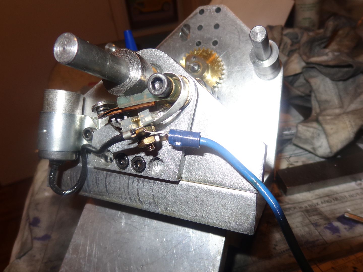
There now---I can't honestly say "We have ignition!!!"---But when the time comes, at least I have the points, cam, and condenser mounted. This is all stuff I recycled from the "Rupnow Engine" when I changed it to a CDI. Why are there 4 bolts holding that tiny little points bracket on you ask?--Well, its a recycled part, and the two outboard holes would have required tapping into two bolts in the front bearing plate that just happened to be in the exact same place. So--I drilled two more holes inboard of the original two. I will probably just cut the heads of an extra pair of #8 shcs and Loctite them in to fill the two original holes.
 
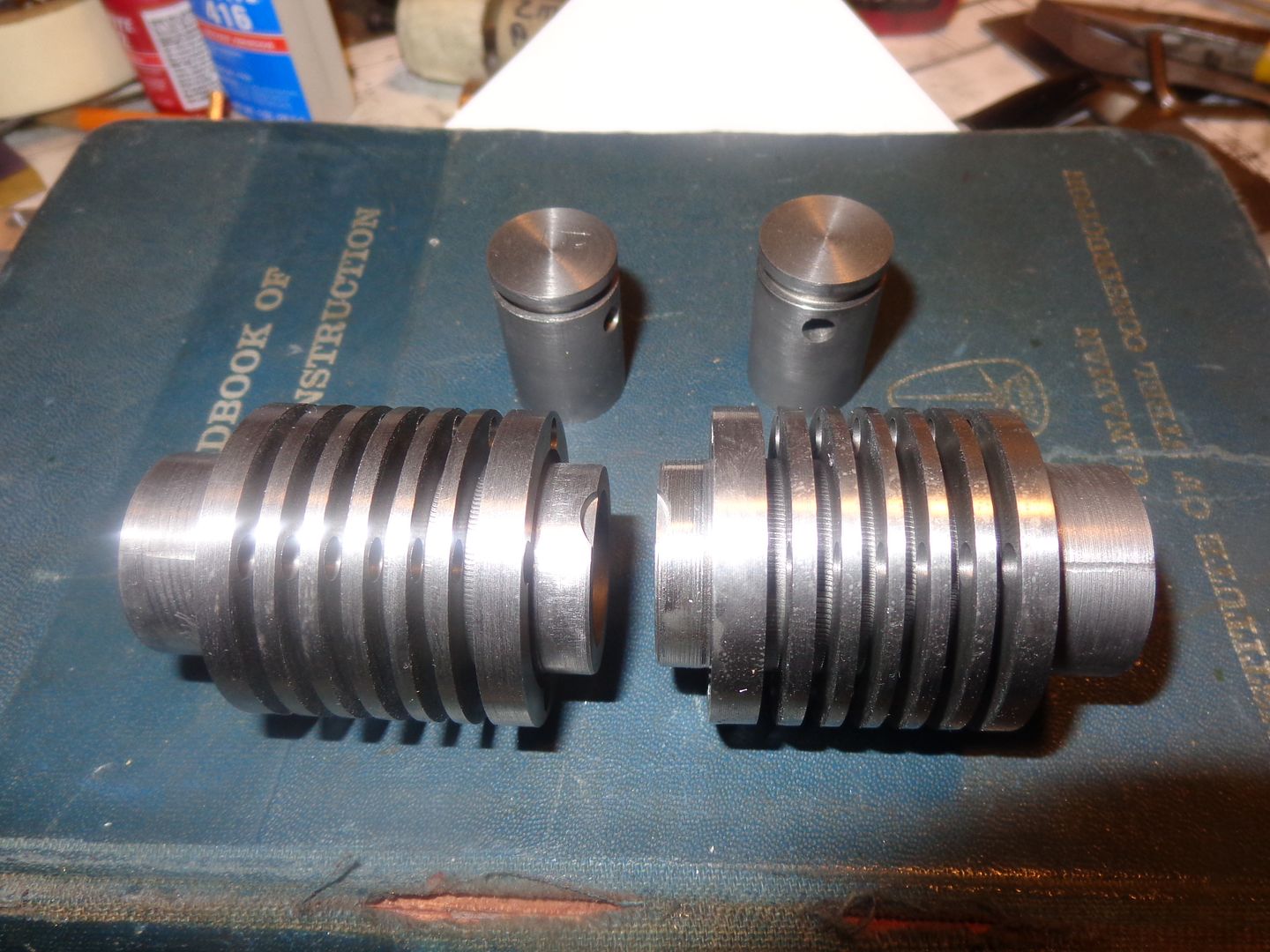
This is primarily an "interest shot" to show the recess that I put in the top of both cylinders to clear the head of the exhaust valve when it opens all the way. I had initially thought that I would need the same recess to clear the end of the sparkplug and the intake valve, but I have realized that the intake valve never opens far enough to create an interference, and the sparkplug is just short enough not to cause a problem. The total lift on my cam is 0.160", and I wanted to make sure that I had clearance under the head of the exhaust valve when it is fully open. I have just finished lapping the pistons into their respective cylinders with 600 grit lapping paste, and then washed them thoroughly in a pan of varsol, then blew them off with the air hose. When I walked back into my office from the main garage, I though this would be the only time those recesses are going to be visible, so I should take a picture. When the cylinders are installed in the center block, there is 1/4" between the ends of the cylinders, and the pistons come right up to the very end at top dead center.
 
Hi Brian:

Concerning your issue with not being able to insert the valve with the valve cage in place. Without the benefit of the pieces in front of me, it would appear that perhaps the valve stem, spring, rocker arm pivot tower etc. etc, could be shortened enough to make the valve short enough to fit inside the head and able to be inserted from the inside - No?
You seem to have an awful lot of valve stem above the head.
(A lot of rework I know)

Certainly the valves don't need to open more than about 30thou.
(there is a rule of thumb how much to open a valve based on it's diameter which escapes me at the moment, but it isn't much).

Like I said it's tough to tell without going back through all the pictures and drawings.

Looks like you solved the issue anyway.

Nice work !!

Sage
 
I can't believe it!!! All of the mechanical parts are finished. I may use a small model airplane carb on this for its initial "start up" phase. I'm waiting for Chuck Fellows to come up with the "perfect" carb design before I build a carburetor. All I have left to do is to drill and ream thru the main backplate and the center plate which supports the cylinders for a couple of locating dowels and put a keyway in the crankshaft for the flywheel. JWCNC has assured me that he is working on the two arms that he volunteered to make for me, and has told me he would be shipping them to me today. I have to design/build a starter hub/pulley combination for the front of the crankshaft, but I'll do that this weekend. I just checked, and I started the design of this engine on the 18-December. Tomorrow will be the 18-January.--Its amazing how much you can get done when you don't have any other work to do!!!
 
Last edited:
DSage--I may have been over cautious when I drilled the thru holes. It seems to me that after having the valves in and out a few times today, they probably didn't need the thru holes. They will (just barely) go in thru the side hole where the cylinder fits on. Oh well, no harm-no foul. Some of these things only become clear after the fact. ---And if I had installed and Loctited things without the thru holes, and then couldn't get the valves out, I'd have been up that well known creek without a paddle!!!
 
I dismantled everything this morning, and cut keyways into the crankshaft. I even learned a nifty trick while doing it. I put the slots in with a two flute endmill. I plan on using 1/8" square keystock, and I knew that a 1/8" endmill always cuts a bit oversize. I hunted around in my cutter drawers and found a 3mm endmill, which is 0.118" wide. I made successive .005" deep cuts until I had reached the desired depth of cut, then offset the table .004" to each side in .002 increments, and came up with an exact .125" wide slot. The missing .001" I put down as cutter side deflection.
 
Last edited:
The nice thing about cutting your own keys and keyways is that when you're in the first assembly for trial fits you can make keys that work but are loose enough to get out easily. Nothing more irritating than a key that won't budge.

Cheers,
Phil
 
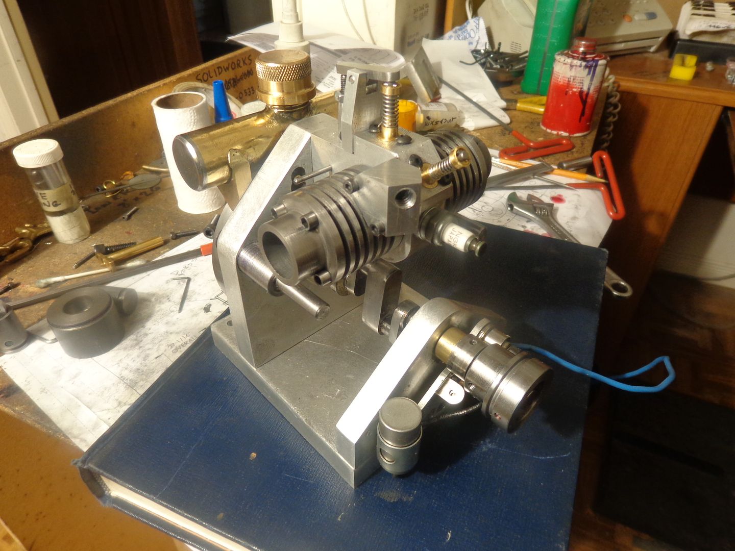
Well---There it sets. There is nothing more that I can do until I have the two arms which are supposedly somewhere "in shipment". I haven't cut the slots in the bottom outer end of the cylinders yet. I won't do that until I have the "arms" to fit to. I need a small break now-----but not too small I hope. I want to get those arms on and see if this thing will run.

 
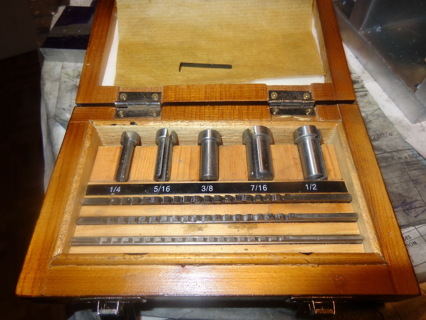
Sage--I use a broaching kit which I purchased from Littlemachineshop.com It will work on hubs of 1/4", 5/16", 3/8", 7/16", and 1/2" bore diameters. The hubs fit into the bore of the pulley or whatever you want to keyseat, and the broach is pressed down through the slot with a manual arbor press. Each tooth on the broach sticks out a few thou farther than the teeth ahead of it, so by the time it is pushed all the way through, the keyway is formed. If the keyway is not deep enough at that point, you can put the spring steel shim (pictured laying on the lid) in as a spacer and push the broach through again. It works on aluminum, brass, and cold rolled steel pulleys.
 
It seems I am going to have a "time window" on my hands now, until my CNC'd arms show up here. I think I'm going to get very bold and be the first to build a "Chuck Fellows Carburetor" to run on this engine. Chuck has done some outstanding research into a small carburetor which has a built in throttle on it to control the speed of the engine. My only previous success with carburetors has been on the simple "one speed" carburetors as used on hit and miss engines, where the speed was controlled by the governors. I've had a couple of bad scares when starting these small hit and miss engines without the governor hooked up, and had the engines "run away"--that is rev up uncontrollably until I could either pull the sparkplug wire or get my finger over the carb throat to "choke it to death"--sure gets the old adrenalin flowing!!!
 
Last edited:

Latest posts

Back
Top