A different opposed piston engine---

Home Model Engine Machinist Forum

Help Support Home Model Engine Machinist Forum:

This site may earn a commission from merchant affiliate links, including eBay, Amazon, and others.
I've had a couple of bad scares when starting these small hit and miss engines without the governor hooked up, and had the engines "run away"--that is rev up uncontrollably until I could either pull the sparkplug wire or get my finger over the carb throat to "choke it to death"--sure gets the old adrenalin flowing!!!

I'll bet it does...

Anyway nice set of broaches. I keep threatening to treat myself to some, but I don't have any spare arms n legs.
 
>>I use a broaching kit which I purchased from Littlemachineshop.com

Ahhh. You do it the right way :rolleyes:

I asked because I was wondering if you had a crude but effective way of doing it. Like me hardening and sharpening a piece of square tool steel, fastening the flywheel to the mill table and progressively shaving off a bit at a time from the bore with the "tool" in the quill. Effective but tough on the quill. I guess I'd also have to invest in an arbor press to do it right (your way).

I guess I should bite the bullet.

Thanks

Sage
 
>>I use a broaching kit which I purchased from Littlemachineshop.com

Ahhh. You do it the right way :rolleyes:

I asked because I was wondering if you had a crude but effective way of doing it. Like me hardening and sharpening a piece of square tool steel, fastening the flywheel to the mill table and progressively shaving off a bit at a time from the bore with the "tool" in the quill. Effective but tough on the quill. I guess I'd also have to invest in an arbor press to do it right (your way).

I guess I should bite the bullet.

Thanks
Sage

I've only ever had to cut a keyway in a bore once. Fortunately it was an aluminum pulley. I did mine in the drill press, clamped to the middle of the drill table, just as you describe. Tapping the table with a hammer... Not only painfully slow but more steps than stairs. The saving grace was the grub screw sat on top of the key.
 
.

I don't understand why modellers struggle with all that setting up and making exact and tight fitting keys and keyway slots, especially in small model engines.

It is a lot easier just to mill a slot in the face of the gear 3 mm wide x 3 mm deep and use a length of 3 mm silver steel
rod through a simple hole in the shaft.

When the gear is pushed up against the shoulder it is all held together rigid and cannot move.
Also easy to take apart again. :hDe:


.

Assem1.jpg


Assem2.jpg
 
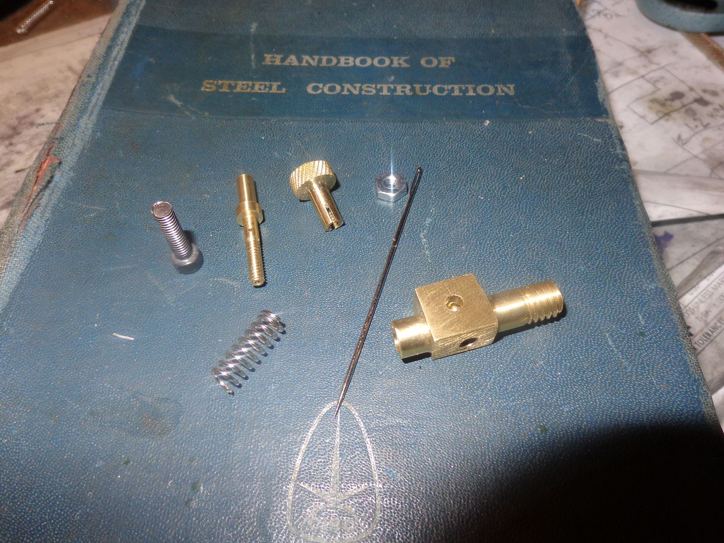
There we have it folks. The "Chuck Fellows Carburetor" Newly minted. I have spent about 4 1/2 hours getting to this stage, which seems like an incredibly long time for such few small parts.--I didn't have to make anything twice. I did not incorporate an "air bleed hole" because Chuck has decided that it doesn't really do anything to enhance the carburetors performance. Drilling the 0.040" holes has a high pucker factor, but it went okay. Now to put it all together----
 
.

I don't understand why modellers struggle with all that setting up and making exact and tight fitting keys and keyway slots, especially in small model engines.

It is a lot easier just to mill a slot in the face of the gear 3 mm wide x 3 mm deep and use a length of 3 mm silver steel
rod through a simple hole in the shaft.

When the gear is pushed up against the shoulder it is all held together rigid and cannot move.
Also easy to take apart again. :hDe:


.

Hi Dave,

I like this idea ! This is one that I shall put in my, not so little, black notebook.
Thanks:
 
Second half of day not nearly as fortuitous as first half of day---Have managed to fill entire carburetor with soft solder---not once, but two times!!! Now I remember why I hate soft solder worse than snakes!! Finally melted everything out, drilled everything out, tapped everything out,and used silver solder to attach needle to needle valve cap. Arrrrggghhhh!! Should have went with silver solder in the first place. Leave soft solder for plumbers!!!
 
I just went through all of the drawings to make sure they were updated, and saved them as pdf files. I still have to do up 3 or 4 assembly drawings with bills of material, and then I will be posting a download link.
 
Hi Brian,

That dam flux gets everywhere :wall: A dab of permanent marker in the right places may help, that is if you can get it where you need it. I suspect that it would be difficult looking at that carb.
 
The drawings are all finished and corrected. There are over 50 detail drawings and assembly drawings. I have saved everything as .pdf files, so you won't need any special engineering software to open the drawings and you can download it from the following link, but be warned--It's a 7 meg download. If anybody discovers a mistake or missing dimension, or there are any missing drawings, let me know. Warning--This is not a project for amateurs. You should have built at least 3 or 4 i.c. engines before attempting this one. The complex shaped rocker arms may need some "fettling" on the end which enters the cylinders, but I don't know how much because haven't got my arms yet to trial fit them. If you decide to build it, please let me know, and good luck. It is a bit unusual for me to release a drawing package before I have a running engine, but I know that everything fits except for the arms, and when receive mine I will post about fitting them in my thread on the forum.
http://www.mediafire.com/download/l5kw3n56pexauty/RUPNOW%20OPPOSED%20PISTON%20ENGINE%20DRAWINGS.zip
 
There we have it folks. The "Chuck Fellows Carburetor" Newly minted. I have spent about 4 1/2 hours getting to this stage, which seems like an incredibly long time for such few small parts.--I didn't have to make anything twice. I did not incorporate an "air bleed hole" because Chuck has decided that it doesn't really do anything to enhance the carburetors performance. Drilling the 0.040" holes has a high pucker factor, but it went okay. Now to put it all together----

Hi Brian,

Where can I see or get hold of the "Chuck Fellows Carburettor" ? A google doesn't get me anything.

Thanks:
 
Thanks Brian,

I wonder why the search didn't find it ?

Anyway got it now.

Perhaps because you spelled carburetor incorrectly!!:eek::eek:--Seriously, the search engine on this forum yields so much information that it isn't all that helpful.---Brian
 
Lacking anything else to do, today became "gasket day". I have found a rather foolproof way to make my gaskets. I simply bring up the 3D model with the surface that my gasket has to seal, (in this case, the exhaust and intake manifolds), and arrange them "FLAT" to the screen and print them at 1:1 scale. This gives the exact size I need. I then cut them out with scissors and use a glue stick to stick them to some 0.030" thick mystery gasket material I purchased in a package of "random gasket material" I have a jar full of very simple gasket punches I have made by taking a piece of round cold rolled steel the diameter I want, chucking it in the lathe, and then running a lathe center/countersink into one end until I have a cone shaped recess with very sharp cutting edges all around. This operation "flares" the end of my punch tool a bit, so I use a bit of 220 grit paper on the o.d. while it is spinning to get rid of the "flare". I lay the gasket on a piece of wood, center my punch on the hole I want, and one light smack with a small hammer yields a perfect sized hole with clean edges. I also have a leatherworkers punch which works really great on the small 1/8" diameter holes. After all of the holes are punched, then I cut out the perimeter with a pair of scissors. Today, I used some nasty black Permatex-2 "form a gasket" on both sides of the gasket before I assembled things. This makes the gasket twice as effective, but then you spend a half hour with Q-tips and paint thinners cleaning up the immediate area and your fingers. I use a little green 638 Loctite where the carburetor screws into the intake manifold, and even a little "Seal all" on the carburetor, where the fuel jet passes through the main carb body. Compression test???--well, at this point in the engine development, I can put my thumb over the open end of one cylinder, and then blow on the other end until my eyes bug out, and not detect any air leaks. I know the piston rings will seal--the Viton rings make that a cinch. If, while I am busting a lung trying to create a air leak by blowing into the cylinder I "pop" either of the valve stems, the air blasts out, then reseals immediately when I release the vale. that is a GOOD sign!!!
 
Last edited:
This is good information Brian. Thus far, I have no gaskets in place on my engine and was thinking about using Permatex, but then it's a mess to disassemble.

I may try this technique out. I have a set of similar punches I made up ages ago.

Cheers,
Phil
 
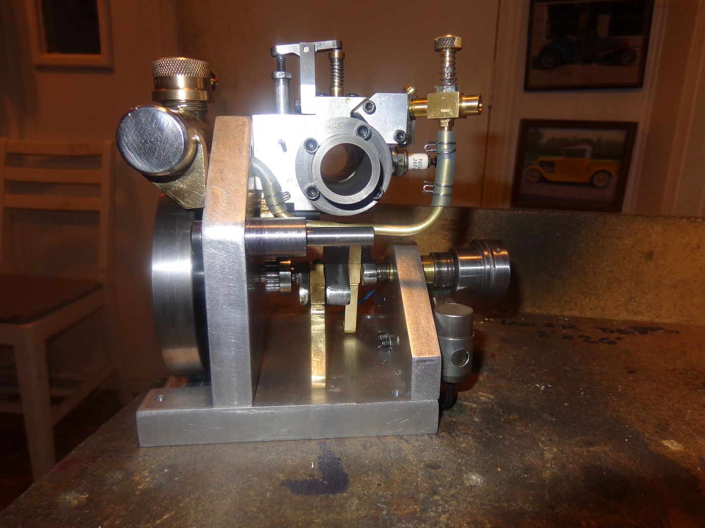
Great care has been taken to ensure that yes, the gas tank really IS lower than the carburetor. That is why the intake manifold has such a wonky shape. I couldn't put the gas tank any lower because of the flywheel, so I had to make an intake manifold that would lift the carburetor up just that teensy bit that makes such a huge difference to how the engine runs. Probably 50% of the problems encountered by first time i.c. engine builders is that they get the gas tank too high in relationship to the carburetor. Since there is no float and needle in these small carbs to shut off the gravity flow of gasoline, the engine will flood terribly and when left unattended all of the fuel in the tank will run out of the carb onto the workbench.
 

Latest posts

Back
Top