A-1 Walking Beam Engine

Home Model Engine Machinist Forum

Help Support Home Model Engine Machinist Forum:

This site may earn a commission from merchant affiliate links, including eBay, Amazon, and others.
C

chiliviking

Guest
I have received my plans for the walking beam engine and have had a couple days to study them and I don’t quite know what to think. It appears that the plans were drawn on CAD and some of the dimensions seem to be just what the program selected rather than a determination using sound engineering and practical sense.

I could cite many examples but will only list a couple to give an idea of what I am talking about. The profile on the outside of the main beam is described as a 14.783 degree cut. Like 15 degrees would be way too much and 14 would not be enough? The radius for a notch on the cylinder cover to clear the valve rod is described as a .100 radius. Knowing that most guys in a home shop environment will be cutting this with an end mill then wouldn’t .093 so you could use a 3/16 mill or .109 for a 7/32 be more practical? I realize that these corrections can be made as you proceed with the project but I am left with the feeling that before any part is made one better study very carefully how this part interacts with the others before making any cuts. To some degree this is a required M.O. to proceed on any project but I have completed many projects where you could build each part to print and everything would assemble as it should. This may seem like knitpicking but the point I’m trying to make is I don’t think I could trust any of the dimensions without some serious checking which will complicate and lengthen the process.

I also have some concerns about the clearances on some parts and the choice of material on a few of the parts. I would really like to get some feedback from others that have had the opportunity to study the plans or better yet if someone has completed the project.

On a positive note it is a real nice design and I think would be a beautiful project when completed.
 
Philjoe5 ...I know you have seen the plans what do you think? Do you see some of the things I am referring to?
 
CV,
The points you are making from are true. However, these points are what I call architectural. For example, the angle of taper on the beam is actually trivial. This engine would work just as well with a rectangular beam rounded at its pivot point. The angle of taper has a ±2º tolerance on it. So make it any way you want. The designer is merely showing the angle they used to make the drawing. Likewise, the notch in the cylinder head doesn’t appear to be critical, but if I later find it is, I’ll notch it with a 3/32” end mill, then advance the workpiece 0.006” and get my 0.100”. My criteria for choosing an engine to build are:
1. It has to look cool and I have to see it running
2. I’d prefer no silver soldering but so far have become inventive enough to get around that
3. I’d like to avoid any screws or fasteners smaller than 4-40

This design meets all of my requirements. I have an advantage in that I’ve seen this engine running and when I did my first reaction was “I gotta make this engine”. I’m also confident that if I hit a snag, the designer or someone on this board or others like it will help me out. I’m halfway through making the cylinder now. I chose that part because it looks fairly complicated. When I first saw the diagram for it, I thought “geez, how am I going to make this”. One step at a time, I expect ;D. I'm making a fixture for it now to make the steam port notches on both ends of the cylinder. Now I can see clearly how to finish this part so I'm at level 2 in excitement mode to get her built ;D ;D ;D. As I said before, if you decide to make it, we can share experiences.

BTW I have no affiliation with A-1, and do not profit by their sales.

Cheers,
Phil
 
Glad to hear that philjoe5 is also building the project it will make it easier having more than one input as to construction. I find it very interesting that you are starting with the cylinder as that was my plan also both from a point of view of getting some of the real complicated stuff out of the way right at the start. Also beginning with the cylinder and working outward from there with perhaps the base as a foundation would be the way I would proceed. I'm only in the sourcing the materials so far I havent started on the parts yet. I think I picked poor examples on my concerns as I realize that there are simple work arounds just using common sense for my examples. Let me give a better example perhap of where someone that hasn't seen the finished project is left in the dark.

The bushings for the main pivot point on the beam are described as two 1/2x3/8 flanged bushings with one pressed in from each side. If they are pressed into a part that is only 3/8 thick then either the bushings need to be trimmed to 3/16 length or as a second choice they could be only pressed in half way with the flanges proud of the beam by 3/16. It just seems to me these should be shown on the prints for those that haven't seen one assembled.

Hopefully we can share some pictures as this progresses.
 
philjoe5....Would love to see the fixture you made for working on the cylinder. I've started on mine but things are moving slow as I am still spending a lot of time trying to figure out these prints. I had the assy. drawing blown up to a size that you can read which helps a little but I still have some real questions. You mentioned earlier that you have some pics of the completed unit, could you email them to me?
 
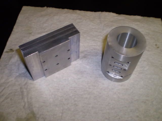
Here's an update on my progress with this engine. I first made a cylinder blank with the usual turning and boring operations. Then I clamped the cylinder in a vise on the milling machine, milled the flat for the steam chest and drilled/tapped the steam chest mounting holes and also milled the steam port slots. Next I made a fixture drilled with the steam chest bolt pattern. Cylinder and fixture are shown here:

cylandfixture.jpg


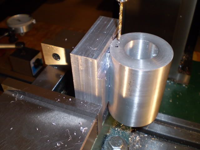
Next I bolted the fixture to the cylinder, then clamped the fixture in a vise on the mill table. Now I can perform machining operations on the ends of the cylinder as shown here:

drillcylonfixture.jpg


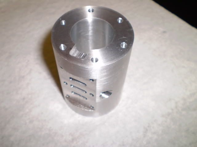
I completed all the machining of the cylinder :big:. It's pictured here:

cylfinished4.jpg


Other photos of progress on this engine will be posted here:

http://s250.photobucket.com/albums/gg261/philjoe5/Walking Beam Engine/

Cheers,
Phil


philjoe5...thanks for posting the pictures and you look to be off to a great start. Im moving rather slowly on mine as I have got the OK from puchasing(wife) to put a DRO on my mill so I think I will wait until I get that done to get serious on my engine. I have got the cylinder started, cut material to size and am looking for sources for the misc. parts( bushings,shoulder bolt, etc.). I also am studying the plans in the meantime. I think I am going to bore mine to 1.125 rather than the 1.040 called out in the plans. As I figure it that will still leave cylinder wall thickness at about .140 in the thinnest spot and will put it at a size that a ring for the piston is available for. I know the plan does not call for a ring but I think I want one on my engine. I'm going to ask for advice from the group in a seperate thread on the ring issue.
 
Really nice job, looks good. Can you tell me where you bought the plans from, would like to get a copy of them.

thanks
Jim
 
Hello, looked at your photos and video on photobucket.Beautiful engine and machining.I would also like to know where these plans are available if you would be so kind.

Thank You,
Lindy
 
Plans are available from:

A-1 Machining Inc.
PO Box 227
Flushing, MI 48433

I still haven't finished this engine but Chiliviking did a fantastic job and his work is published on this board sometime in April - May 2008.

Cheers,
Phil
 

Latest posts

Back
Top