.60 airplane engine

Home Model Engine Machinist Forum

Help Support Home Model Engine Machinist Forum:

This site may earn a commission from merchant affiliate links, including eBay, Amazon, and others.

bikedude987

Member
Joined
Nov 16, 2010
Messages
10
Reaction score
0
Hi, all!

First, I'd like to introduce myself. I am a Mechanical Engineering student at Northern Arizona University, graduating in may. Then it's out into the real world of job searching...

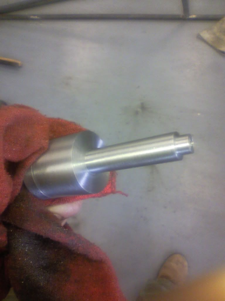
I have been fabricating for about 5 years and machining for about 3. This is my first large machining project where everything is machined, and to tight tolerances and surface finishes. It is also my first engine.

I am building it as a project for advanced CAD/CAM, in which I am currently enrolled. The parts made for the class must use CNC with code generated manually or by using Camworks.

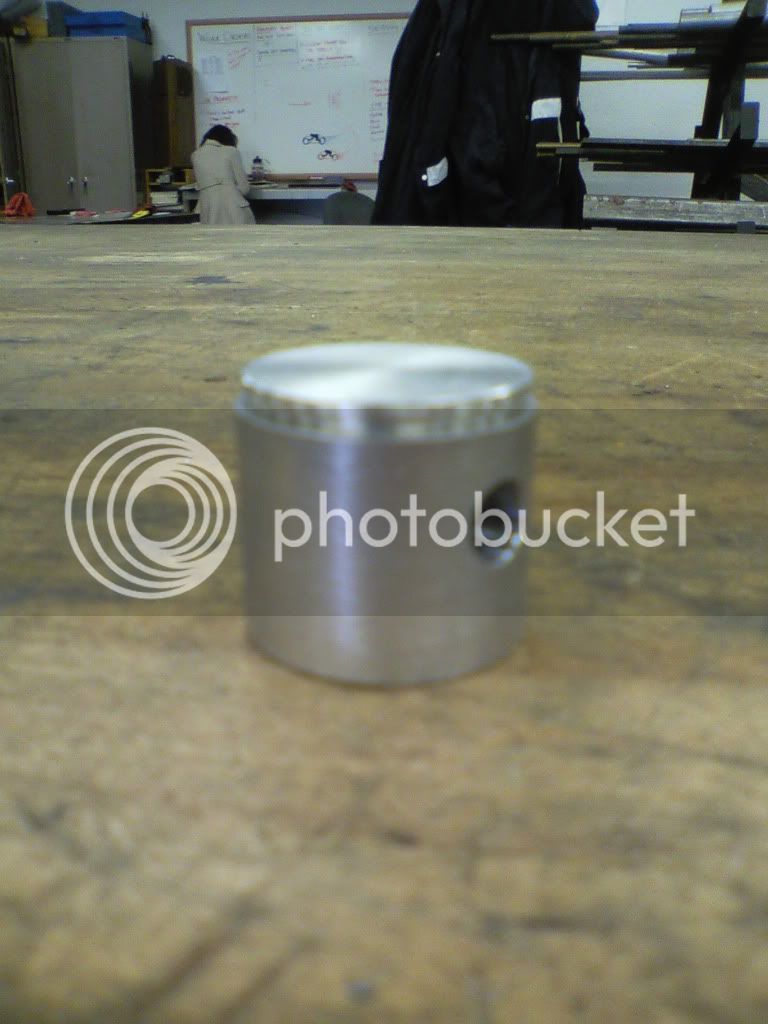
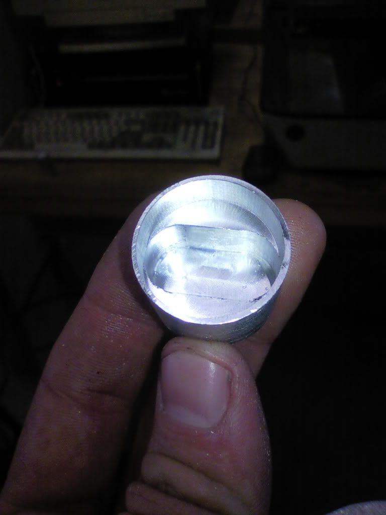
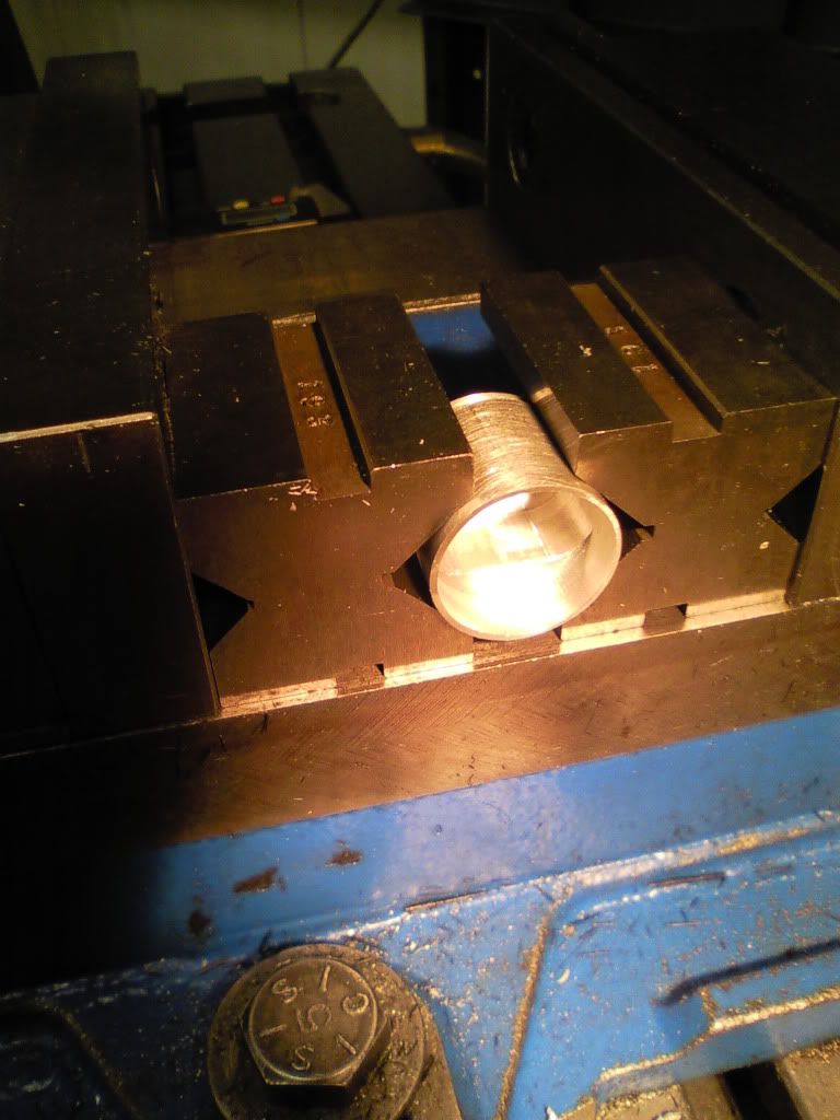
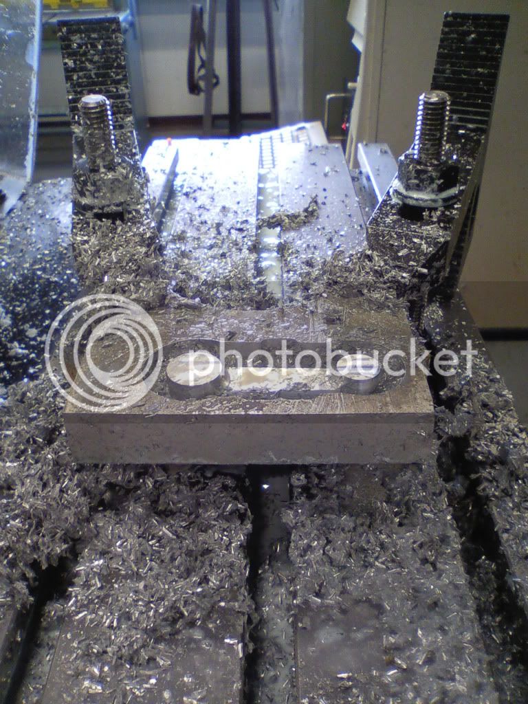
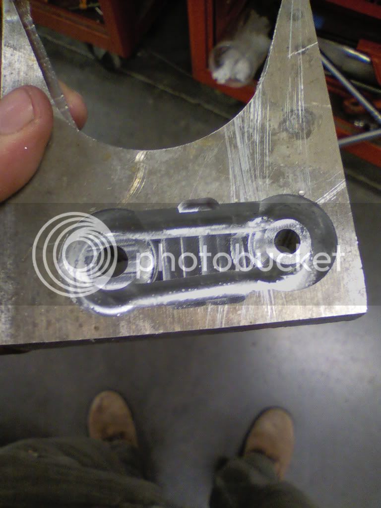
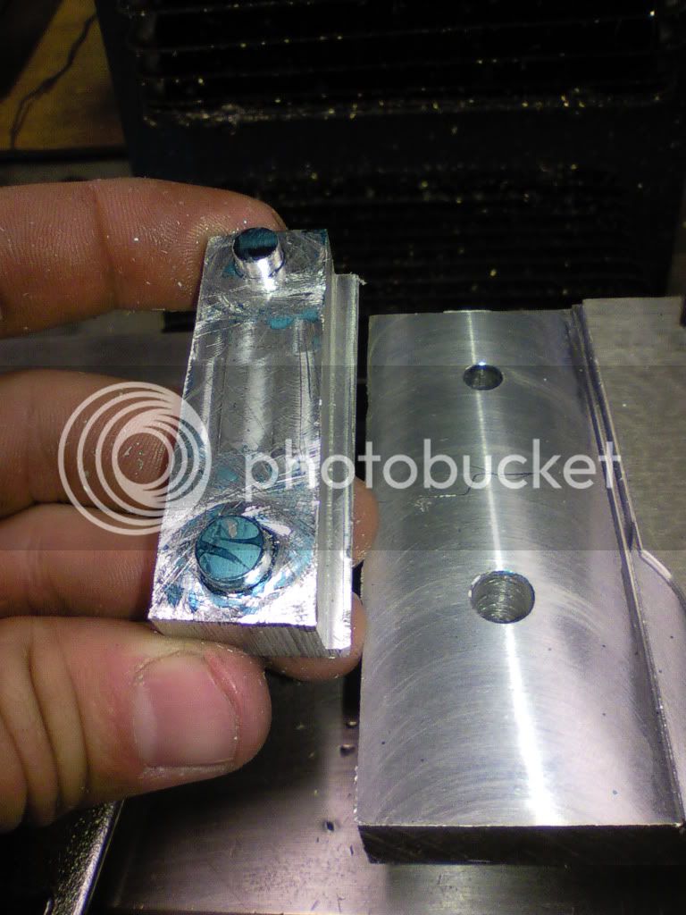
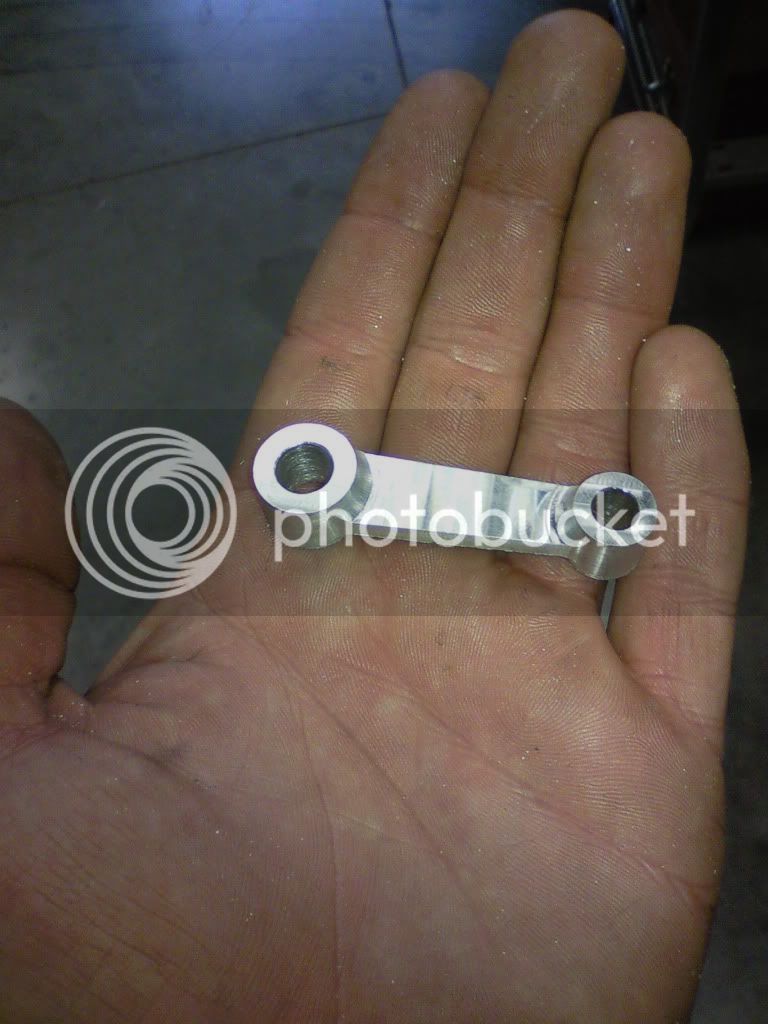
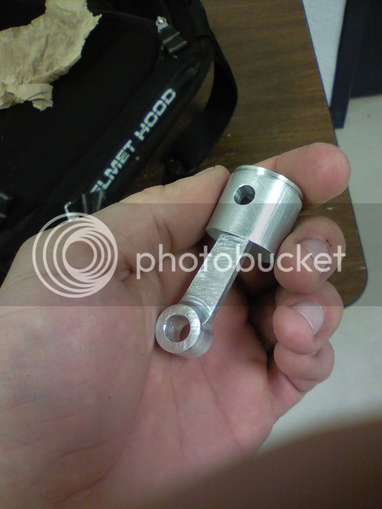
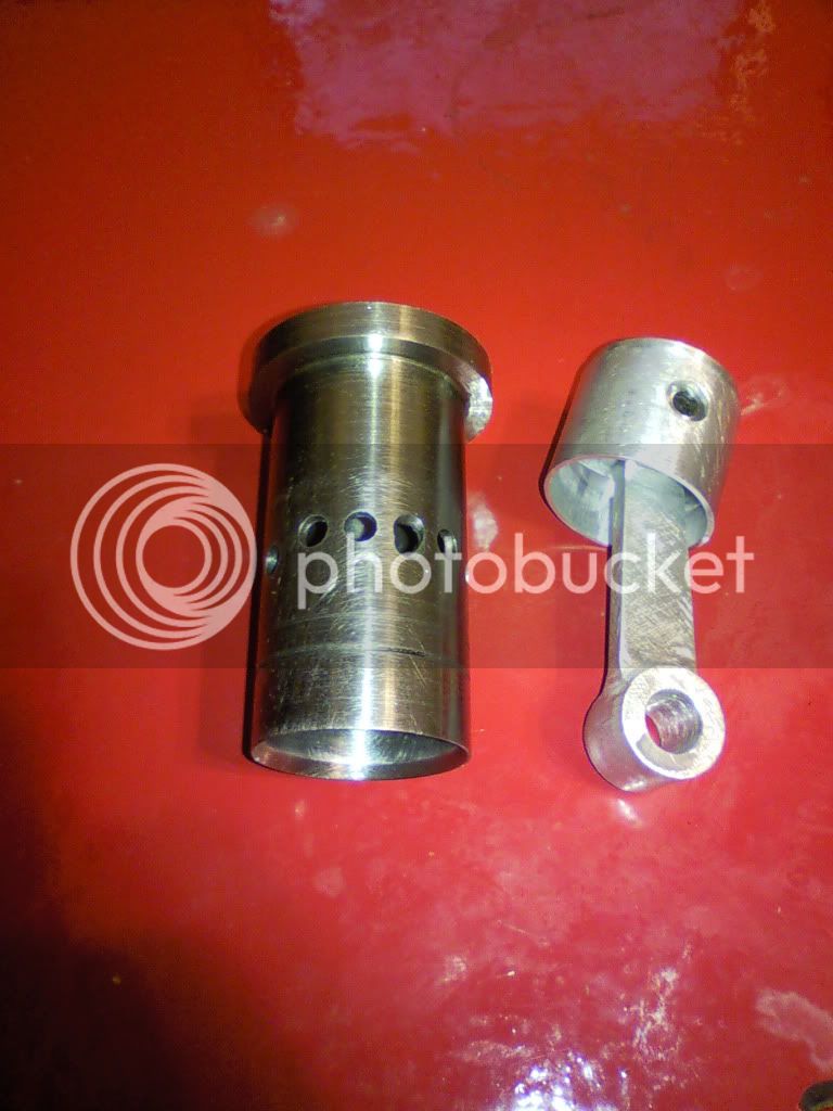
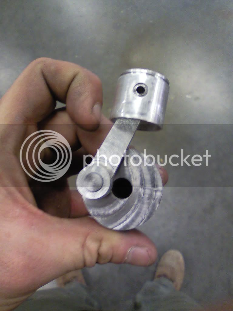
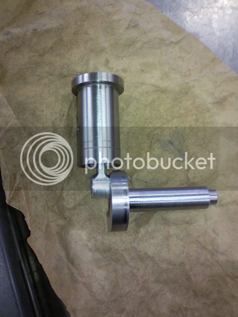
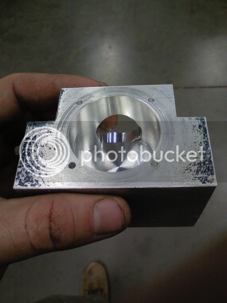
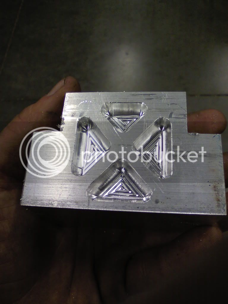
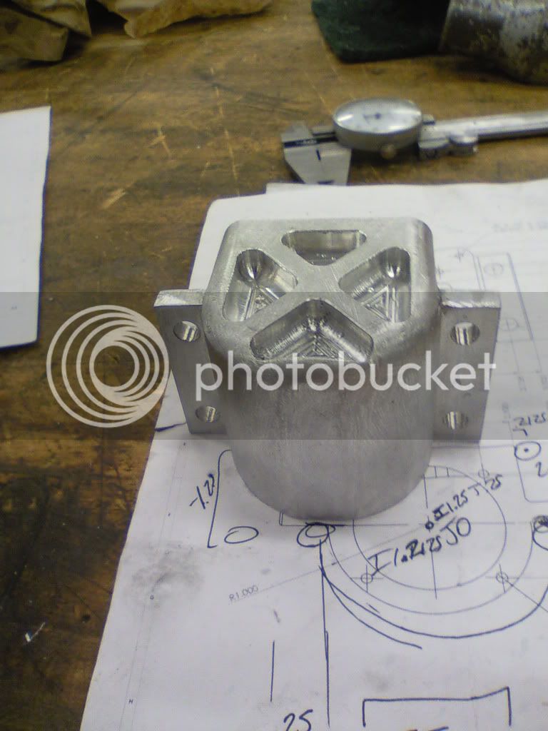
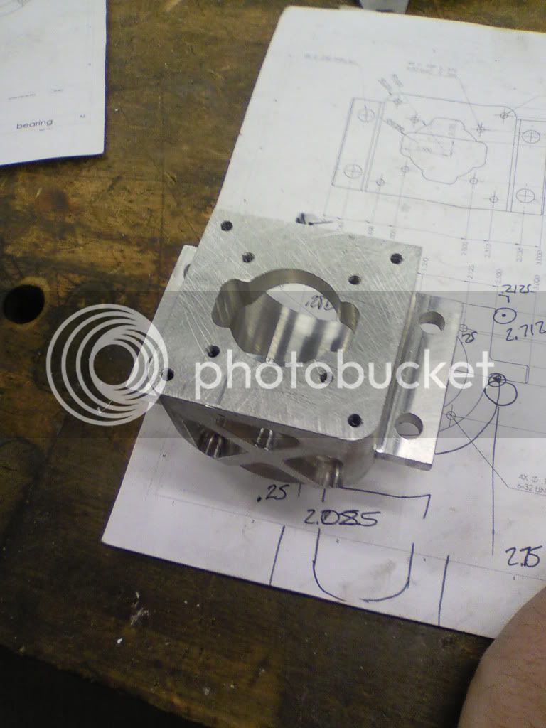
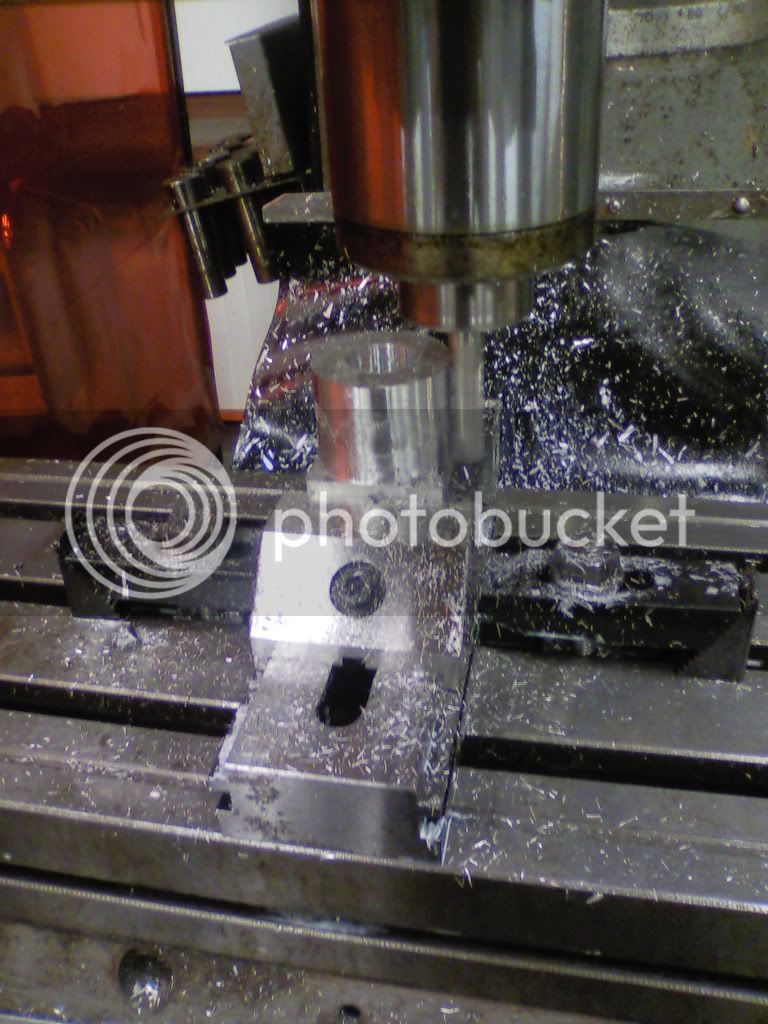
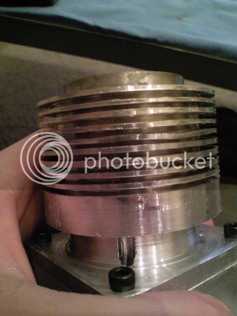
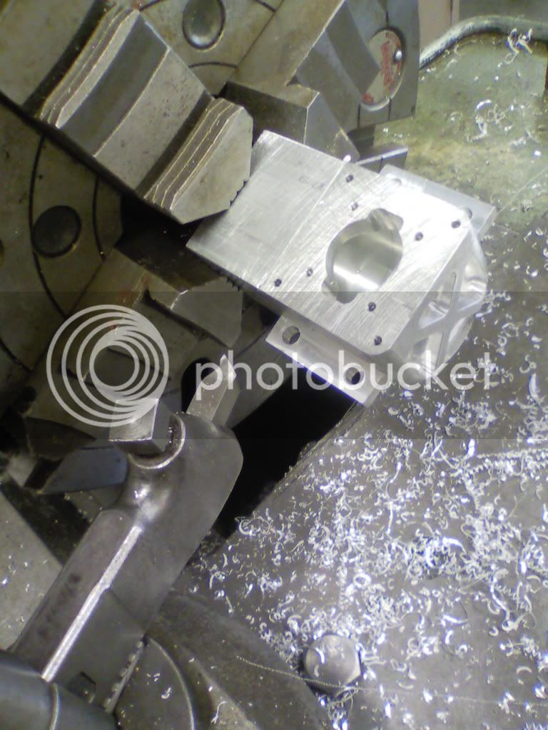
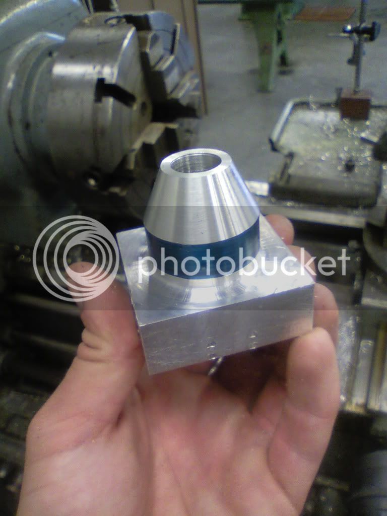
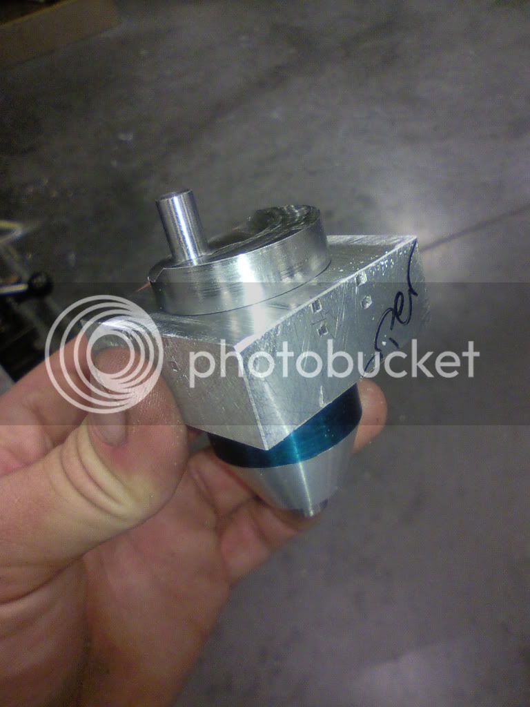
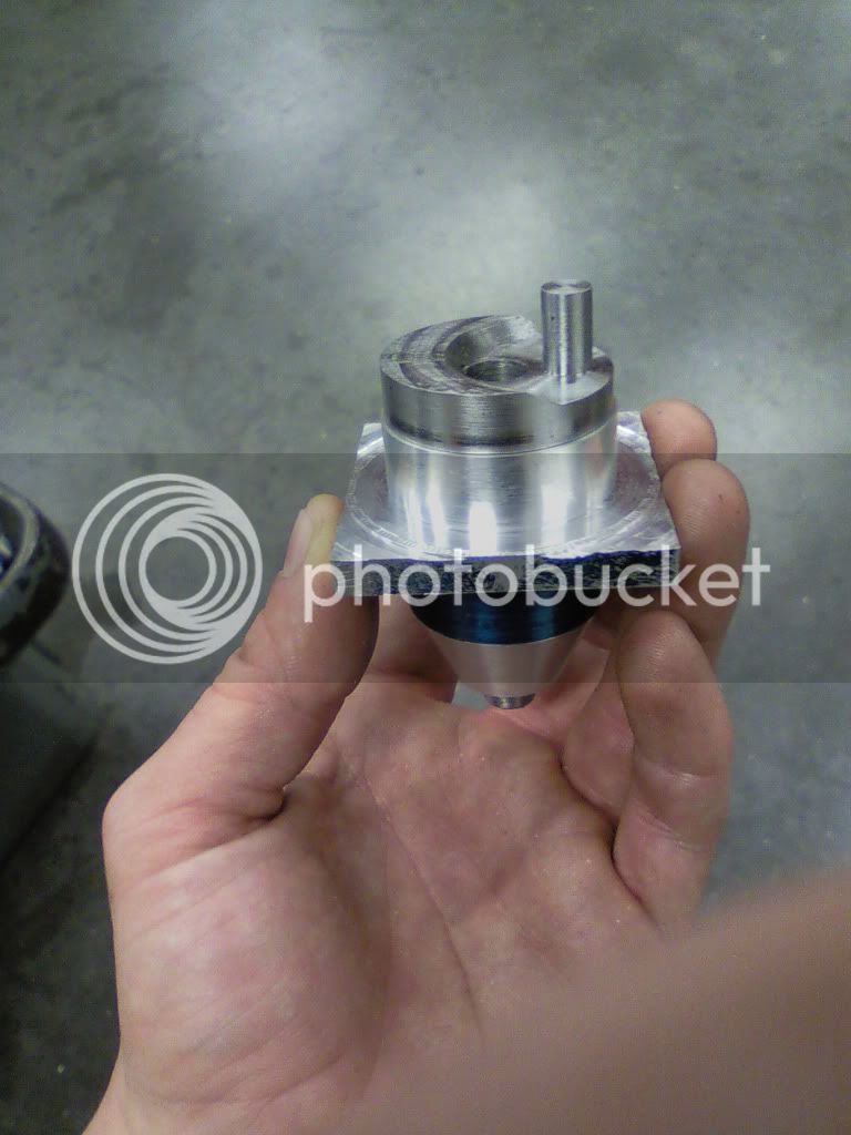
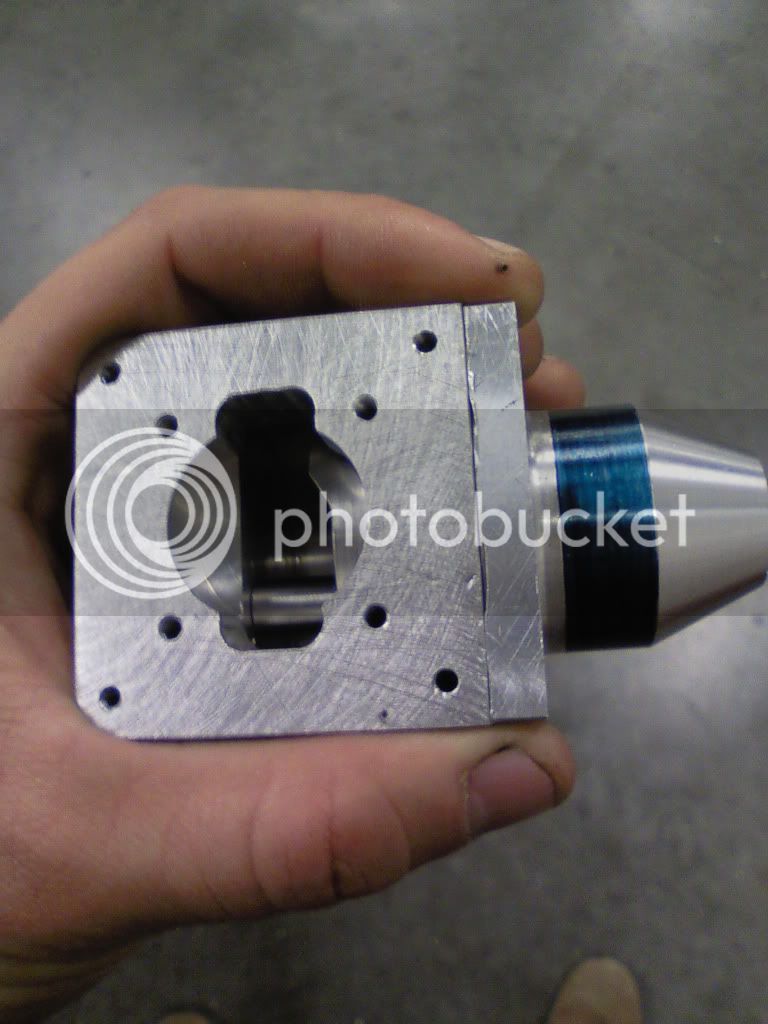
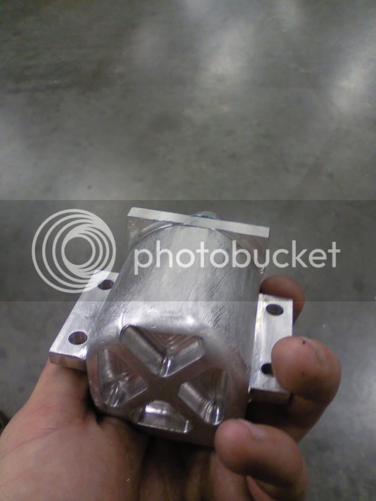
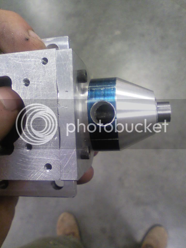
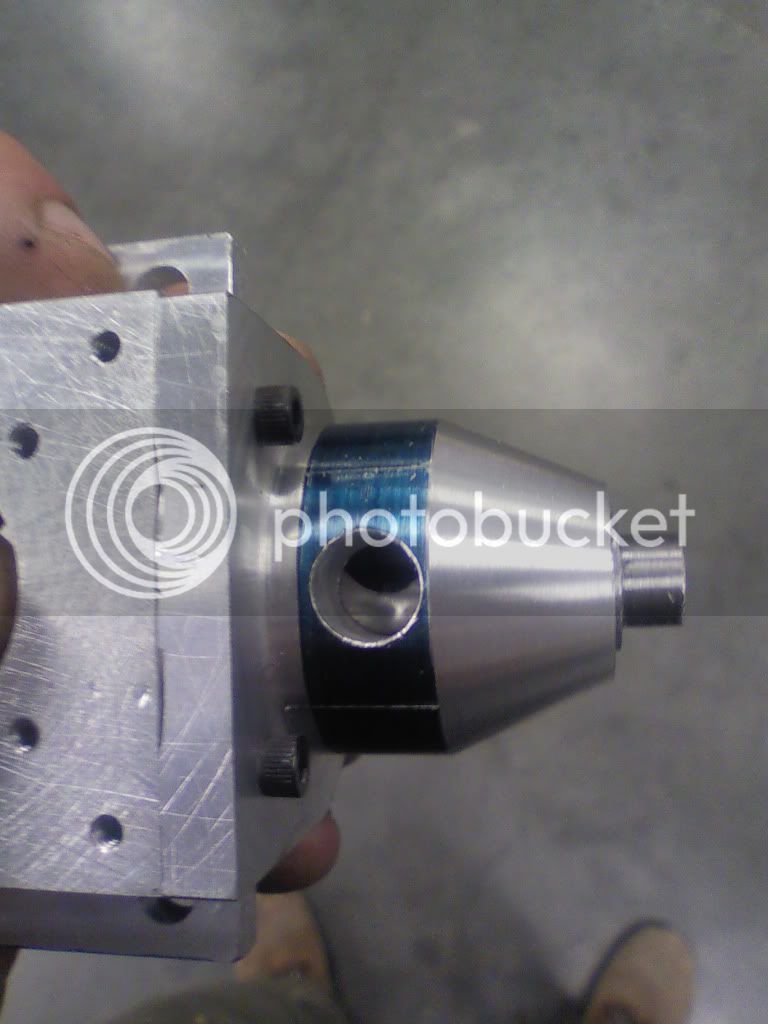
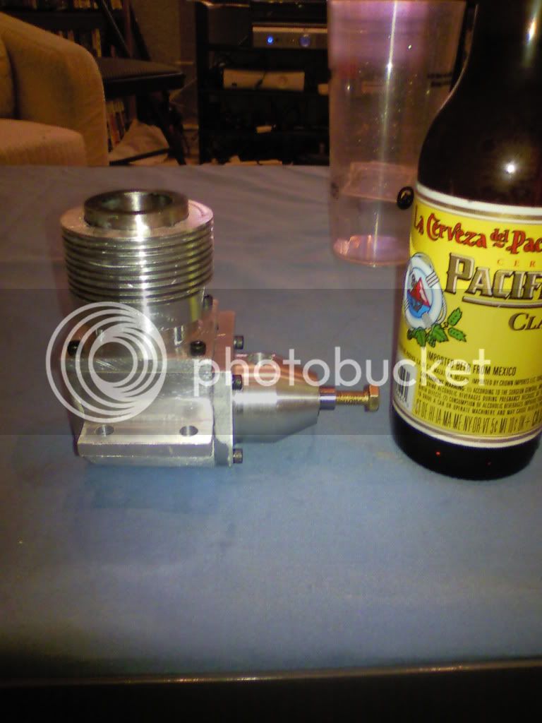
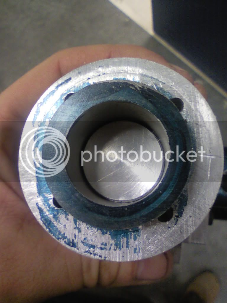
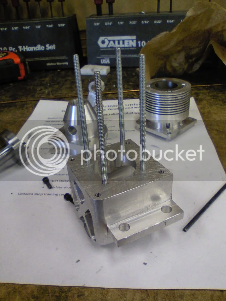
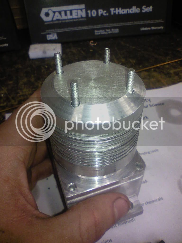
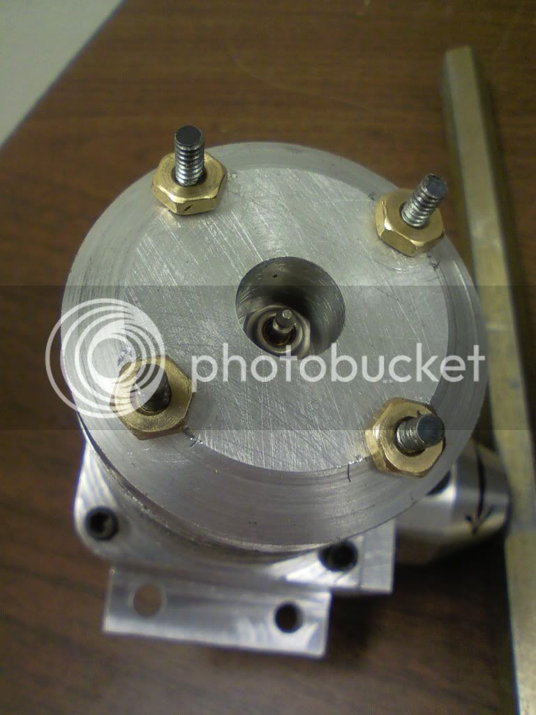
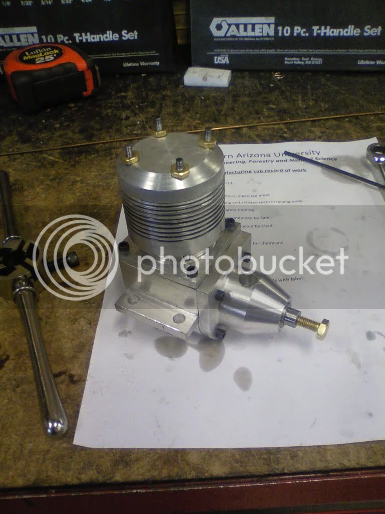
I am building the .60 plane engine from plans found on this site. There were some missing dim's and it is very basic so there are some significant changes, namely to the crankcase, conrod, and cylinder.

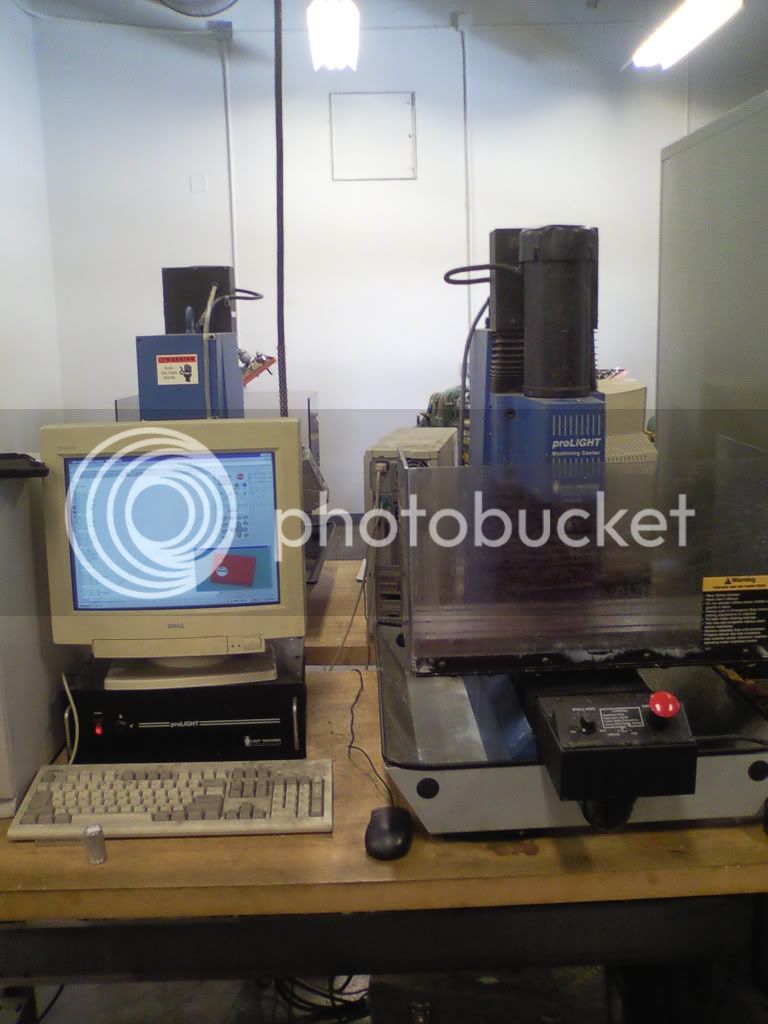
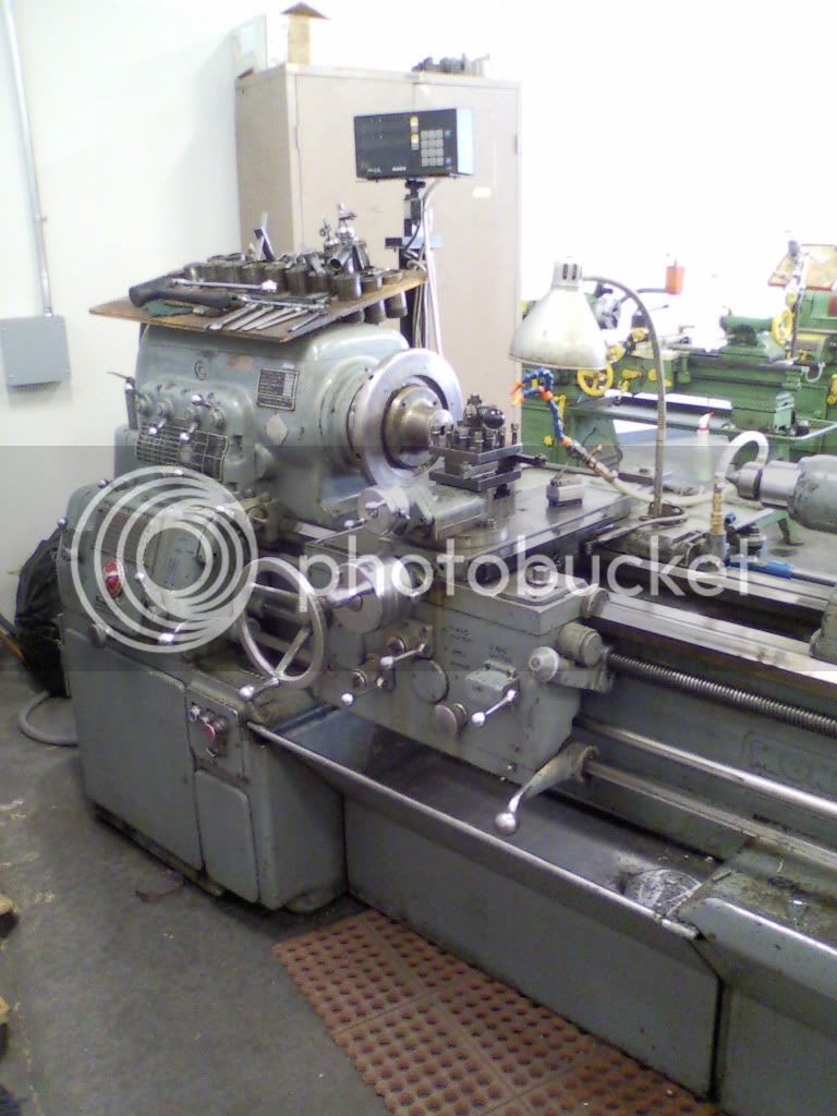
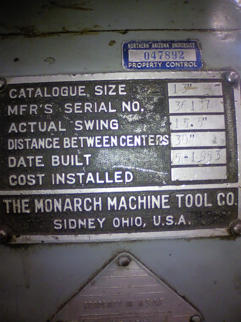
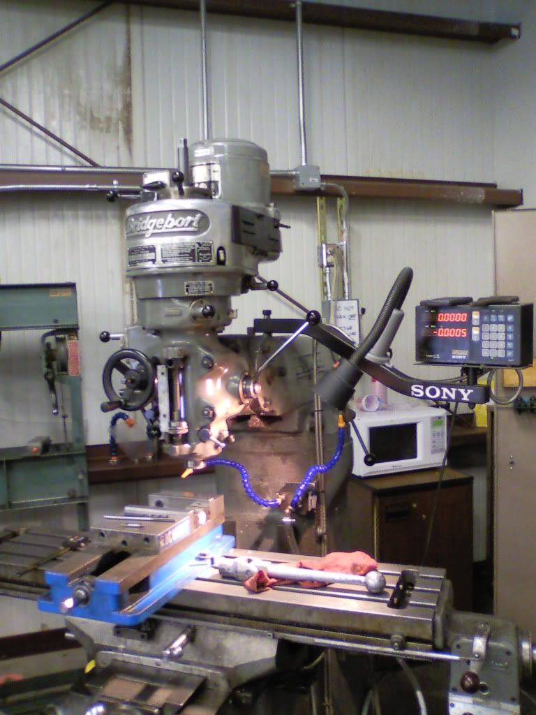
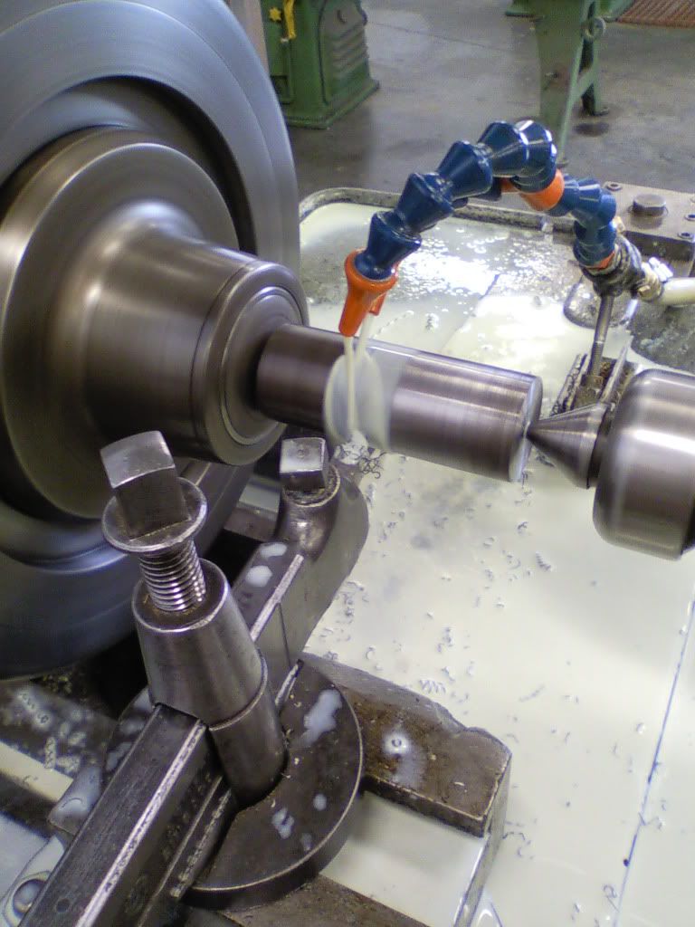
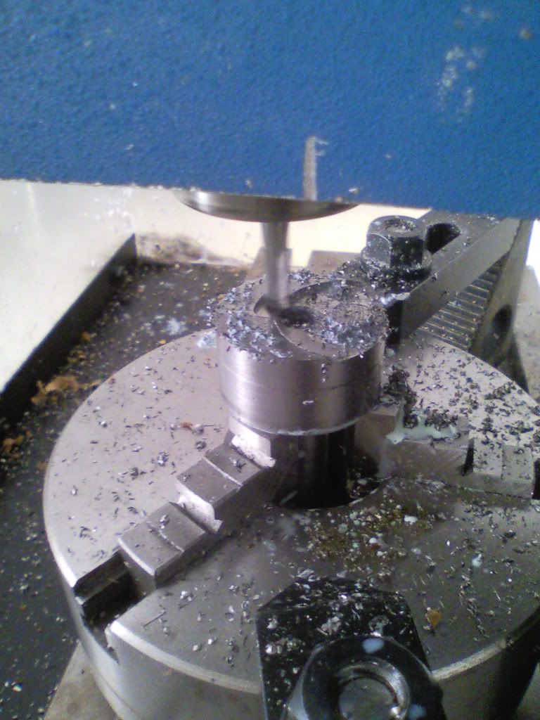
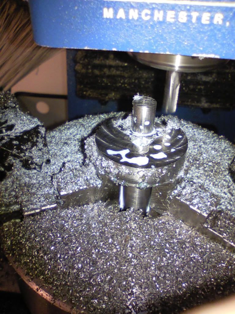
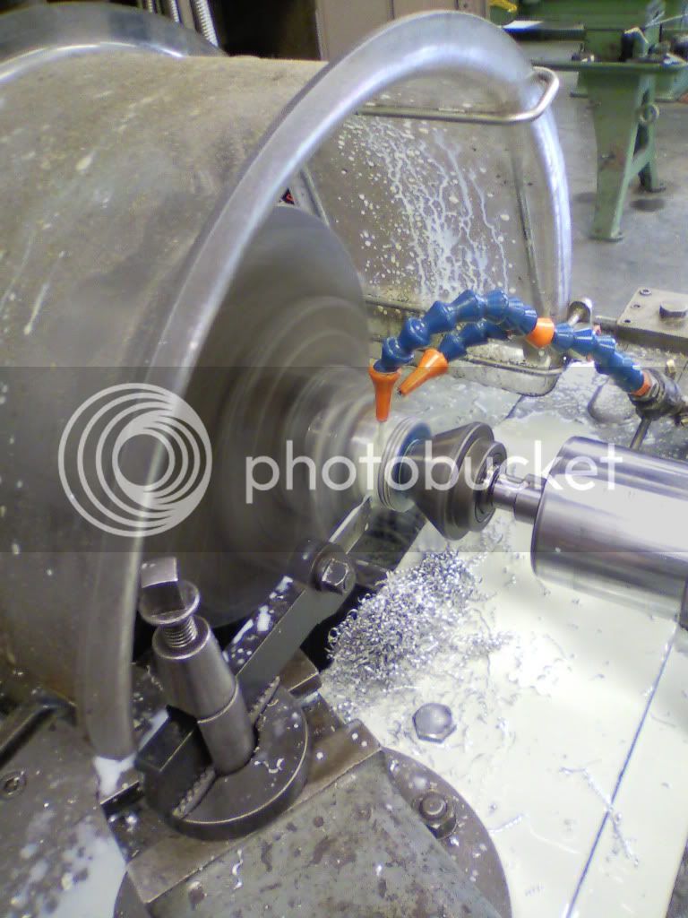
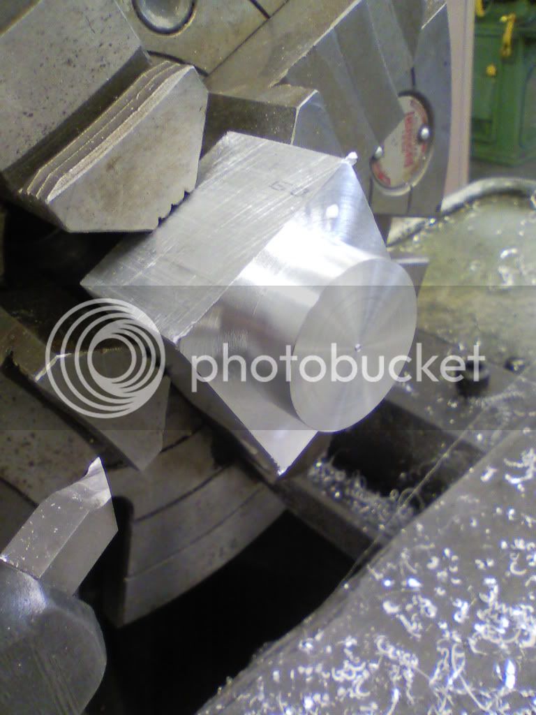
I am mainly using a prolight1000 benchtop cnc mill, a manual bridgeport series 1(?) knee mill, and a monarch 13" engine lathe.
Thanks to all here who have inspired me and given me advice, albeit trolled advice...

I will post pictures when I get a chance, as they are not transferred from my camera yet.
 
Bd987

Welcome to our forum wEc1

Best Regards
Bob
 
Sorry for the long delay, apparently my home computer will only upload one photo at a time to photobucket... so I got on a school machine and we're good to go.

First I'll introduce the machines I have at my disposal (they are the college's ).

A Prolight1000 benchtop cnc mill.
prolight1000.jpg


A 1953 Air Force timed out Monarch 13" engine lathe.
monarch.jpg

monarchtag2.jpg

monarchtag.jpg


and an old Bridgeport knee mill with DRO
0224111434a.jpg


all the machines are pretty clapped out, but they are better than nothing...

First to make was the piston outside features
0224111443.jpg


then to the prolight to hog out the inside
pistonagain.jpg


then the wrist pin hole
wristpinhole.jpg

0224111434.jpg


my drawings were a mix of this and Solidworks generated drawings
0224111600.jpg

 
Then on to the cylinder sleeve, made from an old Jeep camshaft. Turns out it would eat carbide before I tried to anneal it...with great success.
sleevematl.jpg

sleeve.jpg

psleeve.jpg

psbottom.jpg


then into the mill to get the ports. messed up on the first exhaust and spotted it at the same height as the intake. not much went through though, just a weird shaped hole...
0224111600b.jpg

0224111600a.jpg


next was the crankshaft. turned on the lathe...
lathe.jpg

crankblank.jpg


then into the prolight for some fancy while loop code
0301111614.jpg

0301111656.jpg

0301111724.jpg

0301111724a.jpg

0301111736.jpg

0301111736a.jpg

0301111747.jpg


Then onto the connecting rod.
0225111458.jpg

0225111527.jpg


then flipped and aligned
0225111643.jpg

0225111721.jpg

0225111729.jpg

0226111824.jpg


all together
0302111012.jpg

0302111012a.jpg


still needed to make the port in the crank
0302111026.jpg

 
Then for the aluminum bits... picking up stock on my moto.
0303111518.jpg


and cutting on the horizontal
0303111542.jpg


starting the crankcase
0305111519a.jpg

0305111519.jpg

0305111519b.jpg

0305111519b.jpg


onto the supermax cnc mill
0306111425.jpg

0306111540.jpg


done
0306111540a.jpg


starting the cylinder
0307111048.jpg


I hate finning...actually sheared one around half the base.
0307111925.jpg


con ports
0307111924.jpg


0307111506.jpg


next: the bearing block
0306111601a.jpg

0306111601.jpg

0306111640.jpg

0306111640a.jpg

0307110919.jpg

0307110919a.jpg

0307110920.jpg

0307111004a.jpg

0307111004b.jpg


here's how it stands next to a cold one...
0307111908.jpg


jb weld the liner in
0307111607a.jpg


all the parts, plus studs
0308111300.jpg

0308111503.jpg


got the glow plug in
complete.jpg

0308111519.jpg


I have the carb, needs an adapter, and the exhaust... and I think I will try making a ring for it as well.

Until next time...
 
I really really hope you are not going to leave the cylinder head nuts like that. :(

I was enjoying this build until I got to that last couple of pics.
they look a little like that'l do to me.

the rest looks good.


just my two pence.
Roy
 
Nice work!
I will be a runner for sure!
Are you planning to use it in a model?

I agree with Roy, you need to change those nuts! I think it will look great by just adding a recess and some nice and shiny blind nuts ;)

Norberto
 
wheeltapper said:
I really really hope you are not going to leave the cylinder head nuts like that. :(

I was enjoying this build until I got to that last couple of pics.
they look a little like that'l do to me.

the rest looks good.


just my two pence.
Roy

I agree. Maybe a cap to flatten out the surface for the 4 nuts. There is more then enough thread sticking out.

The rest looks great.
 
The engine is coming along nicely...looking forward to seeing it done....nice Monarch too!!!
 
Looks like you are having a lot of fun. It reminds me of some of the good times I had in my shop classes back in high school. May I offer these suggestions. Counterbore the holes on the top of the cylinder head so a washer and nut will have 100% contact with the head and to incorporate some ball bearings on the shaft or at the very least a self lubricating bronze sleeve bearing. Bare aluminum does not make a very good bearing surface for high rpm's. It will gal up and seize in a heart beat. Thank you for sharing and I will be watching for the run results.
 
Haha...the stub nuts look 'that'l do' because, well, they are. I completely agree they look shitty, and will probably be counterbored in the near future.

as for the bearings/bronze bushing, it would be nice, but i doubt it will be a runner, more likely a conversation piece on the desk. I will try to get it to run, but past one run, i doubt i'll ever fire it again. too many other things I would rather do (like make a different engine!)

As it is, I don't have a lot of time as working on machining my capstone project...so I'll get back to this when I can.
 
Fun looking project! What are you building for your capstone project if I may ask?
 
Sure, It is a measurement fixture that will be installed as a quality control measure after injection molding of wind turbine blades (fiber reinforced plastic of unknown variety...). It will measure the angle of attack at the tip compared to the mounting surface.

I wanted to do mini baja, but oh well....
 

Latest posts

Back
Top