


- Joined
- Jun 4, 2008
- Messages
- 3,285
- Reaction score
- 630
I decided to upgrade my CNC mill by adding a 4th axis. They're very useful for gear cutting, and potentially other jobs. Unit is basically your Chinese 8" rotary table with the manual handle replaced by a stepper motor. My mill's controller already had the electronics to drive it, so it was pretty much plug and play. Novakon provided me with a Mach3 profile that had the basics for controlling it, and I just needed a few configuration mods to get it moving.
First job is to mount a chuck to the table. With the table mounted horizontally I centered it under the spindle.
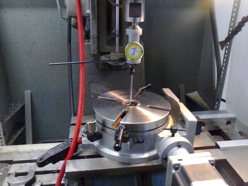
That turned out to be a waste of time since I found that I didn't have enough Z space to use the same center finder with a rod held in the chuck. So went to plan B using a DI to center the chuck, which I just moved from my old manual rotab.
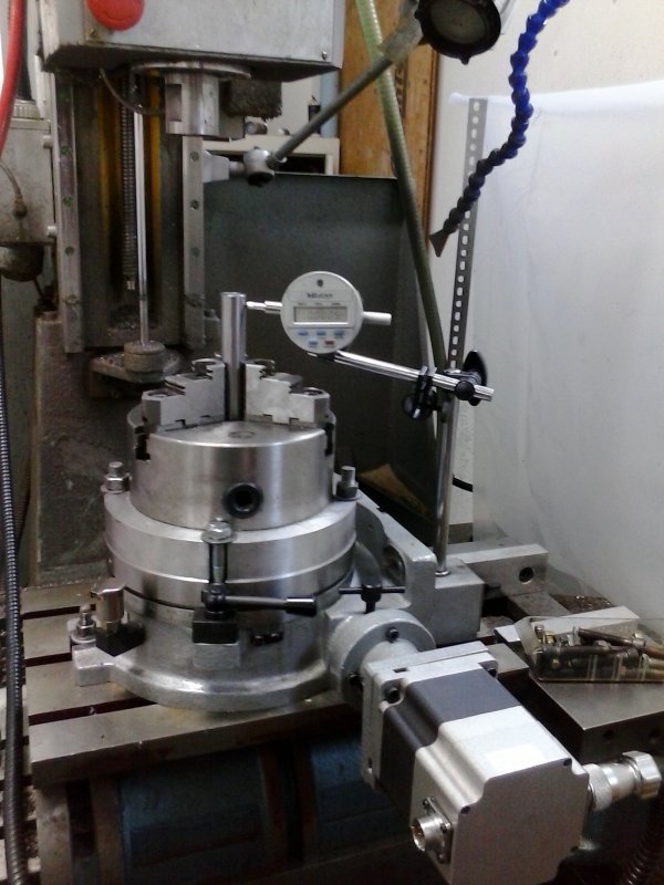
Managed to get it aligned to less than .001" all around, so quite happy with that. Then set it vertical.
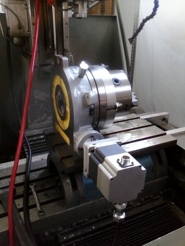
As can be seen, the motor extends out a long ways. I might need to turn it the other direction because the tailstock wants to point from the left:
I suspect that once the aligned the tailstock can be operated OK with its back to me.
First job is to mount a chuck to the table. With the table mounted horizontally I centered it under the spindle.
That turned out to be a waste of time since I found that I didn't have enough Z space to use the same center finder with a rod held in the chuck. So went to plan B using a DI to center the chuck, which I just moved from my old manual rotab.
Managed to get it aligned to less than .001" all around, so quite happy with that. Then set it vertical.
As can be seen, the motor extends out a long ways. I might need to turn it the other direction because the tailstock wants to point from the left:
I suspect that once the aligned the tailstock can be operated OK with its back to me.