4 Cylinder OHV Engine new cylinder head. A work in progress

Home Model Engine Machinist Forum

Help Support Home Model Engine Machinist Forum:

This site may earn a commission from merchant affiliate links, including eBay, Amazon, and others.

gbritnell

Project of the Month Winner!!!
Project of the Month Winner
Joined
Jul 16, 2007
Messages
2,986
Reaction score
1,055
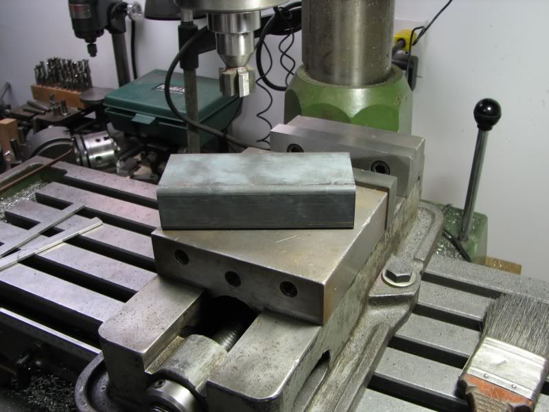
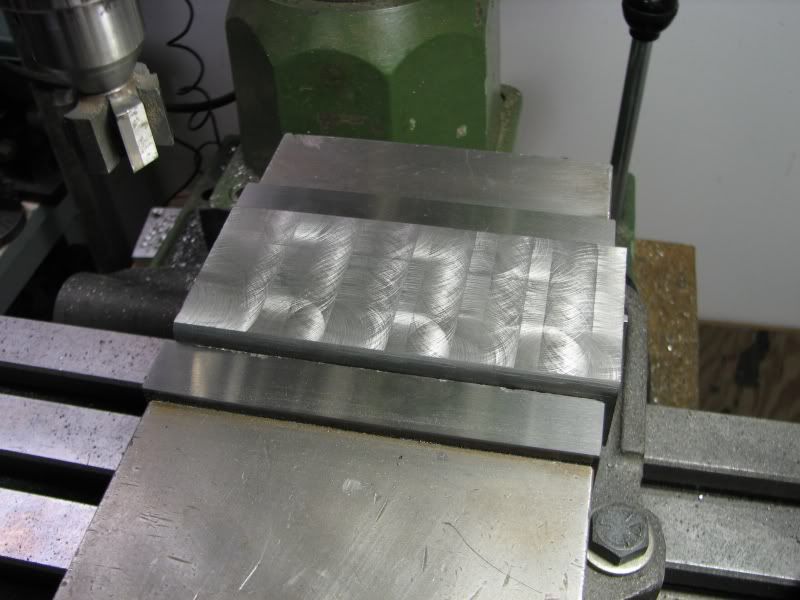
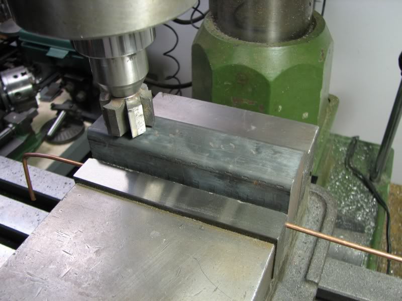
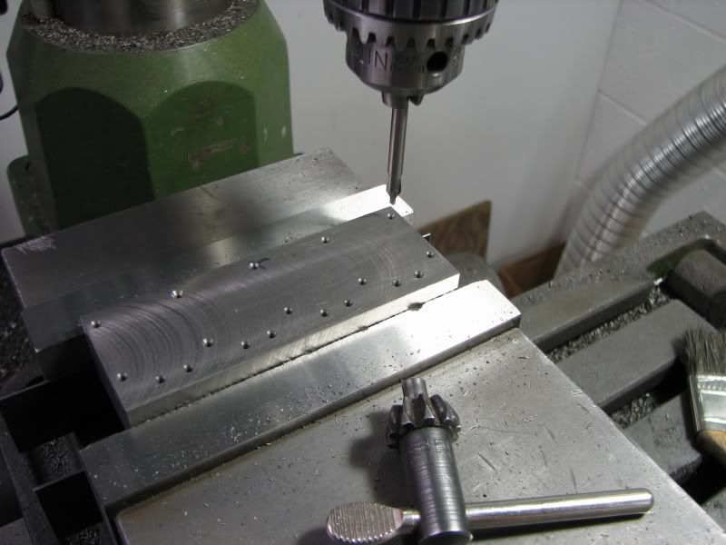
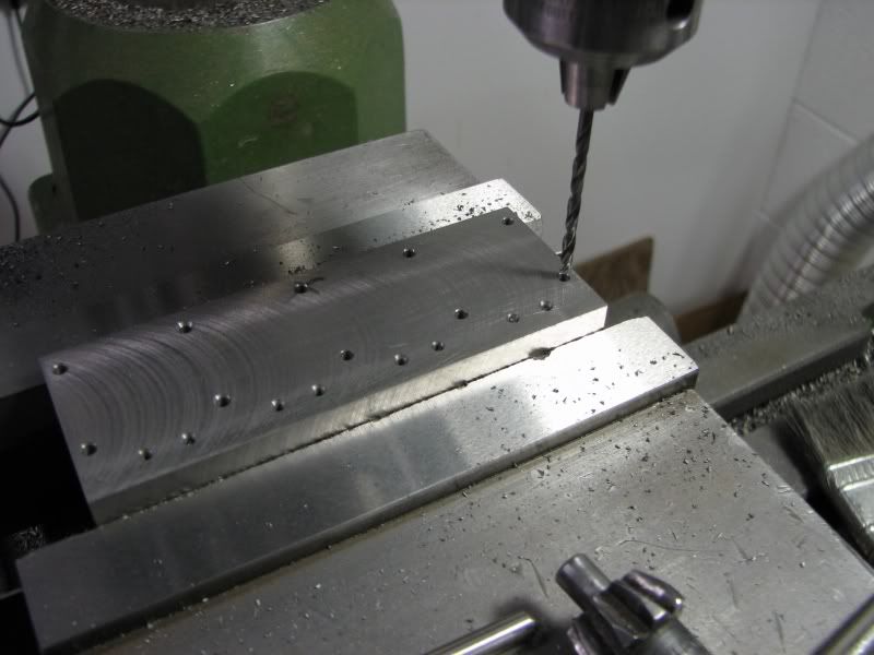
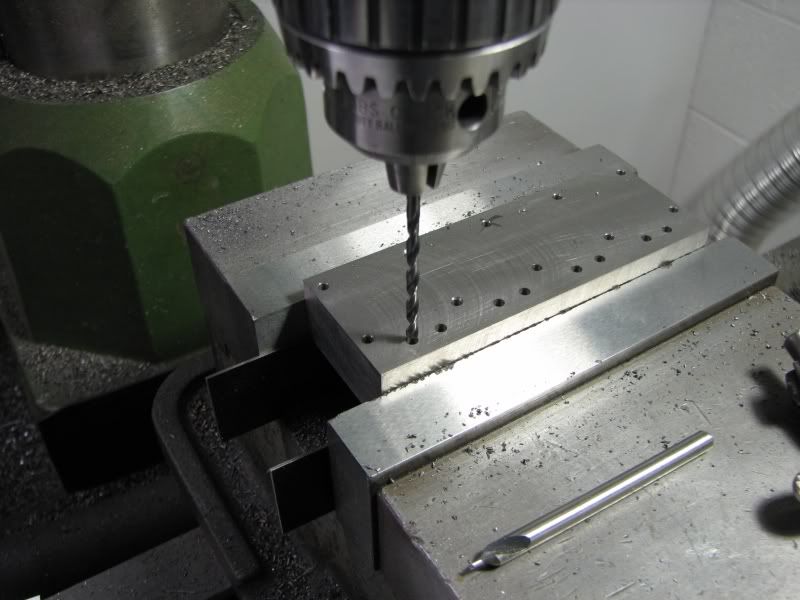
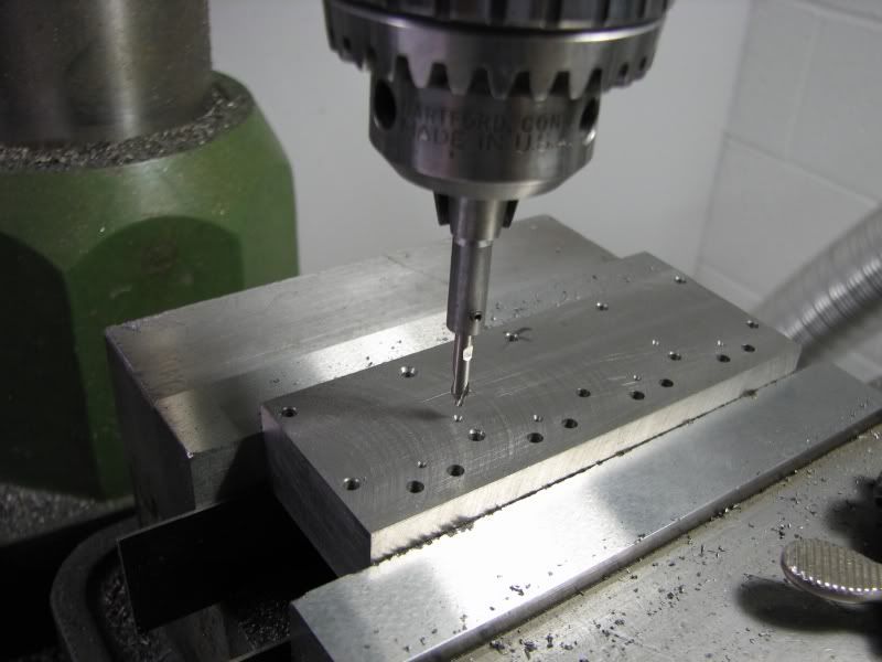
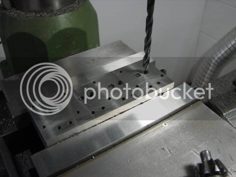
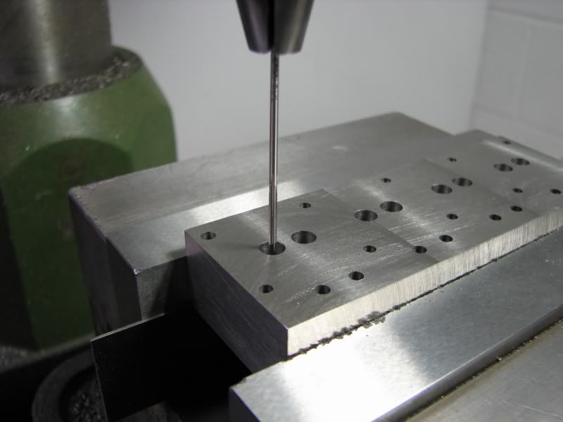
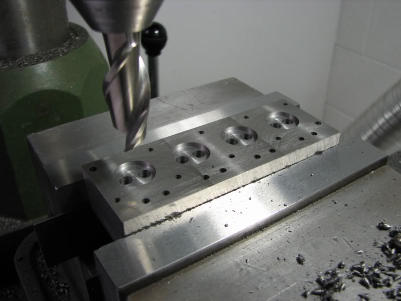
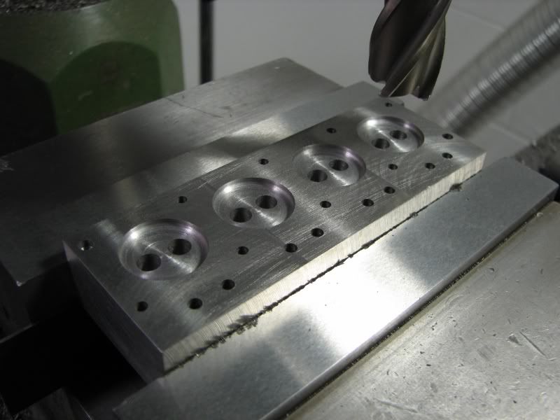
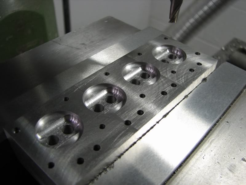
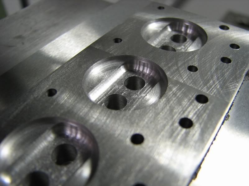
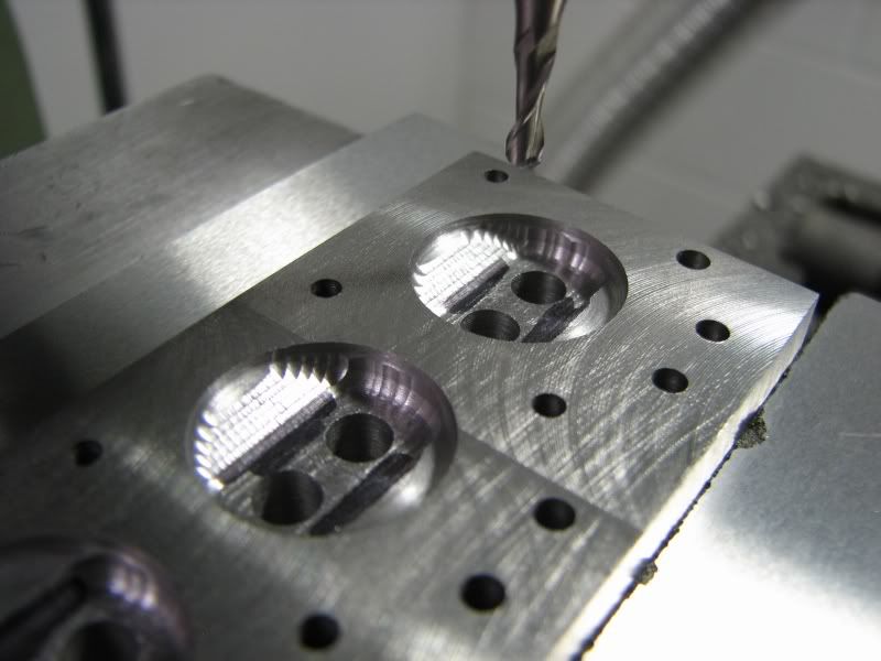
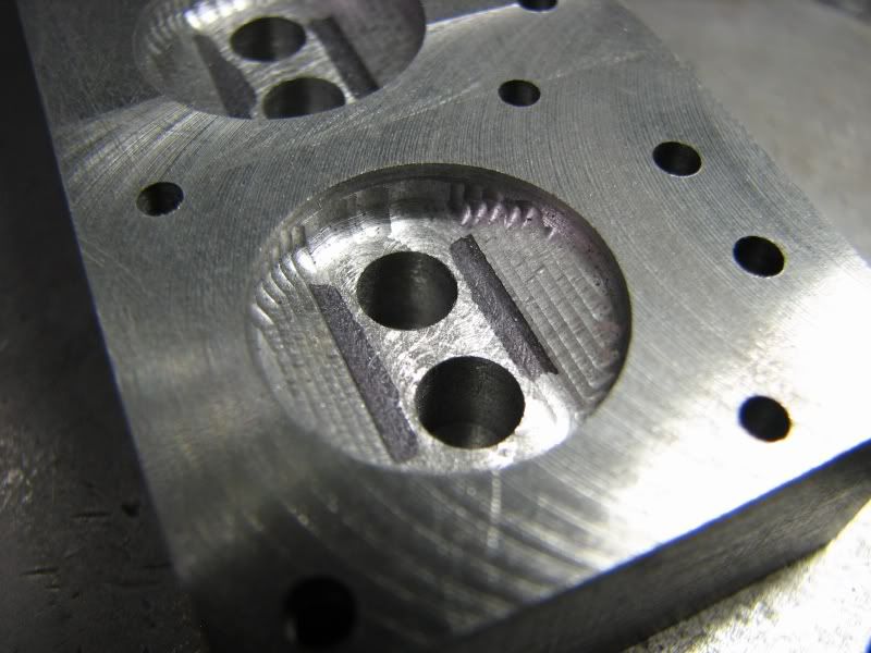
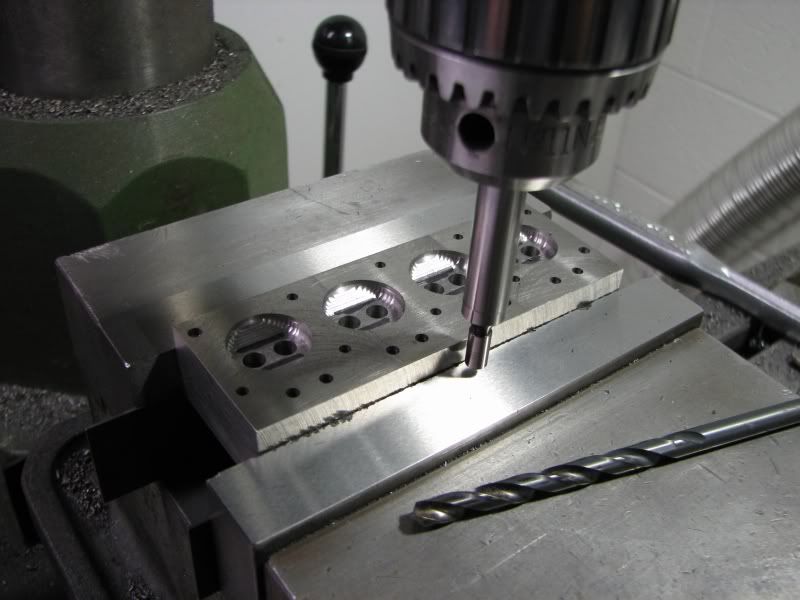
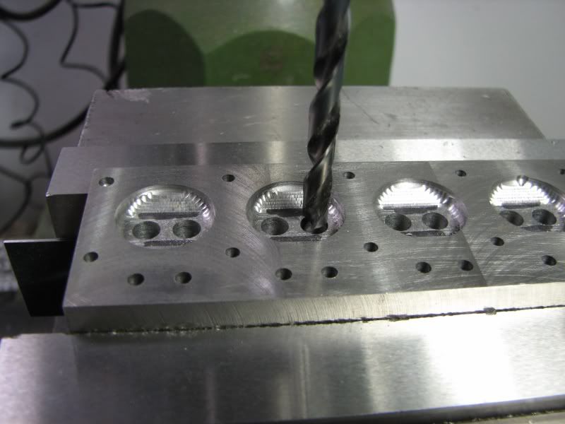
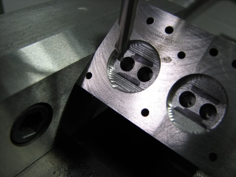
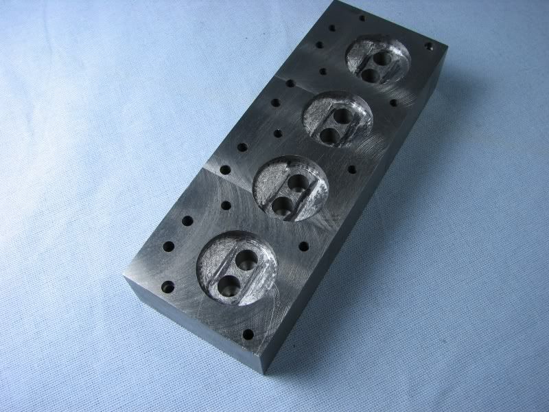
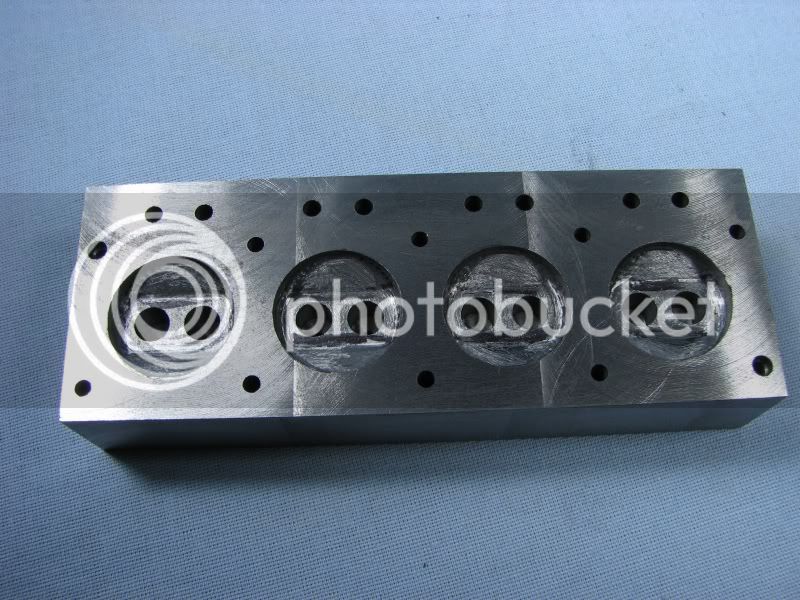
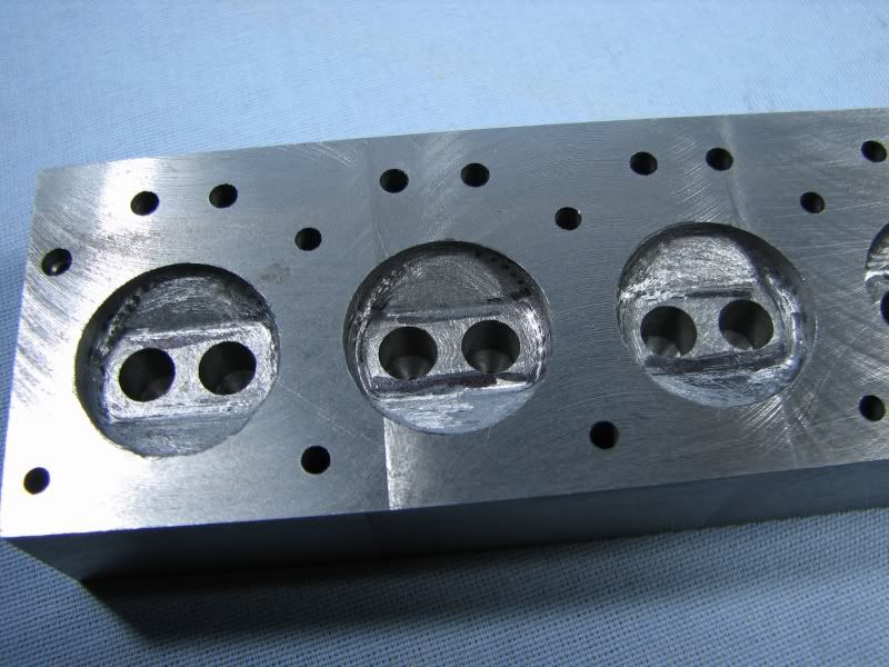
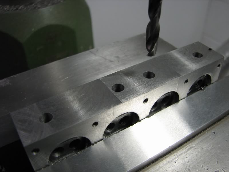
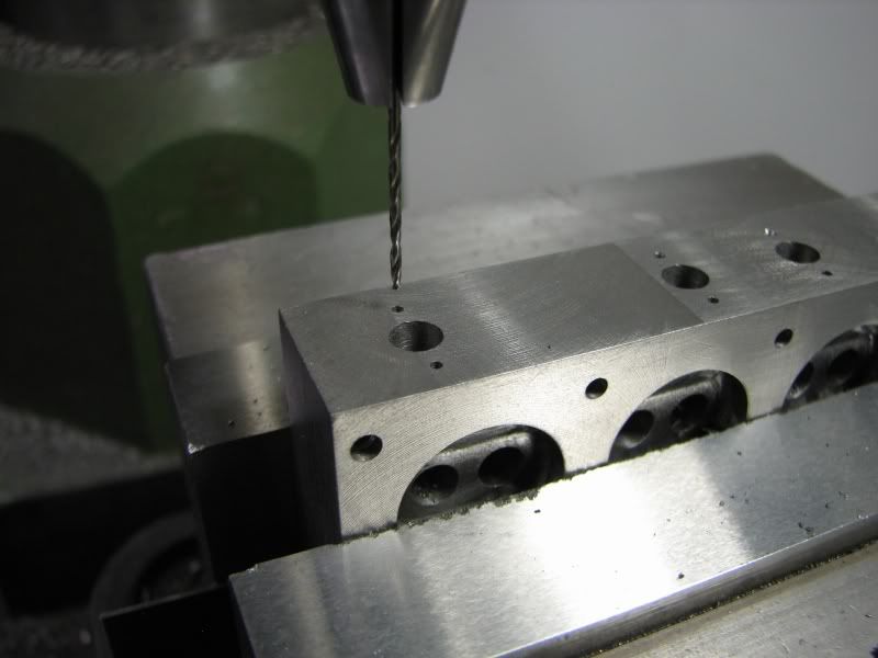
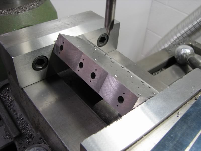
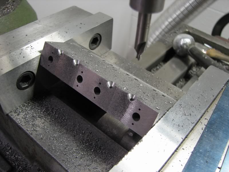
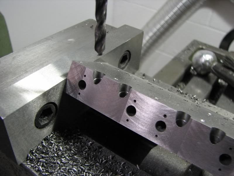
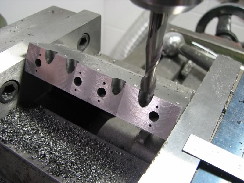
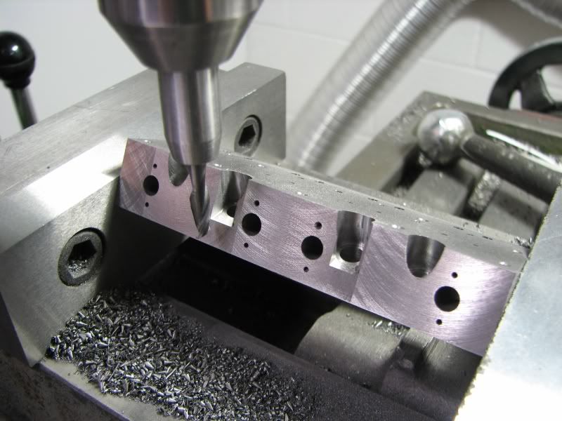
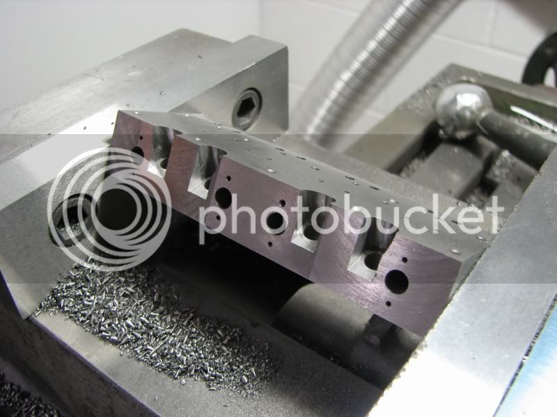
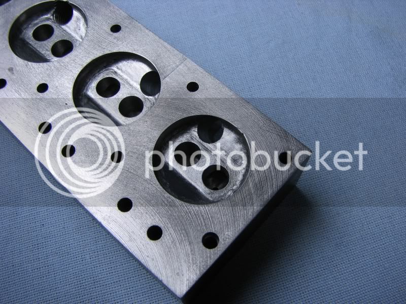
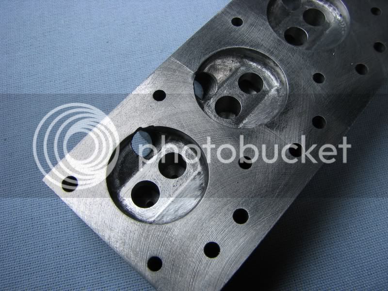
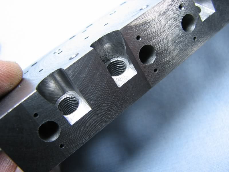
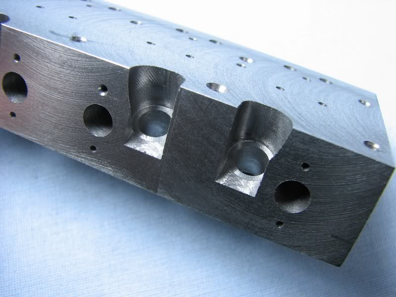
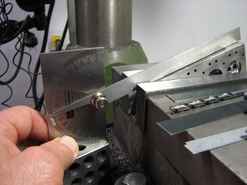
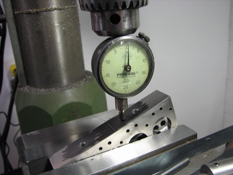
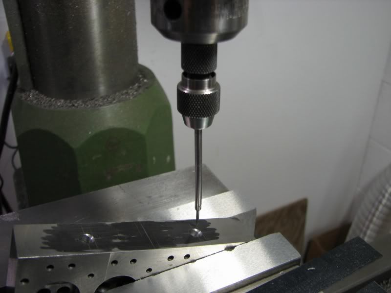
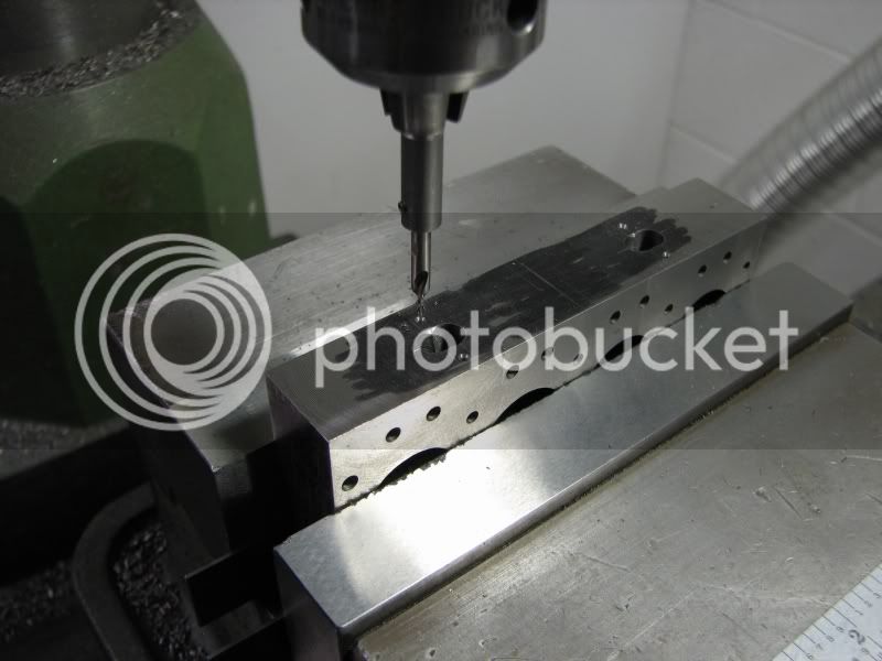
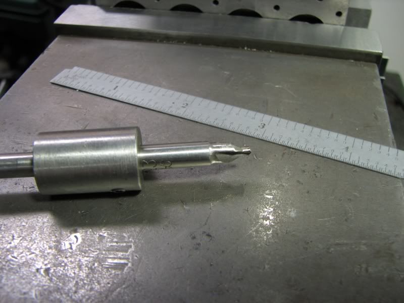
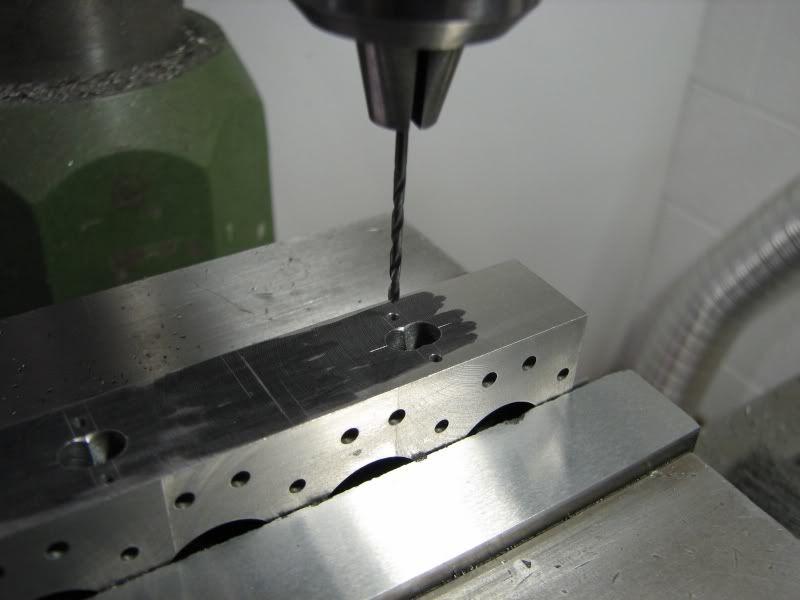
At the time I built my 4 cylinder engine there weren't any commercial spark plugs available. The supply of plugs built in the 60's had just about dried up and they weren't the right length for my engine anyway. The solution, build your own, which I have been doing for years. With the new supply of spark plugs manufactured by Rim Fire I wanted to try them out in my engine but the problem is that when I made my engine I tapped the head for 1/4-28 threads and the new plugs are 1/4-32. My engine runs well enough with my Teflon plugs but with the high rpm it starts to erode the Teflon at the tip. There is no way to make the 32 thread plugs fit in my 28 thread holes so I decided to make a new head. My original head is cast iron, Durabar to be more exact. It is an extremely fine grained iron which cuts very nice and holds nice sharp corners. I like it for the fact that I don't need to make valve guide/seat inserts for the head, everything is just machined into the head. The first few pictures show the piece of iron and my steps in machining it. I always face the widest face first. This gives me a larger surface to locate my edge cuts to. After cutting this face I rotate the block 90 degrees in the vise and cut the narrow edges. You can see in the one picture I use a piece of heavy copper wire as a backup to put even pressure on the irregular surface. My final step is to use pinch down clamps to hold the piece tight against the parallels for the finishing cut.
IMG_7824.jpg

IMG_7827.jpg

IMG_7827.jpg

IMG_7833.jpg

IMG_7838.jpg


Next up came the center drilling and drilling for the various holes, head bolts, push rods, rocker posts etc. There was no specific order, I could have done the combustion chamber side first but chose the top. With the round column mill/drill I set up for the longest tool so that I don't have to move the head any more than I have to.
IMG_7841.jpg

IMG_7844.jpg

IMG_7847.jpg

IMG_7850.jpg
 
I then flipped the block over to start on the port openings and combustion chambers. After touching off my block to get my centers I first center drilled the locations for the ports. The finished hole is .213 diameter so I went in with a .203 diameter drill to rough it out. The finished hole would be done after the combustion chambers were machined so that if I got any little chips on the corners I would have material to clean up. After drilling with the .213 drill I redrilled with a small center drill in the bottom of the pocket for my valve guide hole. The valve guide is .062 diameter so I drilled it undersize and then reamed the guide holes.
IMG_7856.jpg

IMG_7859.jpg
 
The next operations were to rough out the combustion chambers. I calculated how far down I would have to go with a .625 end mill and plunged out each chamber. After this I got a .750 diameter end mill that had the corners worn down and ground a .062 radius on them. The bore is .750 diameter so this would give me a witness for my finishing steps. The combustion chamber is a pent roof shape with 25 degree slopes on the sides. I then layed out the combustion chamber in AutoCad to see what sized cutter I could get into the chamber to rough out the remaining stock. I used a .250 diameter cutter with a .062 radius on the corners. The depth was .143 at the center. I worked down to this depth then walked back and forth until I just came up to the .750 diameter witness.
IMG_7862.jpg

IMG_7865.jpg

IMG_7868.jpg

IMG_7871.jpg


In the pictures you can see how nicely this iron cuts. At this point the port openings have a nice sharp edge but I still have a little stock to come off. No sense taking a chance after all this work. Now I calculated the ramp for my 25 degree roof angle and decided on .025 over and .012 up. All of the radii in the combustion chamber are .062 so to finish up I used a .125 ball mill. As I made my steps I watched the corners with a Mag Lite and worked my way out to the witness diameter. These little cusps will be hand ground and polished when all the machining is finished.
IMG_7877.jpg

IMG_7895.jpg
 
Now it was time to finish up the port bores. I had the head set close to the job so that I would get a minimum of deflection while using the .125 ball mill so it had to be moved back up for the final drilling. I have made many hundreds of parts on this old mill and it has served me well, I just hate having to repickup my work all the time when changing tools. At least the digital readout helps. The final two pictures show the picking up of the part and the final drilling. Actually the closeup shot in the last posting was after the final drilling. I just used it to show the completed combustion chamber machining.
IMG_7883.jpg

IMG_7884.jpg
 
This is a little addendum to this first part of the build. To show that we're all fallible I am including a couple of pictures of my oops. You can see how many steps were involved in machining out the combustion chambers. Everything went splendidly until I was done. I took my last cut and as I cranked the table away in Y I forgot to lift the cutter that last little bit, result, a little ding. I could probably live with it but what if someone takes my engine apart 50 years from now and says "what a shoemaker" I might roll over in my grave ;D
Anyway, I drilled the offending divot out and I will put a little iron pin in it. I'll show the results down the road. I'm off for a couple of days of dirt biking so I won't get back to machining till next week.
gbritnell
IMG_7889.jpg

IMG_7892.jpg
 
George
Thank You,
I feel like I'm getting a leason on how to do my Whittle V8. No ream on the Valve guide holes.? Next installment? Or no? Not necessary?
Tony
 
Hi Tony, you must have missed it. It's about halfway up in the set.
gbritnell
 
Sorry G
I must have dozed off in class :hDe: Rof} scratch.gif
Tony
 
Today we will start back on the build. The next step which I didn't document was turning up a piece of iron to fit in the pin hole. That being done I tapped it in place, about .0025 press fit. The next three pictures show the combustion chambers benched out. I used a combination of small mounted stones in my Dremel flex shaft holder and some round riffler files to clean up the fillets. The black that you see in the combustion chamber is marker ink. I blackened the whole chamber first and this shows you where the high spots are for grinding and finishing.
AZ.jpg

BA.jpg

BB.jpg
 
Up next was a quick step to put the exhaust ports in. Just a matter of centering the part up with my edge finder and then moving to the proper spot and center drilling and drilling. (.213 dia.) I drilled down till the bit broke out into the port and then went a little farther until I could feel the drill touch the far side of the port.
BC.jpg

BD.jpg
 
Excellent thread... I forget how small this engine is, until I see photos like the one with the giant edge-finder in it. :bow:
 
This next step leaves no room for error so after setting up the angle with an indicator and reestablishing my centers I started to put the spark plug ports in. The design of the head has the spark plug port tucked down along the inside edge of the combustion chamber so the angular and location dimensions need to be right on. The first step was to center drill for the hole. You can see that the starting point fell .012 off of the corner of the head so I pecked with the center drill making sure that it stayed true to the center. The next step was to plunge with a .187 ball mill and open up the hole for the 1/4-32 tap drill. I only went far enough to get a good true hole so that the drill wouldn't wander. I then spotfaced with a .312 diameter endmill down to the plug seat.
The final step in this set was to open up the clearance groove with an endmill. This is a preliminary step as more layout and machining will be necessary in this area.
BE.jpg

BF.jpg

BG.jpg

BH.jpg

BI.jpg

BJ.jpg

BK.jpg


Here are several shots of the head after removal from the mill. The spark plug ports were tapped. You can see how accurate the setup has to be by the location of the port in the combustion chamber.
BL.jpg

BM.jpg

BN.jpg

BO.jpg
 
I spoke earlier about using a dial indicator to set up my angles. The next couple of pictures explain what I did. I first set the part close with my protractor. In this case it was a little over 12 degrees. I just snug up the vise to that I can tap the part with my copper hammer to get a fine adjustment on the angle. I then pick a dimension in the X direction that will give me enough room to move the indicator, in this case it was .50. In that distance I find the length of the side opposite (tangent function). Once I have moved the .50 I quill down until my indicator reads -0- and check my digital readout number.
BT.jpg

BU.jpg
 
George,

Awesome post! Keep going I'm taking notes as fast as I can!
;D
Dave
 
The next operation is to put the intake ports in. The ports are siamesed and are close enough that they require some extra steps to insure that they pass between the head bolt holes and wind up in the center of the previously drilled port. With the part on an angle I couldn't just pick up an edge so the part required a little bit of old fashioned layout. Here you can see me 'wiggling' the center lines. These ports are also .213 diameter so I used a .25 center drill taking care that I didn't go all the way down to the body of the drill. The first two ports went easily but the second two which overlap the first holes needed an extra step. I took one of my extra .25 dia. center drills and chucked it up in my lathe. I then ground the body down to about .209 diameter. The reason for .209 was my figuring that if it ran out a little bit I wouldn't be oversize with my starter hole. That done I reset the part to the required angle, center drilled, and drilled until it broke into the port.
BV.jpg

BW.jpg

BY.jpg


The final operation of this series was to center drill and drill for the 2-56 manifold mounting holes.
BX.jpg


That looks great, I love the siamease ports.
I probably would have broken a drill or two.
-B-
 
Tomorrow's operations will be to finish up the shape around the exhaust flanges, open up the spark plug pad area and radius most of the corners in that area. A little bit of added information. I have 14 hours up to this point.
gbritnell
 

Latest posts

Back
Top