4 Cylinder OHV Engine new cylinder head. A work in progress

Home Model Engine Machinist Forum

Help Support Home Model Engine Machinist Forum:

This site may earn a commission from merchant affiliate links, including eBay, Amazon, and others.
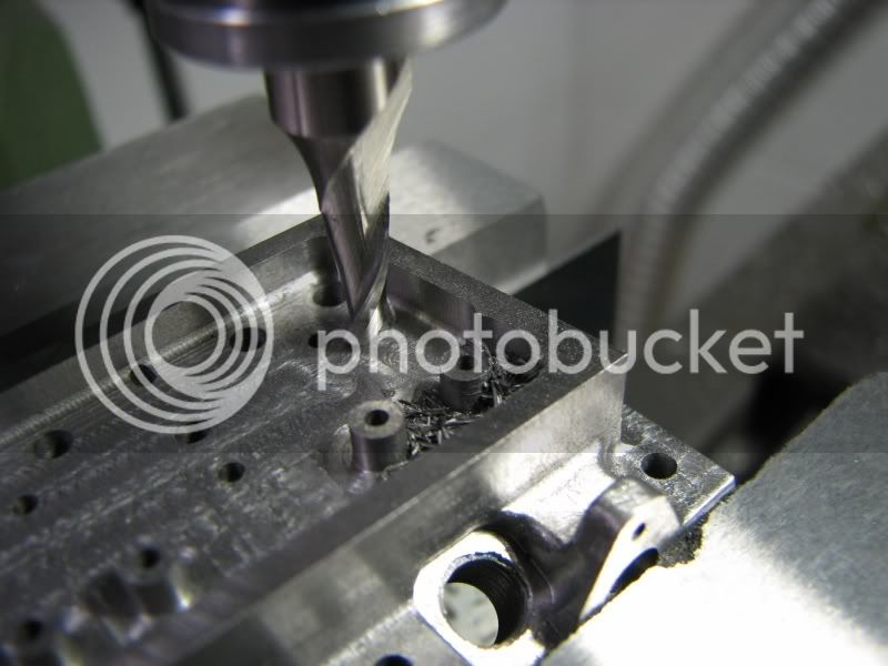
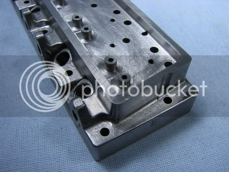
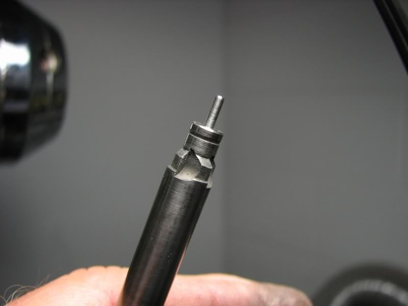
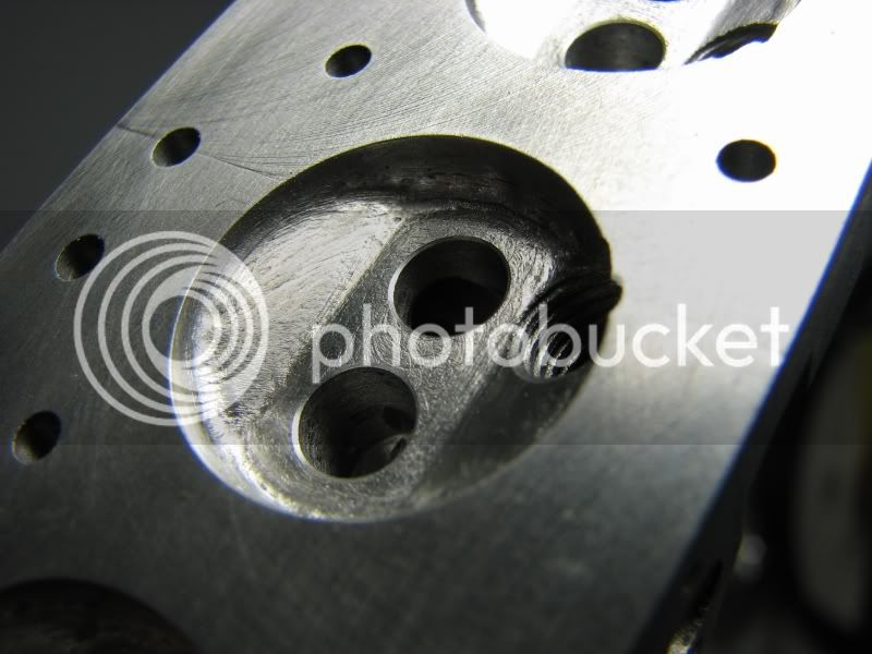
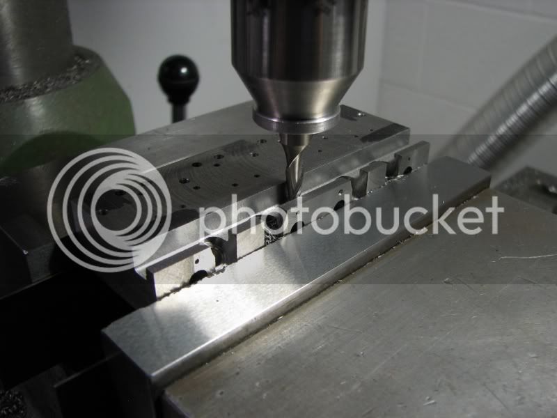
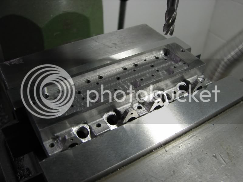
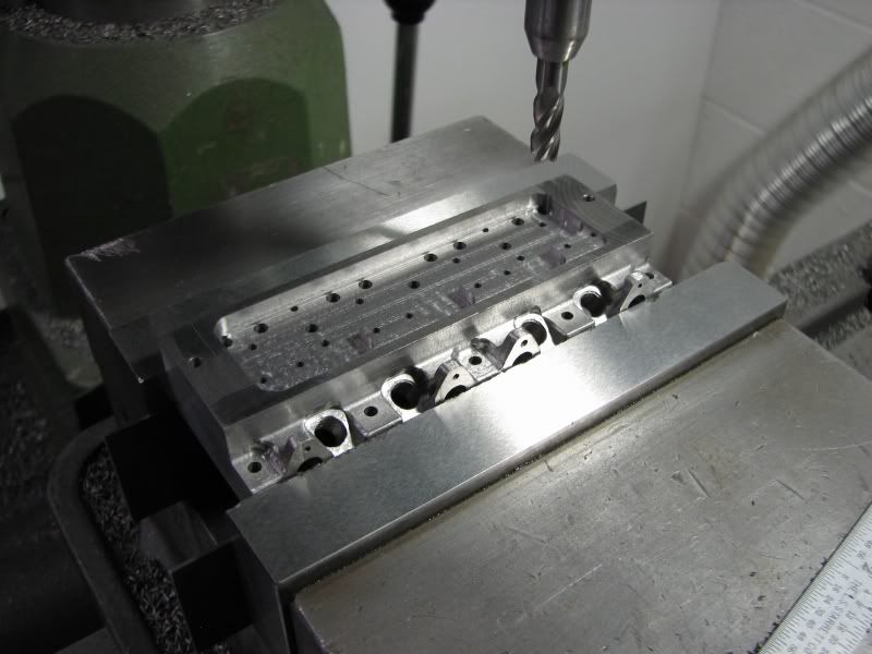
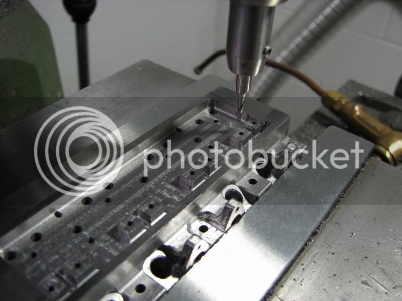
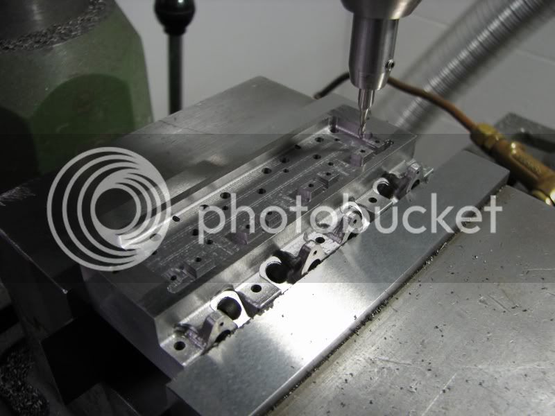
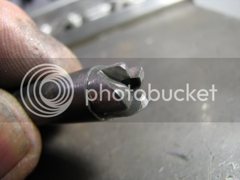
Krown Kustoms, that is why I ground up the center drill for the port operation. Having the first port in I had to go deep enough to get a good starter hole for the second. It was also close enough to size that the drill picked it up and ran true.
gbritnell
 
The exhaust port side of the head now needs finishing up. I first started by removing the excess stock from behind the flanges and cutting the head bolt pads to depth. I then removed the head from the mill and mounted my old header pipes to the face so that I could layout the flange shape on the head. With that accomplished it was back into the mill to step around the flange shapes and finish up my blend cuts. After this the head was set back up on the spark plug angle so that I could clean up the seat area and enlarge it a little. The original design was for my homemade spark plugs which have a longer shank on them and the .312 counterbore was adequate for clearance. This new head will be using the commercial plugs and they need more clearance for the hex.
BZ.jpg

CA.jpg

CB.jpg

CE.jpg


The rocker arm cavity is next up. The head was set up and indicated once again. I went back to my Cad drawing to get some end point dimensions for my .187 end mill. The ends of the rocker cavity are at 6.08 degrees so I needed a tangent point to stop at. I first made a .025 deep cut which is the top of the valve guide bosses and then went down to the full depth of .150 for the remainder of the cavity. I used a .094 dia. mill to run along the front edge. I had .124 space but didn't want to use a .125 endmill and have it cut too wide. I took out as much stock as possible for the next operation.
CF.jpg

CG.jpg

CH.jpg

CI.jpg


Wonderful work!! :bow: :bow: :bow: I can only dream!

Ron
 
With the rocker cavity milled out it was time to cut the valve guide bosses. I made up a spotfacing tool that had the center drilled out to the O.D. of the bosses. The outside edge has a small radius to match the fillet around the inside edge of the cavity. I didn't want to tear down my vise so cutting the flutes required some hand filing. The tool is made from drill rod (silver steel) so the filing was a little harder. I filed the clearances on right up to the edge of my flutes. After hardening the tool I would use an abrasive disc to clean up the faces and thus sharpen the edges. I reset my spindle speed to around 640 rpm and slowly quilled down to the deck of the rocker cavity.
CM.jpg

CJ.jpg

CK.jpg

CL.jpg


GREAT step-by-step pictures (again). Keep it up !!! +1 Karma :)

Mike
 
I might add at this point that anyone who has purchased a set of drawings for this engine and they get to the point of building the head I will lend out the counterboring tool I made. It's not that complicated but unless you want to make your own I have one available.
With the bosses finished it was time to machine the end angles on the rocker chamber. I set my vise over on the required angle and used the same indicating procedure that I used previously. I started out with the .187 dia. endmill and got as close to the valve guide boss as possible and then went in with a .094 endmill to finish up the inside wall. Now it was just a matter of setting over the vise to the other angle and finishing it up.
CN.jpg

CO.jpg

CP.jpg

CQ.jpg
 
Only two machining steps to go. The outer head bolt holes needed a clearance counterbore down the side of the wall so that my socket wrench would fit and finish tapping the remaining holes. I still need to make up a valve seat tool but that won't take long. With the machining complete some hand work was in order. All the outer corners needed to be radiused. The lower corners got a quick hit on the sanding belt and then some hand filing. The corners on the rocker chamber had to be done by hand. The outer two weren't too bad as I could get my files on them without interference but the inner two (exhaust side) were a combination of using a small burr and filing. While filing I had to leave stock at the bottom to match the fillet along the outside wall. This was then cleaned up with a small round file. Some final sanding and polishing and we have one 4 cylinder head. Total time around 21 hours with only two miscues. The first being the little nick in the combustion chamber that needed to be pinned. If you look at the pictures you'll notice it came out quite well. The other was when I was using the .094 dia. endmill in the rocker chamber. I was cleaning up along the front wall (exhaust side) and when I got to the end I misread my readout and started to move backward (Y) and nicked the top of the end valve guide boss. Luckily I was only down .018 so once the valves are assembled it will be hidden. This one wouldn't be as easy to fix as the first. Anyway, I hope you enjoyed the show and possibly learned a thing or two. I have a show to attend in a couple of weeks so I'm not going to take it apart until after that.
gbritnell
CR.jpg

CS.jpg

CT.jpg


Absolutly Beautiful Geroge :bow: :bow: :bow:
Oh ment to let you know I picked up some Tap Magic. I used it tonight on the Whittle. Looks like the stuff works great thanks
Tony
 
George, there is so much good info here for us builders! Thank you for taking the time to pass it on.
Much appreciated.

Dean
 
Beautiful Work George.

Thanks for taking the time to document and share your work with us.

Dave
 
George,

I agree...Thank you ffor sharing Thm:

Regards

Philly
 
I didn't think I had anymore to post to this thread but this morning I made up the valve seat cutting tool and being that some members had trouble with their valves seating I thought I would post it. Normally I make my cutter up with a drilled and reamed hole in the center into which I can insert a piece of stock the diameter of the valve guide. The ports and guides on this engine are so small that I made the tool up in one piece. I turned the pilot to go into the valve guide hole (.062) and the next diameter is the port size (.213). I made an undercut where the 45 degree angle starts so that I would have a good sharp seat. I then put it in my dividing head and cut 4 flutes on it, making sure to go below the .213 diameter. I then filed a small amount of clearance behind the 45 degree cutting edge bringing it right up to the edge of the flutes (with a magnifier). The next step was to harden it, drill rod, carrot orange, dunk straight into water and then polish the diameters. Now using it by hand I insert the tool into the port and and valve guide hole and turn it ever so gently, watching my progress. What you see in the picture is about a .010 seat. When I disassemble the other head I will spot the valves just to make sure that they hit all around on the seats.
CU.jpg

CV.jpg


George,
I was looking to make the very same thing. Then I thought of a reverse countersink

http://www.yardstore.com/browse.cfm/4,5318.html

The only problem is they only come in 100 and 82. Can cut pilot to suit. Thinking about using the 100 till your post. Still thinking the commercial tool will last forever

Tony
 
Tony, it's just that with these small engines valve seating is quite critical and the more accurately you can put the seat in the less trouble you'll have with sealing. A countersink is unsupported so I'd have reservations about using it. The tool you see in the picture took about 20 minutes to make. When you cut your seats if they aren't concentric it will take much more time than that to go back and make the part over.
gbritnell
 
Very true George, the biggest problem with my H/M was grinding valves to get a good seat. I was figuring that a commercial tool would be ground more accurate and using the pilot thru the valve guide would keep me nice and concentric. Is that all the seat you use?
Tony
 
Tony, yes that's all the seat I use. I find that the bigger I make it the harder it is to seal. Going by automotive and motorcycle practice the seat area is about .05-.06. If you have a three angle valve job you have 30 degrees above and 60 degrees below the 45. With a smaller seat you have less chance of something (carbon) sitting on the seat and holding the valve open. These are just things that I have found over the years. Others may have different thoughts on the matter.
gbritnell
 
Thanks George for the inside info. I will rememder that for my Whittle V8
Tony
 

Latest posts

Back
Top