3 Cyl Spider

Home Model Engine Machinist Forum

Help Support Home Model Engine Machinist Forum:

This site may earn a commission from merchant affiliate links, including eBay, Amazon, and others.

Captain Jerry

Project of the Month Winner!!!
Project of the Month Winner
Joined
Dec 2, 2008
Messages
971
Reaction score
8
Hi Y'all

I've been quiet for a while but here I go again. First I got a new lathe (used HF 9x20) so I spent some time cleaning, adjusting, tweaking, and generally fooling around with it. Then I got a new mill (HF Micro Seig X1) and spent some time doing the same with it. Then just as I was getting ready to resume the thread that I started months ago with my 3 cylinder swash plate engine, gremlins attacked my computer. Very frustrating.

It would seem to be working and then would lock-up, shutdown, or both. Sometimes it would restart but often not. After losing a lot of work during these episodes I gave up anything but lurking or an occasional 1 line post. It seems that my youngest son who was visiting last week has exorcised the demons and all appears to be well.

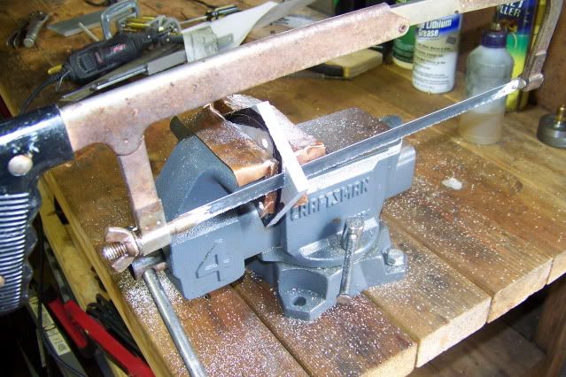
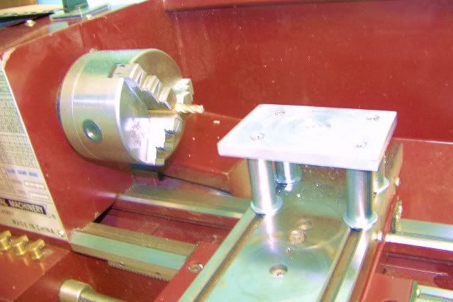
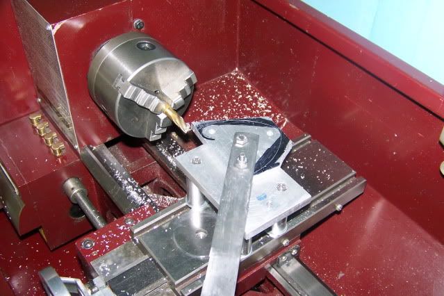
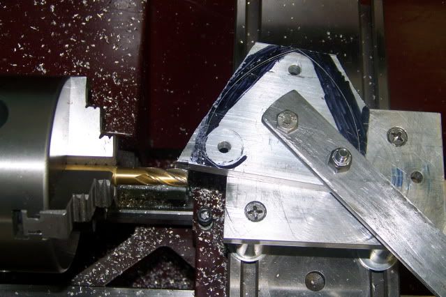
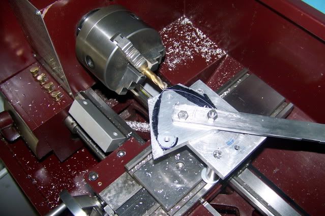
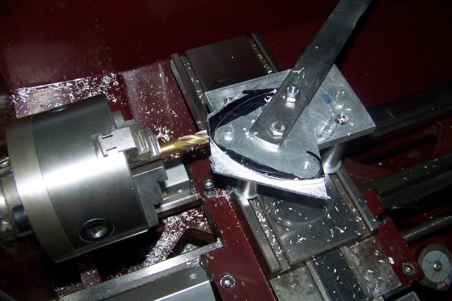
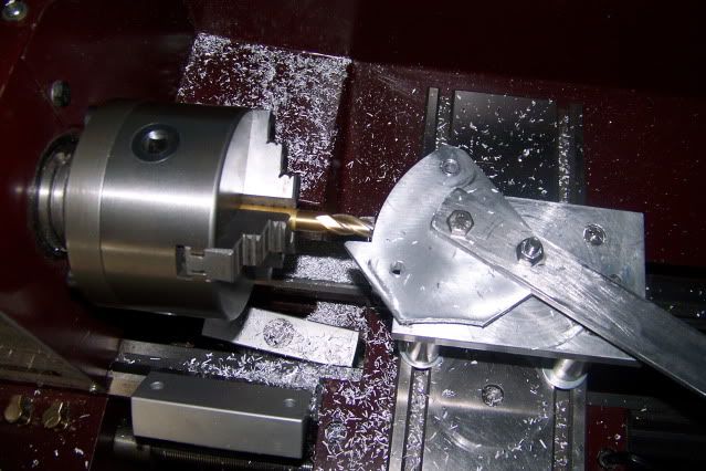
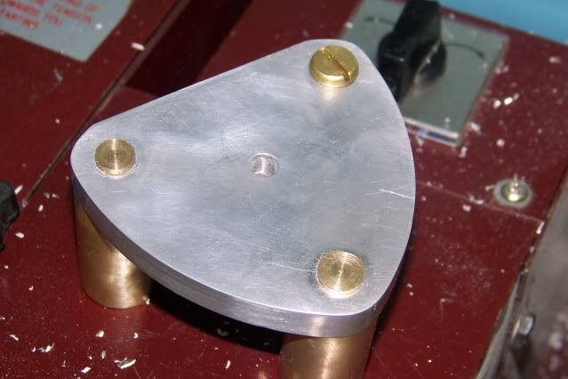
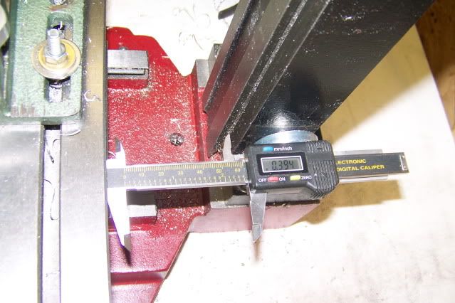
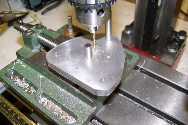
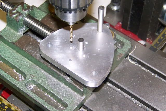
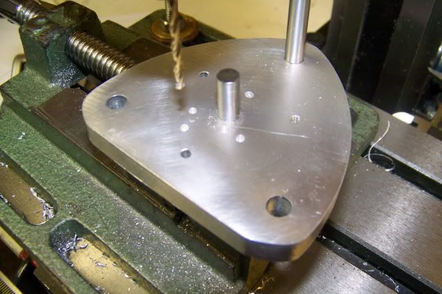
During the silent time, I continued to work on the swash plate engine and my camera was working just fine so I got pictures. I can also afford to spend some time with Alibre' without fear of losing my work so plans are in the works. New equipment offered the opportunity to make some design changes and so I have started this new thread. The new design is quite far along but I will attempt to write the entries in the order of build.

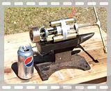
Here is the Swash Plate Engine as I left it and the new version as it is now.


Three Cylinder Spider 038.JPG


Three Cylinder Spider 007.JPG
 
That's great news Jerry. Glad to see you've been at it. Looking forward to more posts and pics.
 
Welcome back Captain. Glad you got rid of those gremlins and look forward to hearing about what you've been up to during the time away.

Bill
 
The revisions on this version begin with the head plate. On the previous version, the triangloid head plate which was cut from 3" wide extruded plate did not reach the outer edge of the cylinders or, to say it another way, the cylinders mounting bolt pattern seemed to be too big. I wanted to be able to blend the outer curve of the plate into the radius of the cylinders but I could not reduce the cylinder spacing (reasons later) and I was going to use 3" plate if I could. The reason for the curving edge is to provide for the six standoff bars which connect the two end plates and which need to be spaced wide enough to clear the spider plate.

The answer came as I slept. Do away with the second plate and I won't need standoffs. The edges can be straight and I can make it fit within the 3" width. But two of the standoffs do double duty as control rods to limit the rotation of the spider. OK, find another way to mount the control rods and I got it made. But I like the appearance of the curving sides. OK, make one side straight, put it on the bottom and I can just make it fit on 3" plate. It will be a little wider than 3" but that can be layed out on the length of the plate.

Hear I am with my old faithfull Armstrong Power Hacksaw cutting the plate.

ArmstrongPowerHacksaw.jpg


At this point, I did not have rotary table or even a mill so I had to come up with an alternate method of cutting the curved edges. I had seen post on this forum that showed manually rotating a part around a fixed pivot to get a curved end so starting with this thought, I built a milling, drilling table for the lathe cross slide. The idea was to mount an endmill in the lathe and rotate the plate around a pin through the cylinder mounting holes.

Here is the table mounted on the cross slide. The table top is aluminum 3/8" x 3" x 6". The legs are 3/4" dia steel tube, cut with the hacksaw and faced to length on the lathe. The table height was set for 5/16" below the lathe spindle center (allowing for fender washers at each end of the tube to prevent marking the cross slide or gouging the table). 1/4" Carriage bolts in the T slots on the slide, topped with a coupling nut and 1/4" - 20 machine screws through the plate into the top of the coupling nut makes a reasonable rigid setup.

RotaryTableonLathe.jpg


My shop is in an aluminum shed but the shed is under a shade tree which may account for some of my technique.

The pivot point is a 1/4"-20 hex head bolt up through the table, through a cylinder mounting hole in the plate, through a hole in the control arm and secured with a nylock nut on top. The control arm is a 12" length of steel bar with two holes that match the distance from plate center to cylinder center. A short 1/4" bolt is placed through the other hole in the bar and into the center of the plate. I now have a good grip on the plate with plenty of leverage for control.

Having neither a collet or an end mill holder, I was forced to grip the end mill in the 3-jaw chuck. Hard jaws, hard shank = poor grip and scarred surfaces so I slipped the end mill shank into a short piece of thin brass tubing (K&S Hobby tubing). The tubing made a nice close fit and the wall thickness is thin enough that it was not necessary to slit the tubing to allow it to collapse under chuck pressure. A side benefit to this is that when I take the cutter out of the chuck, I can slide it all the way into the tube which then acts as a guard for the cutter in the drawer.

I am using a 3/8" dia end mill and with the table set to 5/16" below center, I will be taking a 1/4" cut off of the top surface of the plate. The bottom of the cutter is rotating toward the rear of the lathe so the plate must be rotated from back to front to be feeding into the rotation, conventional milling. The depth of cut is controlled by moving the lathe carriage toward the headstock. Positioning the cross slide properly is important. Ideally, the center of the pivot should line up with the rear edge of the cutter. This allows the edge of the cutter to do all of the work. If the pivot is too far back the milled edge will be slightly convex. If the pivot is too far forward, most of the cutting action will be on the end of the cutter and you can feel the vibration in your eye teeth. Whe correctly set and with the spindle speed at about 600 RPM, the cut is surprisingly smooth and the effort to feed the plate is surprisingly light.

Here is what it looked like:

Millingtheplate1.jpg


Millingtheplate2.jpg


Millingtheplate3.jpg


Millingtheplate4.jpg


Millingtheplate5.jpg


TheMilledPlate.jpg


My next post will include the plans for the plate including x/y positioning for all holes to be drilled in the face.

Jerry


I guess I should add that since the width of the cut is only 1/4" and the plate is 3/8" then it is necessary to flip the plate over to remove the remaining material. When in this position, the material to be removed is nearly centered on the cutter. It could be cut by rotating the material from back to front as before. However, the cutting action tends to lift the plate from the table and some chatter occurs. The cutting action when rotating the plate into the cutter from front to back tends to hold the plate down on the table and the chatter is eliminated. When cutting in this direction, move the carriage to the front so that the pivot center is in line with the front edge of the cutter.

If you have a mill and a rotary table, you won't have to resort to this method, but the table will still come in very hand when drilling the air passages in the edge of the plate.

The final picture shows the plate radius blended into the cylinder radius. This was done by eye with a file and the disc sander.

Jerry
 
If you tried to download the section view above and failed, try it again. I think I fixed it.

Jerry
 
So I went and bought a mill. HF Micro Mill X1. I realize that its not much of a mill by some standards but I think it will be fine for my needs. Armed with my 20% off coupon,I went to the Jacksonville HF store where I had seen one on display but there was no stock. The item is special order only but if I pre-paid and had it shipped to the store, there would be no freight charge and they would happily honor the coupon discount. As I was laying down my credit card, the store managersaid "Would you want to take the demo model if I discounted it?". Total cost, out the door, $200 with full warranty. All that was missing was the manual which I printed off of their web site.

Disasembled, cleaned up, honed the gibs, stoned some burrs on the ways, reassembled, lots of adjusting and I am well satisfied. As long as I stick with reasonably sized engines it should do just fine. I made some quick and dirty mounts for a couple of digital calipers and started making chips.

The Spider Engine head plate has three cylinder ports, 1 inlet and 1 exhaust port, and three bolt holes for mounting the valve cover plate. The drawings show the x/y positions of these holes, relative to the center shaft location. The bolt holes are drilled clear thru and all port holes are drill 3/16" deep to intersect their respective passages in the plate. I think it best to drill the holes in the face first and the intercepted passages afterward.

Here are pics of the setup and the drilling. The fixed vice jaw was indicated parallel with the Y axis and the top surface of the jaws was skimmed flat. Two 1/4" pins were fitted through the plate in the shaft and Cylinder #1 positions. With these two pins gripped in the vise, the plat is positioned for the operation.

ThreeCylinderSpider053.jpg


ThreeCylinderSpider054.jpg


ThreeCylinderSpider055.jpg


ThreeCylinderSpider056.jpg


This could also be accomplished with adequate accuracy using a drill press and carefull mark out.

More to follow.
 
I was reading this post from the start and just thinking, what a work he is doing without a mill! :D

but you have done the right choice Cap Jerry: a mill is almost indispensable in the shop. glad to see that you have got yours. and at a very good price!

nice thread on the engine too!!!
 
A lathe is indispensable, a mill is very nice to have. I built the prototype of this engine on a well used Unimat sl1000 which is not really either but it showed me the possibilities. It also affected the kinds of projects that I could attempt. One of the things that I learned from the Unimat is that really sharp tools can make up for a lack of rigidity. Really sharp tools let you take very light cuts. I learned how to sharpen HSS and developed a feel for the depth and feed on aluminum, mild steel, and even stainless. I don't think I will ever be able to sharpen an endmill.
I was able to make a flycutter that used 1/8" HSS bits and swung a 1"dia cut on the unimat with very good results but any attempt to use an endmill greater that 1/8" dia was useless.

One of the first real production projects that I attempted was to reproduce the end plate with the large radius arc. But still lacking a rotary table I had to use the manual feed method that I used on the lathe. The result was the same but it took more time on the mill.

The mill has already changed some of the design on this version because it makes some things possible that previously required a design work around. I'll try to mention these changes as I proceed.

Jerry

 
What do you call a work-in-progress when there is very little progress? Well, that's what this is.

It is hard to anticipate all of the little things that stand in the way of shop time. That may be topic for a new thread if someone wants to have a go at it.

This week, I am babysitting my daughter's 5 dogs while she and her husband take a short trip to Pittsburgh but I did bring my computer with me. The dogs aren't much for conversation so the active brain fills in. I can't make real chips so virtual chips will have to do. The engine pictured in the attachment is a six cylinder engine assembled from standard non-modified parts for the spider engine in this thread. It can be assembled in two ways just by re-orienting the eccentrics and the spiders. In the configuration shown, with the parts in phase, it produces 6 power strokes per revolution behaving much like a three cylinder double acting engine.

If the eccentric and spider on one end are set 180 degrees out of phase from the other, it produces 3 power strokes per rotation, with opposing pistons acting at the same time, doubling the effective piston area and the power on each stroke. The really cool thing about this configuration is that it is perfectly balanced with every motion offset by an equal but opposite motion of it sister at the other end.

I got through 70 years without realizing how much I suffered from A.D.D. I think it's this model engineering thing. Every day I learn so much and have new discoveries (well, new to me) that I keep running of in all directions. Maybe for Christmas I'll get one of those new phones with the built in GPS. A GPS doesn't really tell you where you are going but at least you can look back and see where you've been. Enough crap. Take a look.

Jerry

View attachment Double Triple Axial Spider - Alibre Design.pdf
 
Captain Jerry said:
What do you call a work-in-progress when there is very little progress?

Well I still call it a work-in-progress. :)
6 cylinders? Are you building that?
 
Yes Zeep, I am building it. I am actually building enough parts to build 3 of the 3 cylinder version. There are no additional parts required to build the 6 cylinder version and since the parts are identical, I guess I am building one of each, a Triple and a Double Triple. I will build it. I will not become distracted. I will concentrate.

Oh! Look! A butterfly!
 
A slight modification after sleeping on it. Since the head plates will be assembled back to back, the inlet ports will be on opposite sides as will the exhaust ports. I'll have to make one of them left-handed. Makes no real difference on the single version but a lot more convenient on the double.

Jerry
 
You wouldn't believe how cold it is in FLORIDA! I finally got a little time for shop work this morning and the water pot by my bench grinder was frozen solid. You guys in the frozen north might think I'm a wimp but there is no heat in my shop so I turned around and went back to the house and sat on the couch and made CAD engines and drank hot coffee. Here is the results.

This is the where I am heading with the spider engine which I guess I will call the "Double Triple". In the first sixty seconds of the clip, the two halves of the engine are in phase and the engine produces six power strokes per revolution. The cylinders and the valve cover are transparent so you can see the pistons and the rotary slide valve.

At about the 60 second mark, the engine changes configuration and the two halves are 180 degrees out of phase. Now it produces three double power strokes per revolution as the opposed pistons act at the same time. The Clip ends at about 1min 26 secs but a black screen runs for another minute or so. Not sure why.

It's going to warm up next week but till then, Im sticking to the couch and reading.

Jerry

[ame]http://www.youtube.com/watch?v=fFVMdsgHEOI[/ame]
 
Very nice animation. Do you export the video directly from your CAD software?
 
Deferr

Glad you liked it. I am using Alibre 11 which does not export motion sequences ($99 Version). With the number of parts in motion, the frame update of Alibre is very slow so I used a screen capture program (Camtasia free trial) and then increased the frame rate by 800% in the editing process so the motion is smooth and continuous.

Camtasia is very powerful but it's $300 so I only have 29 more days to play with it. If anyone knows of a good freeware capture and editor, please post it.

Jerry
 
Update

The six cylinder version "Double Triple" is running. I got it to run a few weeks ago but when I started to fine tune it for testing, I found some problems that made me stop and rethink a few things and then redesign a few of the major components. These redesigns need to be tested so don't expect a lot of polish in the following. Plenty of spit ... no polish.

Problem 1. The two rotary slide valves were fixed to the common shaft with set screws (grub screws), facing in opposite direction, could not be reliable adjusted so performance was erratic.

Fix: Replace the set screws with pins through the shaft and put a slot in the eccentrics so that they can float on the shaft. This will let the valves be adjusted independently and reliably. The eccentrics need to be thicker to accommodate the slot. New eccentrics, new slide rings, new valve body.

Problem 2. Piston wear. The pistons in the original version were a compromise and I knew they would be a problem but I didn't have an better design at the time. The piston rods in this type of engine cannot use a normal wrist pin because it must be free to rotate in all directions. What it really needs is a ball joint and I could not come up with a reliable design within my ability to produce so I went with a compromise. By reducing the piston thickness to a thin disk and putting a radius on the edge, in effect making the piston like a slice out of the center of a sphere, the rod could be fixed solidly to the piston. Unlike a wrist pin the rod must move all directions but less than 2 degrees in any direction so the piston can rock in the bore and still maintain a seal in the cylinder without binding. It does work but the contact between the piston and the cylinder is a thin line. High wear and subsequent loss of compression and loss of power.

Fix: Find a way to make a reliable joint within the .625 bore. Make a real piston height of 1/2 inch with oil grooves and the option to add rings or o-ring seal in the future. Do it six times! I did. I'll post the design and the build of these pistons in the next day or two but I wanted to get this video posted. It may help me stay focused.

Jerry


Latest posts

Back
Top