1/6th Scale Easton & Anderson Beam Engine

Home Model Engine Machinist Forum

Help Support Home Model Engine Machinist Forum:

This site may earn a commission from merchant affiliate links, including eBay, Amazon, and others.

Jasonb

Project of the Month Winner!!!
Project of the Month Winner
Joined
Mar 30, 2008
Messages
3,786
Reaction score
1,267
Location
Surrey, UK
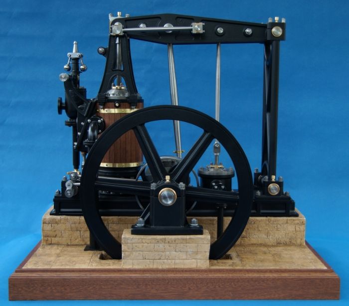
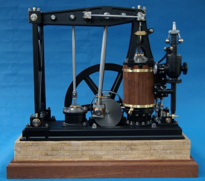
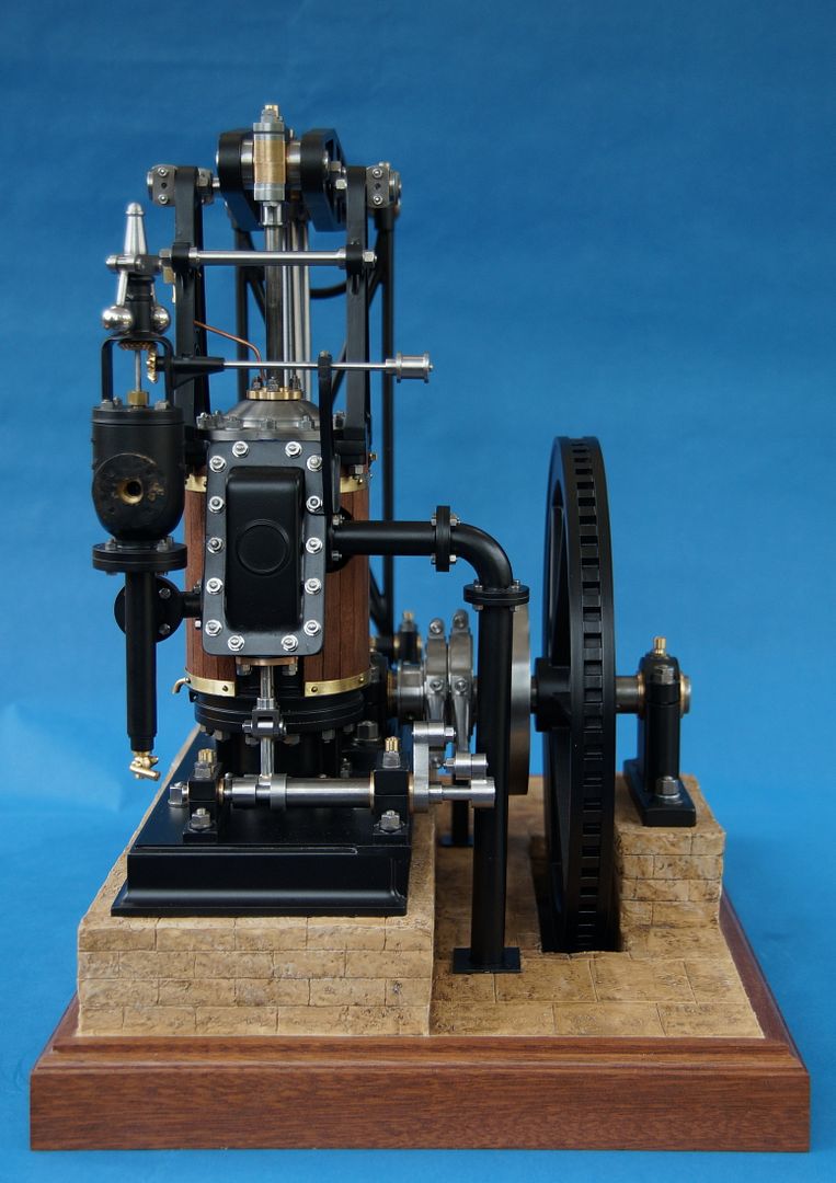
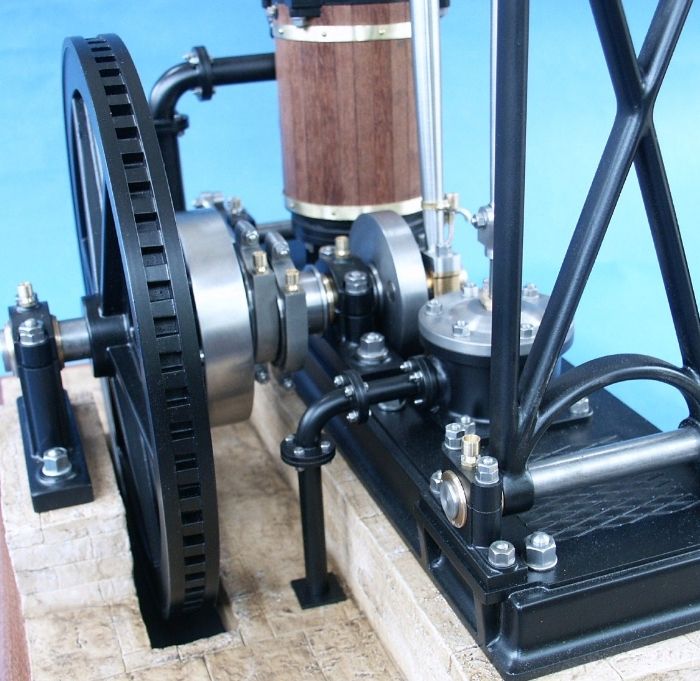
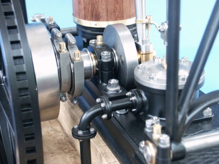
Well I remembered how it all went back together so this is it just about done and dusted, there is still a belt for the governor and a makers plate to do. Full details of the build are here

DSC00508_zps35dc0494.jpg


DSC00510_zps924d9144.jpg


DSC00511_zpsd19c7402.jpg


DSC00523_zps2199f911.jpg


DSC00512_zps19b17048.jpg


DSC00513_zpsa2de1819.jpg


DSC00516_zps5913ee47.jpg


DSC00517_zps9bec0b9e.jpg


DSC00519_zpsd6793d85.jpg


DSC00524_zpsd3d5e25b.jpg


PICT0396_zps2e55e336.jpg


PICT0397_zps2fe22213.jpg


PICT0408_zps95ed0fc6.jpg


PICT0409_zps647696be.jpg


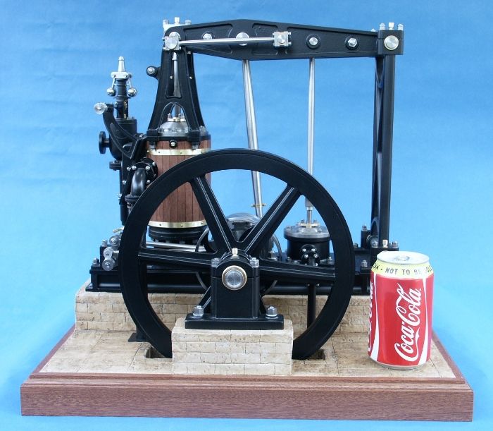
And the usual Coke can shot so you can get an idea of size

PICT0419_zps740cacbb.jpg


And finally a short video, the compressor was having a job to keep up thats why it starts off a bit fast for my liking and then dies out.

[ame]http://youtu.be/jDhF7zYsK1o[/ame]

J
 
Jason,
Bravo! Excellent work! Very neat and crisp, almost Cherry Hill'ish.
 
I usually don't get in for the painted look but man that is beautiful!!! I followed the other thread shortly as my time as a member isn't very long. Very impressed with your work! It shows you enjoy this stuff!
 
Amazing work Jason, just beautiful mate! Also, the bricks are just a brilliant finish to the project.

cheers, Ian
 
What a super piece of work.

I have watched the fabrication jobs in particular with great interest.

I don't remember seeing a photo of the valves, but I assume there is an expansion valve with a fixed cut-off. If you are always going to run it at appropriately low speed, with no load, I think the valve setting could be tweaked to give more even running, though I suppose it still may need to bed in.

BTW, you mentioned early on that the air pump is for pumping air round the condenser. It think this is unlikely. Normally the purpose of an air pump is to remove condensate from the condenser, along with any air that has leaked in.
 
What air pump ? Surely this is an engine used for pumping water, like so many of this type - there is no power take off that I can see for driving other machinery, so if the pump on the base is to do with a condenser then I don't see what the engine's purpose is.

I was curious to see the barring ring on the flywheel, as I thought that these engines always stop with the piston at BDC due to the weight of the beam. I doubt they can stop in any position like a beam engine, though again I suppose it depends if the driven load is capable of stopping it.
 
As I said in my opening description (see link in first post) most people think of beam engines as large engines used for pumping water. However this is a small beam engine (5ft flywheel) that could be used to drive machines in a factory or mill.

If you also look closely at the engine you will see that inboard of the flywheel is a large pully which was via overhead shafting used to drive the gas exhausters that pulled the gas from the retorts and pumped it into the gas holders at Winchester gas works where it was originally used. I have based my model on when it entered preservation in 1936 which is when the photos and descriptions of it in Watkins books are based.

E&A Description.jpg


E&A Description 2.jpg
 
Last edited:
Interesting, my mistake and apologies, I have seen boiler feed pump and water pump located there, but never an air pump. Is the condenser all located in a pit below the air pump (which presumably would also pump out the condensed water) ? Maybe that could explain the checkerplate access. I wonder what should be down there.
 
Probably something we will never know as whatever was under there never made it out of the gasworks:(

There are a couple of similar engines in museums by the company when they went under the name Eaton & Amos and these do have the smaller water feed pumps.

http://www.geograph.org.uk/photo/2201061
 
With the history your fine model is surely worthy of being in a museum. Regarding the condenser, it is tricky if the bits have gone missing - K Harris has a chapter on modelling condensers and air pumps in his book "Model stationary and marine steam engines" - his air pump drawing on p101 could easily be what you have the top of in your model.

My grandfather modelled a grasshopper pumping engine I think in the 1930s, it was in a pumphouse on the broads. Nothing like the quality of model you have produced, but he put a fair bit of detail into the pump (he was a hospital engineer, so steam and pumps were everyday to him). Curiously he modelled it with a plain 2-part beam, but same beam support as the one you have modelled. I also have a vintage model of a grasshopper engine in wood and brass, but this has the one-piece beam and a ladder type beam support. I would love to find out more about the make of this one, but have found very little original literature on different makers and this one doesn't look like Easton&Amos types. I was interested to see the comment that the later type grasshoppers had the two part beam, so this may indicate this is an earlier design. I fancy using it as a prototype for a working model at some point, and your build log certainly provides a lot of inspiration.
http://i924.photobucket.com/albums/ad84/oldnoccer/SmallScale/grasshopper_zps7f520d03.jpg
http://i924.photobucket.com/albums/ad84/oldnoccer/SmallScale/Overall_zpsc28f2fc5.jpg
 

Latest posts

Back
Top